EP0249823B1 - Vorrichtung zur Steuerung eines Herzschrittmachers mittels Impedanzmessung an Körpergeweben - Google Patents
Vorrichtung zur Steuerung eines Herzschrittmachers mittels Impedanzmessung an Körpergeweben Download PDFInfo
- Publication number
- EP0249823B1 EP0249823B1 EP87108116A EP87108116A EP0249823B1 EP 0249823 B1 EP0249823 B1 EP 0249823B1 EP 87108116 A EP87108116 A EP 87108116A EP 87108116 A EP87108116 A EP 87108116A EP 0249823 B1 EP0249823 B1 EP 0249823B1
- Authority
- EP
- European Patent Office
- Prior art keywords
- frequency
- signal
- low
- impedance
- stimulation
- Prior art date
- Legal status (The legal status is an assumption and is not a legal conclusion. Google has not performed a legal analysis and makes no representation as to the accuracy of the status listed.)
- Expired - Lifetime
Links
- 238000002847 impedance measurement Methods 0.000 title description 8
- 102100026827 Protein associated with UVRAG as autophagy enhancer Human genes 0.000 title 1
- 101710102978 Protein associated with UVRAG as autophagy enhancer Proteins 0.000 title 1
- 230000000638 stimulation Effects 0.000 claims description 22
- 238000011156 evaluation Methods 0.000 claims description 5
- 230000003247 decreasing effect Effects 0.000 claims description 2
- 238000001914 filtration Methods 0.000 claims 1
- 230000029058 respiratory gaseous exchange Effects 0.000 description 5
- 239000008280 blood Substances 0.000 description 4
- 210000004369 blood Anatomy 0.000 description 4
- 238000005259 measurement Methods 0.000 description 4
- 230000004060 metabolic process Effects 0.000 description 4
- 239000000463 material Substances 0.000 description 3
- 230000001419 dependent effect Effects 0.000 description 2
- 230000036387 respiratory rate Effects 0.000 description 2
- 230000002503 metabolic effect Effects 0.000 description 1
- 230000000737 periodic effect Effects 0.000 description 1
Images
Classifications
-
- A—HUMAN NECESSITIES
- A61—MEDICAL OR VETERINARY SCIENCE; HYGIENE
- A61B—DIAGNOSIS; SURGERY; IDENTIFICATION
- A61B5/00—Measuring for diagnostic purposes; Identification of persons
- A61B5/05—Detecting, measuring or recording for diagnosis by means of electric currents or magnetic fields; Measuring using microwaves or radio waves
- A61B5/053—Measuring electrical impedance or conductance of a portion of the body
- A61B5/0535—Impedance plethysmography
-
- A—HUMAN NECESSITIES
- A61—MEDICAL OR VETERINARY SCIENCE; HYGIENE
- A61N—ELECTROTHERAPY; MAGNETOTHERAPY; RADIATION THERAPY; ULTRASOUND THERAPY
- A61N1/00—Electrotherapy; Circuits therefor
- A61N1/18—Applying electric currents by contact electrodes
- A61N1/32—Applying electric currents by contact electrodes alternating or intermittent currents
- A61N1/36—Applying electric currents by contact electrodes alternating or intermittent currents for stimulation
- A61N1/362—Heart stimulators
- A61N1/365—Heart stimulators controlled by a physiological parameter, e.g. heart potential
- A61N1/36514—Heart stimulators controlled by a physiological parameter, e.g. heart potential controlled by a physiological quantity other than heart potential, e.g. blood pressure
- A61N1/36521—Heart stimulators controlled by a physiological parameter, e.g. heart potential controlled by a physiological quantity other than heart potential, e.g. blood pressure the parameter being derived from measurement of an electrical impedance
Definitions
- the invention relates to a device for impedance measurement on body tissues according to the preamble of patent claim 1.
- Impedance measurements in body tissue have so far been used to determine mechanical volume changes in the body, e.g. the stroke volume of the heart as well as breathing due to chest movements.
- the change in impedance can be used to control the frequency of pacemakers.
- a device for impedance measurement in a frequency-controlled pacemaker is known from US Pat. No. 4,303,075. There, however, only the higher-frequency signal components as a measure of breathing or the stroke volume of the heart are filtered out of the detected impedance signal and the stimulation frequency is thus controlled.
- the measurement of periodic fluctuations in impedance thus detects the changes of 1 or F on the line section.
- the object of the present invention is to develop a device for impedance measurement of the type mentioned at the outset in the sense of a metabolism-dependent pacemaker control.
- the invention is based on the knowledge that the conductance ⁇ R of the above-mentioned relationship contains metabolic components which give a direct measure of the metabolism (thus a direct reference to stress). It also assumes. that there are higher-frequency signal components in the detected impedance signal, which essentially reflect changes in 1 or F, and that there is also a low-frequency component, which is a direct measure of the conductance ⁇ R (in contrast to the subject of US Pat. No. 3,532,086, which shows low-frequency components as blood volume). Conventional devices for impedance measurement in pacemaker technology, such as, for example, that of US Pat. No.
- the cut-off frequency of the low-pass filter can be varied as a function of the stimulation frequency, in the sense that it is shifted to higher values with increasing stimulation frequency and to lower values with decreasing stimulation frequency.
- a temperature influence compensation device is additionally provided, with the aid of which the measured conductance is cleaned of temperature influences.
- the impedance meter 1 of FIG. 1 comprises an AC voltage generator 2 (e.g. 1 kHz AC voltage generator) as a signal source for impressing an electrical signal, which, via electrode lines 3 and 4 with associated electrodes 5 and 6, a (not shown) body tissue a constant AC voltage V ⁇ (e.g. 1 kHz alternating voltage).
- the measuring arrangement of FIG. 1 is preferably designed for intracorporeal measurement. So at least the electrodes 5 and 6 are implanted in the body tissue. Depending on the impressed AC voltage V ⁇ , the voltage drop caused by the current in the electrode lines 3 and 4 is detected by means of a voltmeter 8 via a low-resistance series resistor 7 (for example 100 ohms).
- the output signal of the voltmeter 8 is then fed to a low-pass filter 9, the upper limit frequency of which is in the range 0.1 to 0.4 Hz (can preferably be varied in this frequency range, as will be explained in more detail later with reference to FIG. 3).
- the low-pass filter 9 separates from the output signal S I (impedance signal) of the voltmeter 8 only the low-frequency signal components S NF , which correspond to the conductance ⁇ R in the body tissue.
- the separated low-frequency signal components S NF can be taken from the signal output 10 of the low-pass filter 9.
- the impedance meter 11 comprises an alternating current source 12 (for example 1 kHZ alternating current source), which the Body tissue through the electrode lines 3 and 4 and the associated electrodes 5 and 6 impresses a constant alternating current I ⁇ (eg 1 kHz alternating current).
- the entire measuring system is again preferably designed as an intracorporeal measuring system.
- the AC voltage between the electrodes 5 and 6 is measured by means of a voltmeter 13 connected in parallel, which includes a divider to form 1 / V ⁇ .
- the output signal S I (impedance signal) of the voltmeter 13 is then evaluated in a low-pass filter 9 in the same way as previously described in connection with FIG.
- FIG. 3 shows the use of a measuring arrangement according to FIG. 1 or FIG. 2 in a frequency-controlled pacemaker 14.
- the electrode 5 is also the stimulation electrode of the pacemaker 14, while the electrode 6 is formed by the conductive (e.g. metallic) housing of the pacemaker.
- the electrode line 3 corresponds to the stimulation catheter of the pacemaker.
- the frequency-controlled pacemaker 14 comprises a pulse generator 15 for the stimulation pulses 16.
- the repetition rate of the stimulation pulses 16 (stimulation frequency) can be controlled on the pulse generator 15 via a frequency control part 17 as a function of the filtered low-frequency signal component S NF at the output 10 of the low-pass filter 9.
- the control takes place in the sense that when the conductance ⁇ R changes, the stimulation frequency is changed proportionally.
- the stimulation frequency therefore increases when the filtered low-frequency signal component S NF (and thus also the conductance ⁇ R ) increases.
- the pacing rate is in Conversely, less if the signal components S NF (and thus the conductance ⁇ R ) decrease.
- the cut-off frequency of the low-pass filter 9 can be controlled via a control line 19 as a function of the output signal of the frequency control part 17 in the sense that it increases in the range 0.1 to 0.4 Hz with increasing stimulation frequency and with falling stimulation frequency is shifted to lower values accordingly.
- the frequency control part 17 is not controlled directly by the signal S NF , but rather with the interposition of a correction element 20 for compensating for temperature influences.
- the conductance ⁇ R increases with increasing temperature.
- the correction element 20 corrects the signal S NF for the conductance in the reverse manner.
- the stimulation catheter 3 itself can also consist of a material that compensates for the temperature response of the conductivity (eg NTC resistance material) or a resistor made of such material can be built into the stimulation catheter 3.
- a material that compensates for the temperature response of the conductivity eg NTC resistance material
- a resistor made of such material can be built into the stimulation catheter 3.
- the frequency control part 17 also comprises a subtraction stage 22, which subtracts a programmable fixed value (for example between 80 to 90% of the mean value of the low-frequency signal) from the temperature-compensated low-frequency signal S NF . This eliminates an unspecific signal component (offset) for the control.
- a programmable fixed value for example between 80 to 90% of the mean value of the low-frequency signal
Landscapes
- Health & Medical Sciences (AREA)
- Life Sciences & Earth Sciences (AREA)
- Heart & Thoracic Surgery (AREA)
- Cardiology (AREA)
- Engineering & Computer Science (AREA)
- Animal Behavior & Ethology (AREA)
- Biophysics (AREA)
- Veterinary Medicine (AREA)
- Radiology & Medical Imaging (AREA)
- Biomedical Technology (AREA)
- Hematology (AREA)
- Public Health (AREA)
- Nuclear Medicine, Radiotherapy & Molecular Imaging (AREA)
- General Health & Medical Sciences (AREA)
- Pathology (AREA)
- Molecular Biology (AREA)
- Medical Informatics (AREA)
- Surgery (AREA)
- Physics & Mathematics (AREA)
- Physiology (AREA)
- Electrotherapy Devices (AREA)
- Measurement And Recording Of Electrical Phenomena And Electrical Characteristics Of The Living Body (AREA)
- Measurement Of The Respiration, Hearing Ability, Form, And Blood Characteristics Of Living Organisms (AREA)
Description
- Die Erfindung bezieht sich auf eine Vorrichtung zur Impedanzmessung an Körpergeweben gemäß Oberbegriff des Patentanspruchs 1.
- Eine solche Vorrichtung mit einer Auswerteeinrichtung im Sinne der Heraustrennung sowohl von niederfrequenten als auch höherfrequenten signalanteilen ist im Zusammenhang mit der Bestimmung von Blutverlusten bei einer Operation durch die US-PS 3 532 086 vorbekannt. Der niederfrequente Anteil ist ein Maß für das Blutvolumen.
- Impedanzmessungen im Körpergewebe (einschließlich Blut) dienten bisher zur Bestimmung von mechanischen Volumenänderungen des Körpers, z.B. des Schlagvolumens des Herzens sowie auch der Atmung aufgrund Thoraxbewegungen. Die Änderung der Impedanz kann zur Frequenssteuerung von Herzschrittmachern verwendet werden. So ist aus der US-PS 4 303 075 eine Vorrichtung zur Impedanzmessung bei einem frequenzgesteuerten Herzschrittmacher bekannt. Dort werden jedoch lediglich die höherfrequenten Signalanteile als Maß für die Atmung oder das Schlagvolumen des Herzens aus dem erfaßten Impedanzsignal herausgefiltert und damit die Stimulationsfrequenz gesteuert.
- Grundlage der Impedanzmessung ist vereinfacht die folgende physikalische Beziehung:

wobei R die Impedanz,
σR der Leitwert
1 der wirksame Elektrodenabstand (cm) und
F der wirksame Leitungsquerschnitt (cm²)
zwischen den Elektroden ist. - Die Messung periodischer Impedanzschwankungen erfaßt also die Änderungen von 1 oder F auf der Leitungsstrecke.
- Eine unmittelbare Aussage über den Stoffwechsel, der ein direktes Maß für die Körperbelastung wäre, ist nicht möglich.
- Aufgabe der vorliegenden Erfindung ist es, eine Vorrichtung zur Impedanzmessung der eingangs genannten Art im Sinne einer stoffwechselabhängigen Herzschrittmachersteuerung weiterzubilden.
- Die Aufgabe wird erfindungsgemäß durch die kennzeichnenden Merkmale des Patentanspruchs 1 gelöst.
- Die Erfindung geht aus von der Erkenntnis, daß im Leitwert σR der obengenannten Beziehung metabolische Anteile stecken, die ein direktes Maß für den Stoffwechsel (damit direkter Bezug zur Belastung) abgeben. Sie geht ferner davon aus. daß im erfaßten Impedanzsignal höherfrequente Signalanteile stecken, die im wesentlichen Änderungen von 1 oder F wiederspiegeln, und daß auch ein niederfrequenter Anteil vorhanden ist, der ein direktes Maß für den Leitwert σR ist (im Gegensatz zum Gegenstand der US-PS 3 532 086, der niederfrequente Anteile als Blutvolumen anzeigt). Konventionelle Vorrichtungen zur Impedanzmessung in der Herzschrittmachertechnik, wie z.B. jene der US-PS 4 303 075, filtern die höherfrequenten Signalanteile als Maß für die Atmung oder das Schlagvolumen des Herzens aus dem erfaßten Impedanzsignal heraus und steuern damit z.B. die Frequenz eines Herzschrittmachers. Bei vorliegender Erfindung werden jedoch anstelle der höherfrequenten die niederfrequenten Signalanteile des Impedanzsignals abgetrennt und zur Frequenzsteuerung eines Herzschrittmachers herangezogen. Man erhält dadurch ein direkt vom Leitwert abhängiges Signal, das eine unmittelbare Aussage über den Stoffwechsel und damit die momentane Belastung, z.B. eines Patienten, zuläßt und somit ein erheblich genaueres Steuerungssignal für die Stimulationsfrequenz als der bekannte höherfrequente Anteil des Impedanzsignals bildet.
- In einer vorteilhaften Ausgestaltung der Erfindung ist die Grenzfrequenz des Tiefpaßfilters in Abhängigkeit von der Stimulationsfrequenz variierbar, in dem Sinne, daß sie mit steigender Stimulationsfrequenz zu höheren Werten und mit sinkender Stimulationsfrequenz entsprechend zu niedrigeren Werten verschoben wird. Dadurch ergibt sich der Vorteil, daß die Grenzfrequenz des Filters in Abhängigkeit von der Atemfrequenz, die sich analog zur Belastung (und damit auch zur sich ändernden Stimulationsfrequenz) verändert, immer möglichst hoch ist, aber dennoch gleichzeitig immer unterhalb der Atemfrequenz liegt. Dadurch kann es nicht zu störendem Einfluß der Atmung auf das Meßergebnis kommen.
- In einer weiteren vorteilhaften Ausgestaltung der Erfindung ist zusätzlich noch eine Temperatureinfluß-Kompensationseinrichtung vorgesehen, mit deren Hilfe der gemessene Leitwert von Temperatureinflüssen bereinigt wird.
- Weitere Vorteile und Einzelheiten der Erfindung ergeben sich aus der nachfolgenden Beschreibung eines Ausführungsbeispiels anhand der Zeichnung und in Verbindung mit den Unteransprüchen.
- Es zeigen:
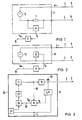
- Figur 1
- eine erste und
- Figur 2
- eine zweite Ausführungsform für die Impedanzmessung als Teile eines in
- Figur 3
- gezeigten Ausführungsbeispiels der erfindungsgemäßen Vorrichtung in Form eines freqenzgesteuerten Herzschrittmachers.
- Der Impedanzmesser 1 der Figur 1 umfaßt als Signalquelle zum Einprägen eines elektrischen Signals einen Wechselspannungserzeuger 2 (z.B. 1 kHz-Wechselspannungserzeuger), der über Elektrodenleitungen 3 und 4 mit zugehörigen Elektroden 5 und 6 einem (nicht dargestellten) Körpergewebe eine konstante Wechselspannung V∼ (z.B. 1 kHz-Wechsel-spannung) einprägt. Die Meßanordnung der Figur 1 ist dabei vorzugsweise zur intrakorporalen Messung ausgelegt. Es sind also zumindest die Elektroden 5 und 6 im Körpergewebe implantiert. In Abhängigkeit von der eingeprägten Wechselspannung V∼ wird über einen niederohmigen Serienwiderstand 7 (z.B. 100 Ohm) der vom Strom in den Elektrodenleitungen 3 und 4 verursachte spannungsabfall mittels eines Spannungsmessers 8 erfaßt. Das Ausgangssignal des Spannungsmessers 8 wird dann einem Tiefpaßfilter 9 zugeführt, dessen obere Grenzfrequenz im Bereich 0,1 bis 0,4 Hz liegt (vorzugsweise in diesem Frequenzbereich variierbar ist, wie später anhand der Figur 3 noch näher erläutert wird). Das Tiefpaßfilter 9 trennt aus dem Ausgangssignal SI (Impedanzsignal) des Spannungsmessers 8 lediglich die niederfrequenten Signalanteile SNF, die dem Leitwert σR im Körpergewebe entsprechen, heraus. Die herausgetrennten niederfrequenten Signalanteile SNF können vom Signalausgang 10 des Tiefpaßfilters 9 abgenommen werden.
- In der Figur 2 umfaßt der Impedanzmesser 11 eine Wechselstromquelle 12 (z.B. 1 kHZ-Wechselstromquelle), die dem Körpergewebe über die Elektrodenleitungen 3 und 4 sowie den zugehörigen Elektroden 5 und 6 einen konstanten Wechselstrom I ∿ (z.B. 1 kHz-Wechselstrom) einprägt. Das gesamte Meßsystem ist wieder vorzugsweise als intrakorporales Meßsystem ausgelegt. Gemessen wird diesmal die Wechselspannung zwischen den Elektroden 5 und 6 mittels eines parallelgeschalteten Spannungsmessers 13, der einen Dividierer zur Bildung von 1/V ∿ beinhaltet. Das Ausgangssignal SI (Impedanzsignal) des Spannungsmessers 13 wird dann in derselben Weise, wie zuvor im Zusammenhang mit der Figur 1 beschrieben, in einem Tiefpaßfilter 9 ausgewertet.
- Die Figur 3 zeigt die Anwendung einer Meßanordnung gemäß der Figur 1 oder Figur 2 in einem frequenzgesteuerten Herzschrittmacher 14. Gleiche Bauelemente sind dabei mit gleichen Bezugsziffern versehen. Die Elektrode 5 ist im vorliegenden Fall gleichzeitig die Stimulationselektrode des Herzschrittmachers 14, während die Elektrode 6 durch das leitende (z.B. metallische) Gehäuse des Herzschrittmachers gebildet ist. Die Elektrodenleitung 3 entspricht dem Stimulationskatheter des Herzschrittmachers.
- Der frequenzgesteuerte Herzschrittmacher 14 umfaßt einen Pulsgenerator 15 für die Stimulationsimpulse 16. Die Folgefrequenz der Stimulationsimpulse 16 (Stimulationsfrequenz) ist am Pulsgenerator 15 über ein Frequenzsteuerteil 17 in Abhängigkeit von dem herausgefilterten niederfrequenten Signalanteil SNF am Ausgang 10 des Tiefpaßfilters 9 steuerbar. Die Steuerung erfolgt in dem Sinne, daß bei sich änderndem Leitwert σR die Stimulationsfrequenz proportional geändert wird. Die Stimulationsfrequenz steigt also, wenn der herausgefilterte niederfrequente Signalanteil SNF (und damit auch der Leitwert σR) zunimmt. Die Stimulationsfrequenz wird in umgekehrter Weise geringer, wenn die Signalanteile SNF (und damit der Leitwert σR ) abnehmen.
- Wie in der Figur 3 angedeutet ist, ist die Grenzfrequenz des Tiefpaßfilters 9 über eine Steuerleitung 19 in Abhängigkeit vom Ausgangssignal des Frequenzsteuerteils 17 steuerbar in dem Sinne, daß sie im Bereich 0,1 bis 0,4 Hz mit steigender Stimulationsfrequenz zu höheren Werten und mit sinkender Stimulationsfrequenz entsprechend zu niedrigeren Werten verschoben wird. Es tritt der bereits eingangs geschilderte Vorteil ein, daß das Meßergebnis trotz erwünscht höchstmöglicher Grenzfrequenz des Tiefpaßfilters 9 von der Atmung unbeeinflußt bleibt.
- Ferner ergibt sich aus der Figur 3, daß die Steuerung des Frequenzsteuerteiles 17 vom Signal SNF nicht unmittelbar, sondern unter Zwischenschaltung eines Korrekturgliedes 20 zur Kompensation von Temperatureinflüssen erfolgt. Der Leitwert σR erhöht sich mit steigender Temperatur. Das Korrekturglied 20 korrigiert das Signal SNF für den Leitwert in umgekehrter Weise. Zum Erfassen der Temperatur dient ein Temperaturfühler 21, der im Gehäuse des Herzschrittmachers oder z.B. außerhalb des Gehäuses angeordnet sein kann. Es versteht sich von selbst, daß auch der Impedanzmesser 1 bzw. 11 sowie das Tiefpaßfilter 9 vorzugsweise im Inneren des Schrittmachergehäuses untergebracht sind.
- Anstelle des Temperaturfühlers 21 und des Korrekturgliedes 20 kann aber auch der Stimulationskatheter 3 selbst aus einem den Temperaturgang der Leitfähigkeit kompensierenden Material (z.B. NTC-Widerstandsmaterial) bestehen oder im Stimulationskatheter 3 kann ein Widerstand aus solchem Material eingebaut sein.
- Das Frequenzsteuerteil 17 umfaßt auch noch eine Subtraktionsstufe 22, die vom temperaturkompensierten niederfrequenten Signal SNF einen programmierbaren festen Wert (z.B. zwischen 80 bis 90 % des Mittelwertes des niederfrequenten Signals) subtrahiert. Dadurch wird ein für die Steuerung unspezifischer Signalanteil (Offset) eliminiert.
Claims (6)
- Vorrichtung zur Impedanzmessung an Körpergeweben mit einer Signalquelle (2,12) zum Einprägen eines elektrischen Signals (V ,I ) in das Körpergewebe, einer Einrichtung (7,8,13) zum Erfassen eines Impedanzsignals (SI) aus dem Körpergewebe in Abhängigkeit vom eingeprägten elektrischen Signal (V ,I ) und einer Auswerteeinrichtung (9) zur Auswertung des Impedanzsignals (SI) im Sinne der Heraustrennung der dem Leitwert (σR) entsprechenden niederfrequenten Signalanteile (SNF), die einen Signalausgang (10) für die herausgetrennten Signalanteile (SNF) umfaßt, dadurch gekennzeichnet, daß vom Signalausgang (10) der Auswerteeinrichtung (9) die niederfrequenten Signalanteile als Steuersignal (SNF) dem Frequenzsteuerteil (17) eines frequenzgesteuerten Herzschrittmachers (16) zugeführt werden zur Steuerung der Stimulationsfrequenz in dem Sinne, daß bei sich änderndem Leitwert (σR) die Stimulationsfrequenz entsprechend geändert wird.
- Vorrichtung nach Anspruch 1, dadurch gekennzeichnet, daß die Auswerteeinrichtung ein Tiefpaßfilter (9) mit einer oberen Grenzfrequenz im Bereich 0,1 bis 0,4 Hz umfaßt.
- Vorrichtung nach Anspruch 1 oder 2, dadurch gekennzeichnet, daß die Grenzfrequenz des Tiefpaßfilters (9) in Abhängigkeit von der Stimulationsfrequenz in dem Sinne variierbar ist, daß sie mit steigender Stimulationsfrequenz zu höheren Werten und mit sinkender Stimulationsfrequenz entsprechend zu niedrigeren Werten verschoben wird.
- Vorrichtung nach einem der vorangehenden Ansprüche, dadurch gekennzeichnet, daß die Auswerteeinrichtung eine Einrichtung (20) zur Kompensation des Temperatureinflusses auf das niederfrequente Signal (SNF) umfaßt.
- Vorrichtung nach Anspruch 4, dadurch gekennzeichnet, daß das Frequenzsteuerteil (17) eine Subtraktionsstufe (22) umfaßt, die vom temperaturkompensierten niederfrequenten Signal (SNF) einen programmierbaren festen Wert subtrahiert.
- Vorrichtung nach Anspruch 5, dadurch gekennzeichnet, daß der feste Wert im Bereich von 80 bis 90% des Mittelwertes des niederfrequenten Signals (SNF) liegt.
Applications Claiming Priority (2)
| Application Number | Priority Date | Filing Date | Title |
|---|---|---|---|
| DE3620280 | 1986-06-16 | ||
| DE3620280 | 1986-06-16 |
Publications (2)
| Publication Number | Publication Date |
|---|---|
| EP0249823A1 EP0249823A1 (de) | 1987-12-23 |
| EP0249823B1 true EP0249823B1 (de) | 1991-12-18 |
Family
ID=6303142
Family Applications (1)
| Application Number | Title | Priority Date | Filing Date |
|---|---|---|---|
| EP87108116A Expired - Lifetime EP0249823B1 (de) | 1986-06-16 | 1987-06-04 | Vorrichtung zur Steuerung eines Herzschrittmachers mittels Impedanzmessung an Körpergeweben |
Country Status (4)
| Country | Link |
|---|---|
| US (1) | US4805621A (de) |
| EP (1) | EP0249823B1 (de) |
| JP (1) | JPH0832262B2 (de) |
| DE (1) | DE3775281D1 (de) |
Cited By (8)
| Publication number | Priority date | Publication date | Assignee | Title |
|---|---|---|---|---|
| US8099250B2 (en) | 2005-08-02 | 2012-01-17 | Impedimed Limited | Impedance parameter values |
| US8487686B2 (en) | 2007-03-30 | 2013-07-16 | Impedimed Limited | Active guarding for reduction of resistive and capacitive signal loading with adjustable control of compensation level |
| US8548580B2 (en) | 2005-07-01 | 2013-10-01 | Impedimed Limited | Monitoring system |
| US8594781B2 (en) | 2007-01-15 | 2013-11-26 | Impedimed Limited | Monitoring system |
| US8744564B2 (en) | 2004-06-18 | 2014-06-03 | Impedimed Limited | Oedema detection |
| US8836345B2 (en) | 2007-11-05 | 2014-09-16 | Impedimed Limited | Impedance determination |
| US9392947B2 (en) | 2008-02-15 | 2016-07-19 | Impedimed Limited | Blood flow assessment of venous insufficiency |
| US9585593B2 (en) | 2009-11-18 | 2017-03-07 | Chung Shing Fan | Signal distribution for patient-electrode measurements |
Families Citing this family (158)
| Publication number | Priority date | Publication date | Assignee | Title |
|---|---|---|---|---|
| DE3732640C1 (de) * | 1987-09-28 | 1989-05-18 | Alt Eckhard | Medizinisches Geraet zum Ermitteln von physiologischen Funktionsparametern |
| FR2624024A1 (fr) * | 1987-12-07 | 1989-06-09 | Brehier Jacques | Stimulateur cardiaque et procede de reglage de ce stimulateur |
| US5003975A (en) * | 1988-04-19 | 1991-04-02 | Siemens-Pacesetter, Inc. | Automatic electrode configuration of an implantable pacemaker |
| AU614118B2 (en) * | 1988-04-19 | 1991-08-22 | Pacesetter Ab | Configuration programming of an implantable pacemaker |
| DE58906649D1 (de) * | 1989-05-22 | 1994-02-17 | Siemens Ag | Implantierbares medizinisches Gerät mit Mitteln zum Stimulieren von Gewebekontraktionen mit einstellbarer Stimulationsintensität und Verfahren zum Betrieb eines solchen Gerätes. |
| US5074303A (en) * | 1990-03-08 | 1991-12-24 | Cardiac Pacemakers, Inc. | Rate adaptive cardiac pacer incorporating switched capacitor filter with cutoff frequency determined by heart rate |
| US5233515A (en) * | 1990-06-08 | 1993-08-03 | Cosman Eric R | Real-time graphic display of heat lesioning parameters in a clinical lesion generator system |
| US5058583A (en) * | 1990-07-13 | 1991-10-22 | Geddes Leslie A | Multiple monopolar system and method of measuring stroke volume of the heart |
| US5063937A (en) * | 1990-09-12 | 1991-11-12 | Wright State University | Multiple frequency bio-impedance measurement system |
| US5280429A (en) * | 1991-04-30 | 1994-01-18 | Xitron Technologies | Method and apparatus for displaying multi-frequency bio-impedance |
| US5309917A (en) * | 1991-09-12 | 1994-05-10 | Drexel University | System and method of impedance cardiography and heartbeat determination |
| JPH0729755B2 (ja) * | 1991-09-20 | 1995-04-05 | 象印チエンブロック株式会社 | 捲上牽引機における遊転制御装置 |
| US5713896A (en) * | 1991-11-01 | 1998-02-03 | Medical Scientific, Inc. | Impedance feedback electrosurgical system |
| EP0566726A1 (de) * | 1991-11-08 | 1993-10-27 | Ep Technologies, Inc. | Systeme und verfahren zur gewebeablation unter überwachung der gewebeimpedanz |
| AU3067292A (en) * | 1991-11-08 | 1993-06-07 | Ep Technologies Inc | Ablation electrode with insulated temperature sensing elements |
| US5282840A (en) * | 1992-03-26 | 1994-02-01 | Medtronic, Inc. | Multiple frequency impedance measurement system |
| US5540681A (en) * | 1992-04-10 | 1996-07-30 | Medtronic Cardiorhythm | Method and system for radiofrequency ablation of tissue |
| US5573533A (en) * | 1992-04-10 | 1996-11-12 | Medtronic Cardiorhythm | Method and system for radiofrequency ablation of cardiac tissue |
| US5197467A (en) * | 1992-06-22 | 1993-03-30 | Telectronics Pacing Systems, Inc. | Multiple parameter rate-responsive cardiac stimulation apparatus |
| IL102300A (en) * | 1992-06-24 | 1996-07-23 | N I Medical Ltd | Non-invasive system for determining of the main cardiorespiratory parameters of the human body |
| US5271413A (en) * | 1992-07-22 | 1993-12-21 | Dalamagas Photios P | Method to sense the tissue for injection from a hypodermic needle |
| US5357956A (en) * | 1992-11-13 | 1994-10-25 | American Cardiac Ablation Co., Inc. | Apparatus and method for monitoring endocardial signal during ablation |
| US5342357A (en) * | 1992-11-13 | 1994-08-30 | American Cardiac Ablation Co., Inc. | Fluid cooled electrosurgical cauterization system |
| US5334193A (en) * | 1992-11-13 | 1994-08-02 | American Cardiac Ablation Co., Inc. | Fluid cooled ablation catheter |
| WO1994010922A1 (en) * | 1992-11-13 | 1994-05-26 | Ep Technologies, Inc. | Cardial ablation systems using temperature monitoring |
| US5335667A (en) * | 1992-11-20 | 1994-08-09 | University Of Utah Research Foundation | Method and apparatus for determining body composition using bioelectrical impedance |
| SE9300283D0 (sv) * | 1993-01-29 | 1993-01-29 | Siemens Elema Ab | Foerfarande och anordning foer elektrodoevervakning vid elektriska hjaertstimulatorer |
| US5335668A (en) * | 1993-04-30 | 1994-08-09 | Medical Scientific, Inc. | Diagnostic impedance measuring system for an insufflation needle |
| US5454377A (en) * | 1993-10-08 | 1995-10-03 | The Ohio State University | Method for measuring the myocardial electrical impedance spectrum |
| US5800470A (en) * | 1994-01-07 | 1998-09-01 | Medtronic, Inc. | Respiratory muscle electromyographic rate responsive pacemaker |
| US5524632A (en) * | 1994-01-07 | 1996-06-11 | Medtronic, Inc. | Method for implanting electromyographic sensing electrodes |
| US5409009A (en) * | 1994-03-18 | 1995-04-25 | Medtronic, Inc. | Methods for measurement of arterial blood flow |
| US5413113A (en) | 1994-03-21 | 1995-05-09 | Milne; Robert D. | Electronic allegro-sensitivity test device |
| US5584830A (en) * | 1994-03-30 | 1996-12-17 | Medtronic Cardiorhythm | Method and system for radiofrequency ablation of cardiac tissue |
| US6560480B1 (en) | 1994-10-24 | 2003-05-06 | Transscan Medical Ltd. | Localization of anomalies in tissue and guidance of invasive tools based on impedance imaging |
| US5810742A (en) * | 1994-10-24 | 1998-09-22 | Transcan Research & Development Co., Ltd. | Tissue characterization based on impedance images and on impedance measurements |
| US6678552B2 (en) * | 1994-10-24 | 2004-01-13 | Transscan Medical Ltd. | Tissue characterization based on impedance images and on impedance measurements |
| US5534018A (en) * | 1994-11-30 | 1996-07-09 | Medtronic, Inc. | Automatic lead recognition for implantable medical device |
| FI106529B (fi) * | 1995-05-26 | 2001-02-28 | Instrumentarium Oy | Menetelmä potilaan hengityksen tarkkailemiseksi |
| US5706823A (en) * | 1995-08-18 | 1998-01-13 | Quinton Instrument Company | Electrophysiology filtering system |
| IT1281370B1 (it) * | 1995-09-29 | 1998-02-18 | Medico S P A | Misura di impedenza transvalvolare adatta all'uso in dispositivi impiantabili. |
| US5741311A (en) * | 1996-06-27 | 1998-04-21 | Medtronic, Inc. | Implantable medical device system with method for determining lead condition |
| RU2108060C1 (ru) * | 1996-10-17 | 1998-04-10 | Йелстаун Корпорейшн Н.В. | Устройство для измерения электрической проводимости кожи |
| US6033399A (en) | 1997-04-09 | 2000-03-07 | Valleylab, Inc. | Electrosurgical generator with adaptive power control |
| US7901400B2 (en) | 1998-10-23 | 2011-03-08 | Covidien Ag | Method and system for controlling output of RF medical generator |
| US20040167508A1 (en) * | 2002-02-11 | 2004-08-26 | Robert Wham | Vessel sealing system |
| US7364577B2 (en) | 2002-02-11 | 2008-04-29 | Sherwood Services Ag | Vessel sealing system |
| US20100042093A9 (en) * | 1998-10-23 | 2010-02-18 | Wham Robert H | System and method for terminating treatment in impedance feedback algorithm |
| US7137980B2 (en) * | 1998-10-23 | 2006-11-21 | Sherwood Services Ag | Method and system for controlling output of RF medical generator |
| DE19943651A1 (de) * | 1999-09-13 | 2001-03-15 | Soehnle Ag Montlingen | Körperfettmesswaage |
| US7283868B2 (en) * | 2000-04-07 | 2007-10-16 | The Johns Hopkins University | Apparatus for sensing human prostate tumor |
| US6564079B1 (en) | 2000-07-27 | 2003-05-13 | Ckm Diagnostics, Inc. | Electrode array and skin attachment system for noninvasive nerve location and imaging device |
| US7302292B2 (en) | 2002-04-04 | 2007-11-27 | Mirabel Medical Ltd. | Breast cancer screening |
| SE0101917D0 (sv) * | 2001-05-31 | 2001-05-31 | St Jude Medical | A blood flow measuring apparatus |
| US7044911B2 (en) * | 2001-06-29 | 2006-05-16 | Philometron, Inc. | Gateway platform for biological monitoring and delivery of therapeutic compounds |
| US7593775B2 (en) * | 2002-01-15 | 2009-09-22 | Therapeutic Innovations | Sports equipment with resonant muscle stimulator for developing muscle strength |
| US7035691B2 (en) * | 2002-01-15 | 2006-04-25 | Therapeutic Innovations, Inc. | Resonant muscle stimulator |
| US6963772B2 (en) | 2002-04-17 | 2005-11-08 | The Board Of Trustees Of The Leland Stanford Junior University | User-retainable temperature and impedance monitoring methods and devices |
| DE60315970T2 (de) | 2002-05-06 | 2008-05-21 | Covidien Ag | Blutdetektor zur kontrolle einer elektrochirurgischen einheit |
| US20040049241A1 (en) * | 2002-09-10 | 2004-03-11 | Therapeutic Innovations, Inc. | Distributed muscle stimulator |
| US7044948B2 (en) * | 2002-12-10 | 2006-05-16 | Sherwood Services Ag | Circuit for controlling arc energy from an electrosurgical generator |
| US7255694B2 (en) * | 2002-12-10 | 2007-08-14 | Sherwood Services Ag | Variable output crest factor electrosurgical generator |
| US20040236385A1 (en) * | 2003-01-31 | 2004-11-25 | Therapeutic Innovations, Inc. | Rectal resonant muscle stimulator |
| EP1617776B1 (de) * | 2003-05-01 | 2015-09-02 | Covidien AG | System zur programmierung und kontrolle eines elektrochirurgischen generatorsystems |
| WO2004098376A2 (en) * | 2003-05-12 | 2004-11-18 | Cheetah Medical Inc. | System, method and apparatus for measuring blood flow and blood volume |
| US20050021020A1 (en) * | 2003-05-15 | 2005-01-27 | Blaha Derek M. | System for activating an electrosurgical instrument |
| CA2542798C (en) | 2003-10-23 | 2015-06-23 | Sherwood Services Ag | Thermocouple measurement circuit |
| ES2372045T3 (es) | 2003-10-23 | 2012-01-13 | Covidien Ag | Monitorización de temperatura redundante en sistemas electroquirúrgicos para atenuar la seguridad. |
| US7396336B2 (en) | 2003-10-30 | 2008-07-08 | Sherwood Services Ag | Switched resonant ultrasonic power amplifier system |
| US7131860B2 (en) * | 2003-11-20 | 2006-11-07 | Sherwood Services Ag | Connector systems for electrosurgical generator |
| US7300435B2 (en) | 2003-11-21 | 2007-11-27 | Sherwood Services Ag | Automatic control system for an electrosurgical generator |
| US7766905B2 (en) | 2004-02-12 | 2010-08-03 | Covidien Ag | Method and system for continuity testing of medical electrodes |
| US7780662B2 (en) * | 2004-03-02 | 2010-08-24 | Covidien Ag | Vessel sealing system using capacitive RF dielectric heating |
| RU2258459C1 (ru) * | 2004-03-24 | 2005-08-20 | Епанчинцев Павел Михайлович | Способ ранней диагностики посттравматического тромбоза вен нижних конечностей |
| WO2005094498A2 (en) * | 2004-03-24 | 2005-10-13 | Noninvasive Medical Technologies, Llc | Thoracic impedance monitor and electrode array and method of use |
| US20060052678A1 (en) * | 2004-09-02 | 2006-03-09 | Drinan Darrel D | Monitoring platform for wound and ulcer monitoring and detection |
| US20060079872A1 (en) * | 2004-10-08 | 2006-04-13 | Eggleston Jeffrey L | Devices for detecting heating under a patient return electrode |
| US7628786B2 (en) | 2004-10-13 | 2009-12-08 | Covidien Ag | Universal foot switch contact port |
| US20060161148A1 (en) * | 2005-01-13 | 2006-07-20 | Robert Behnke | Circuit and method for controlling an electrosurgical generator using a full bridge topology |
| US8388545B2 (en) | 2005-02-15 | 2013-03-05 | Cheetah Medical, Inc. | System, method and apparatus for measuring blood flow and blood volume |
| US9474564B2 (en) | 2005-03-31 | 2016-10-25 | Covidien Ag | Method and system for compensating for external impedance of an energy carrying component when controlling an electrosurgical generator |
| MX2007013762A (es) | 2005-05-04 | 2008-03-14 | Dekk Tec Inc | Compuestos aromaticos conjugados para diagnostico y terapia. |
| JP2008544777A (ja) | 2005-07-01 | 2008-12-11 | インぺディメッド リミテッド | 監視システム |
| CA2625631C (en) | 2005-10-11 | 2016-11-29 | Impedance Cardiology Systems, Inc. | Hydration status monitoring |
| US8734438B2 (en) | 2005-10-21 | 2014-05-27 | Covidien Ag | Circuit and method for reducing stored energy in an electrosurgical generator |
| US7947039B2 (en) | 2005-12-12 | 2011-05-24 | Covidien Ag | Laparoscopic apparatus for performing electrosurgical procedures |
| US8685016B2 (en) | 2006-01-24 | 2014-04-01 | Covidien Ag | System and method for tissue sealing |
| US9186200B2 (en) | 2006-01-24 | 2015-11-17 | Covidien Ag | System and method for tissue sealing |
| US20070173802A1 (en) * | 2006-01-24 | 2007-07-26 | Keppel David S | Method and system for transmitting data across patient isolation barrier |
| CA2574934C (en) | 2006-01-24 | 2015-12-29 | Sherwood Services Ag | System and method for closed loop monitoring of monopolar electrosurgical apparatus |
| CA2574935A1 (en) | 2006-01-24 | 2007-07-24 | Sherwood Services Ag | A method and system for controlling an output of a radio-frequency medical generator having an impedance based control algorithm |
| US7513896B2 (en) | 2006-01-24 | 2009-04-07 | Covidien Ag | Dual synchro-resonant electrosurgical apparatus with bi-directional magnetic coupling |
| US8147485B2 (en) | 2006-01-24 | 2012-04-03 | Covidien Ag | System and method for tissue sealing |
| US8216223B2 (en) | 2006-01-24 | 2012-07-10 | Covidien Ag | System and method for tissue sealing |
| EP1810634B8 (de) | 2006-01-24 | 2015-06-10 | Covidien AG | System zum Gewebeverschluss |
| US20070173813A1 (en) * | 2006-01-24 | 2007-07-26 | Sherwood Services Ag | System and method for tissue sealing |
| US7651493B2 (en) * | 2006-03-03 | 2010-01-26 | Covidien Ag | System and method for controlling electrosurgical snares |
| US7648499B2 (en) * | 2006-03-21 | 2010-01-19 | Covidien Ag | System and method for generating radio frequency energy |
| US7651492B2 (en) * | 2006-04-24 | 2010-01-26 | Covidien Ag | Arc based adaptive control system for an electrosurgical unit |
| US8753334B2 (en) * | 2006-05-10 | 2014-06-17 | Covidien Ag | System and method for reducing leakage current in an electrosurgical generator |
| US20070282320A1 (en) * | 2006-05-30 | 2007-12-06 | Sherwood Services Ag | System and method for controlling tissue heating rate prior to cellular vaporization |
| US8034049B2 (en) | 2006-08-08 | 2011-10-11 | Covidien Ag | System and method for measuring initial tissue impedance |
| US7731717B2 (en) | 2006-08-08 | 2010-06-08 | Covidien Ag | System and method for controlling RF output during tissue sealing |
| US7637907B2 (en) * | 2006-09-19 | 2009-12-29 | Covidien Ag | System and method for return electrode monitoring |
| US7794457B2 (en) * | 2006-09-28 | 2010-09-14 | Covidien Ag | Transformer for RF voltage sensing |
| EP2091425A4 (de) | 2006-11-30 | 2012-07-25 | Impedimed Ltd | Messgerät |
| USD574323S1 (en) | 2007-02-12 | 2008-08-05 | Tyco Healthcare Group Lp | Generator |
| US9095271B2 (en) * | 2007-08-13 | 2015-08-04 | Cheetah Medical, Inc. | Dynamically variable filter |
| US8876725B2 (en) * | 2007-02-23 | 2014-11-04 | Cheetah Medical, Inc. | Method and system for estimating exercise capacity |
| EP2131737B1 (de) * | 2007-03-07 | 2015-04-29 | Cheetah Medical, Inc. | Verfahren und system zur überwachung des schlafes |
| US20080249523A1 (en) * | 2007-04-03 | 2008-10-09 | Tyco Healthcare Group Lp | Controller for flexible tissue ablation procedures |
| CA2683684C (en) * | 2007-04-19 | 2016-02-02 | Cheetah Medical Ltd. | Method, apparatus and system for predicting electromechanical dissociation |
| JP5419861B2 (ja) | 2007-04-20 | 2014-02-19 | インぺディメッド リミテッド | インピーダンス測定装置および方法 |
| US8777941B2 (en) * | 2007-05-10 | 2014-07-15 | Covidien Lp | Adjustable impedance electrosurgical electrodes |
| US7834484B2 (en) * | 2007-07-16 | 2010-11-16 | Tyco Healthcare Group Lp | Connection cable and method for activating a voltage-controlled generator |
| US8089283B2 (en) * | 2007-08-10 | 2012-01-03 | Consolidate Research, Inc. | Apparatus and method for high-speed determination of bioelectric electrode impedances |
| US8216220B2 (en) * | 2007-09-07 | 2012-07-10 | Tyco Healthcare Group Lp | System and method for transmission of combined data stream |
| US8512332B2 (en) * | 2007-09-21 | 2013-08-20 | Covidien Lp | Real-time arc control in electrosurgical generators |
| CN102065754A (zh) * | 2008-04-21 | 2011-05-18 | 善量有限公司 | 代谢能量监控系统 |
| US8744565B2 (en) * | 2008-04-30 | 2014-06-03 | Medtronic, Inc. | Multi-frequency impedance monitoring system |
| US20090275854A1 (en) * | 2008-04-30 | 2009-11-05 | Zielinski Todd M | System and method of monitoring physiologic parameters based on complex impedance waveform morphology |
| US8226639B2 (en) * | 2008-06-10 | 2012-07-24 | Tyco Healthcare Group Lp | System and method for output control of electrosurgical generator |
| WO2010051528A1 (en) * | 2008-10-31 | 2010-05-06 | Siemens Water Technologies Corp. | Manifold block for reverse osmosis systems |
| WO2010060152A1 (en) | 2008-11-28 | 2010-06-03 | Impedimed Limited | Impedance measurement process |
| US8262652B2 (en) | 2009-01-12 | 2012-09-11 | Tyco Healthcare Group Lp | Imaginary impedance process monitoring and intelligent shut-off |
| US8271079B2 (en) * | 2009-03-24 | 2012-09-18 | Biospace Co., Ltd. | Method of analyzing body composition with measurement of voltage signals at multiple positions of body |
| US8882759B2 (en) | 2009-12-18 | 2014-11-11 | Covidien Lp | Microwave ablation system with dielectric temperature probe |
| US8568404B2 (en) | 2010-02-19 | 2013-10-29 | Covidien Lp | Bipolar electrode probe for ablation monitoring |
| US9075910B2 (en) * | 2010-03-11 | 2015-07-07 | Philometron, Inc. | Physiological monitor system for determining medication delivery and outcome |
| US9872719B2 (en) | 2013-07-24 | 2018-01-23 | Covidien Lp | Systems and methods for generating electrosurgical energy using a multistage power converter |
| US9636165B2 (en) | 2013-07-29 | 2017-05-02 | Covidien Lp | Systems and methods for measuring tissue impedance through an electrosurgical cable |
| US10638976B2 (en) | 2016-04-28 | 2020-05-05 | Biosense Webster (Israel) Ltd | Method of constructing irrigated balloon catheter |
| US20170347896A1 (en) * | 2016-06-02 | 2017-12-07 | Biosense Webster (Israel) Ltd. | Balloon catheter and related impedance-based methods for detecting occlusion |
| US10653480B2 (en) | 2016-04-28 | 2020-05-19 | Biosense Webster (Israel) Ltd. | Method for constructing irrigated balloon catheter with flexible circuit electrode assembly |
| US10905329B2 (en) | 2016-06-09 | 2021-02-02 | Biosense Webster (Israel) Ltd. | Multi-function conducting elements for a catheter |
| US11400205B2 (en) | 2016-11-23 | 2022-08-02 | Biosense Webster (Israel) Ltd. | Balloon-in-balloon irrigation balloon catheter |
| US12029545B2 (en) | 2017-05-30 | 2024-07-09 | Biosense Webster (Israel) Ltd. | Catheter splines as location sensors |
| US12102781B2 (en) | 2018-06-29 | 2024-10-01 | Biosense Webster (Israel) Ltd. | Reinforcement for irrigated electrophysiology balloon catheter with flexible-circuit electrodes |
| US12458436B2 (en) | 2018-07-30 | 2025-11-04 | Biosense Webster (Israel) Ltd. | Flexible-circuit tip for a split-tip catheter |
| US11071585B2 (en) | 2018-09-14 | 2021-07-27 | Biosense Webster (Israel) Ltd. | Systems and methods of ablating cardiac tissue |
| USD968421S1 (en) | 2019-05-31 | 2022-11-01 | Biosense Webster (Israel) Ltd. | Display screen with a graphical user interface |
| USD968422S1 (en) | 2019-05-31 | 2022-11-01 | Biosense Webster (Israel) Ltd. | Display screen with transitional graphical user interface |
| USD969138S1 (en) | 2019-05-31 | 2022-11-08 | Biosense Webster (Israel) Ltd. | Display screen with a graphical user interface |
| US12369975B2 (en) | 2019-09-12 | 2025-07-29 | Biosense Webster (Israel) Ltd. | Balloon catheter with force sensor |
| US11633228B2 (en) | 2019-10-04 | 2023-04-25 | Biosense Webster (Israel) Ltd. | Identifying pulmonary vein occlusion by dimension deformations of balloon catheter |
| US12369974B2 (en) | 2019-10-10 | 2025-07-29 | Biosense Webster (Israel) Ltd. | Touch indication of balloon-catheter ablation electrode via balloon surface temperature measurement |
| US12137967B2 (en) | 2019-11-12 | 2024-11-12 | Biosense Webster (Israel) Ltd. | Accurate positioning and shape visualization of balloon catheter ablation tags |
| US12226143B2 (en) | 2020-06-22 | 2025-02-18 | Covidien Lp | Universal surgical footswitch toggling |
| US12558154B2 (en) | 2020-08-14 | 2026-02-24 | Biosense Webster (Israel) Ltd. | Balloon catheter having ablation and return electrodes |
| US12239364B2 (en) | 2020-10-07 | 2025-03-04 | Biosense Webster (Israel) Ltd. | Printed proximal electrodes of an expandable catheter for use as a common electrode |
| US11974803B2 (en) | 2020-10-12 | 2024-05-07 | Biosense Webster (Israel) Ltd. | Basket catheter with balloon |
| US12544128B2 (en) | 2020-10-30 | 2026-02-10 | Biosense Webster (Israel) Ltd. | Balloon catheter with split electrodes |
| US11957852B2 (en) | 2021-01-14 | 2024-04-16 | Biosense Webster (Israel) Ltd. | Intravascular balloon with slidable central irrigation tube |
| US11849995B2 (en) | 2021-02-18 | 2023-12-26 | Biosense Webster (Israel) Ltd. | Detection of balloon catheter tissue contact using optical measurement |
| US12114905B2 (en) | 2021-08-27 | 2024-10-15 | Biosense Webster (Israel) Ltd. | Reinforcement and stress relief for an irrigated electrophysiology balloon catheter with flexible-circuit electrodes |
| EP4395637A4 (de) | 2021-08-31 | 2025-05-21 | SeeMedX, Inc. | Bioelektrische impedanzmonitore, elektrodenarrays und verfahren zur verwendung |
| USD1115794S1 (en) | 2022-06-23 | 2026-03-03 | Biosense Webster (Israel) Ltd. | Display screen with GUI for contact quality indicator of expandable end effectors in computer-aided electrophysiology navigation |
| US12551270B2 (en) | 2022-06-23 | 2026-02-17 | Biosense Webster (Israel) Ltd. | Graphical contact quality indicator for balloon catheter navigation |
Family Cites Families (11)
| Publication number | Priority date | Publication date | Assignee | Title |
|---|---|---|---|---|
| US3532086A (en) * | 1966-02-23 | 1970-10-06 | Research Corp | Method and apparatus for determining blood loss of patients |
| US4030485A (en) * | 1974-11-12 | 1977-06-21 | Glenfield Warner | Method and apparatus for continuously monitoring systolic blood pressure |
| US4303075A (en) * | 1980-02-11 | 1981-12-01 | Mieczyslaw Mirowski | Method and apparatus for maximizing stroke volume through atrioventricular pacing using implanted cardioverter/pacer |
| JPS5769844A (en) * | 1980-10-21 | 1982-04-28 | Tokyo Shibaura Electric Co | Digital pulse wave removal circuit |
| IT1156564B (it) * | 1982-03-16 | 1987-02-04 | Gianni Plicchi | Elettrostimolatore cardiaco impiantabile, di tipo fisiologico, in cui la frequenza di stimolazione e'regolata dalla frequenza respiratoria del paziente |
| US4552150A (en) * | 1983-06-14 | 1985-11-12 | Fred Zacouto | Method and apparatus to assist cardiac muscle functioning |
| US4535774A (en) * | 1983-06-30 | 1985-08-20 | Medtronic, Inc. | Stroke volume controlled pacer |
| EP0151689B1 (de) * | 1984-02-07 | 1990-12-27 | SCHIAPPARELLI MEDTRONIC S.p.A. | Herzschrittmacher, abhängig vom Atmungsumfang pro Zeiteinheit |
| US4674518A (en) * | 1985-09-06 | 1987-06-23 | Cardiac Pacemakers, Inc. | Method and apparatus for measuring ventricular volume |
| DE3535534A1 (de) * | 1985-10-04 | 1987-04-09 | Siemens Ag | Herzschrittmacher |
| US4702253A (en) * | 1985-10-15 | 1987-10-27 | Telectronics N.V. | Metabolic-demand pacemaker and method of using the same to determine minute volume |
-
1987
- 1987-06-04 EP EP87108116A patent/EP0249823B1/de not_active Expired - Lifetime
- 1987-06-04 DE DE8787108116T patent/DE3775281D1/de not_active Expired - Lifetime
- 1987-06-11 JP JP62146190A patent/JPH0832262B2/ja not_active Expired - Lifetime
- 1987-06-15 US US07/061,549 patent/US4805621A/en not_active Expired - Lifetime
Cited By (9)
| Publication number | Priority date | Publication date | Assignee | Title |
|---|---|---|---|---|
| US8744564B2 (en) | 2004-06-18 | 2014-06-03 | Impedimed Limited | Oedema detection |
| US9149235B2 (en) | 2004-06-18 | 2015-10-06 | Impedimed Limited | Oedema detection |
| US8548580B2 (en) | 2005-07-01 | 2013-10-01 | Impedimed Limited | Monitoring system |
| US8099250B2 (en) | 2005-08-02 | 2012-01-17 | Impedimed Limited | Impedance parameter values |
| US8594781B2 (en) | 2007-01-15 | 2013-11-26 | Impedimed Limited | Monitoring system |
| US8487686B2 (en) | 2007-03-30 | 2013-07-16 | Impedimed Limited | Active guarding for reduction of resistive and capacitive signal loading with adjustable control of compensation level |
| US8836345B2 (en) | 2007-11-05 | 2014-09-16 | Impedimed Limited | Impedance determination |
| US9392947B2 (en) | 2008-02-15 | 2016-07-19 | Impedimed Limited | Blood flow assessment of venous insufficiency |
| US9585593B2 (en) | 2009-11-18 | 2017-03-07 | Chung Shing Fan | Signal distribution for patient-electrode measurements |
Also Published As
| Publication number | Publication date |
|---|---|
| DE3775281D1 (de) | 1992-01-30 |
| EP0249823A1 (de) | 1987-12-23 |
| US4805621A (en) | 1989-02-21 |
| JPS633838A (ja) | 1988-01-08 |
| JPH0832262B2 (ja) | 1996-03-29 |
Similar Documents
| Publication | Publication Date | Title |
|---|---|---|
| EP0249823B1 (de) | Vorrichtung zur Steuerung eines Herzschrittmachers mittels Impedanzmessung an Körpergeweben | |
| EP0249825B1 (de) | Vorrichtung zur Impedanzmessung an Körpergeweben | |
| DE69423674T2 (de) | Verfahren und Vorrichtung zur Uberwachung von Herzschrittmacherelektroden | |
| DE102014219943B4 (de) | Schaltungsanordnung zur Unterdrückung von Gleichtaktstörsignalen bei der Messung von bioelektrischen Signalen | |
| DE60114159T2 (de) | Messung von stoffen in flüssigkeiten | |
| EP1665983B1 (de) | Vorrichtung zum Bestimmen der Thorax-Impedanz | |
| DE69726447T2 (de) | Implantierbares medizinisches gerät mit beschleunigungssensor | |
| DE60222394T2 (de) | Implantierbare medizinische vorrichtung mit möglichkeit zur temperaturmessung und speicherung | |
| DE60030262T2 (de) | Sensorsystem | |
| DE3136560C2 (de) | ||
| DE69110710T3 (de) | Bedarfsherzschrittmacher mit einem kapazitiven Filter, dessen Grenzfrequenz durch den Herzrhythmus bestimmt wird. | |
| EP1955650B1 (de) | Implantierbares medizinisches Gerät | |
| DE3243094A1 (de) | Implantierbares reizstromgeraet | |
| DE2910944C2 (de) | ||
| DE69305156T2 (de) | Empfänger für Differenzsignale | |
| CH681351A5 (de) | ||
| DE2337858A1 (de) | Geraet zum messen der eindringtiefe von zahnwurzelkanaelen | |
| EP0226164A2 (de) | Herzschrittmacher | |
| DE2212592A1 (de) | Vorrichtung zum ermitteln von muskelkontraktionen | |
| EP0218007B1 (de) | Herzschrittmacher | |
| DE69434484T2 (de) | Verfahren und Anordnung zur Messung des Durchflusses einer elektrolytischen Flüssigkeit | |
| DE112007001642T5 (de) | Vorrichtung zur Messung des Leitvermögens von Haut | |
| EP0557550B1 (de) | Frequenzadaptierender Herzschrittmacher | |
| DE3222315C2 (de) | ||
| EP0026479B1 (de) | Elektromedizinisches Gerät |
Legal Events
| Date | Code | Title | Description |
|---|---|---|---|
| PUAI | Public reference made under article 153(3) epc to a published international application that has entered the european phase |
Free format text: ORIGINAL CODE: 0009012 |
|
| AK | Designated contracting states |
Kind code of ref document: A1 Designated state(s): DE FR GB IT NL SE |
|
| 17P | Request for examination filed |
Effective date: 19880125 |
|
| 17Q | First examination report despatched |
Effective date: 19900925 |
|
| GRAA | (expected) grant |
Free format text: ORIGINAL CODE: 0009210 |
|
| AK | Designated contracting states |
Kind code of ref document: B1 Designated state(s): DE FR GB IT NL SE |
|
| PG25 | Lapsed in a contracting state [announced via postgrant information from national office to epo] |
Ref country code: SE Effective date: 19911218 |
|
| ET | Fr: translation filed | ||
| REF | Corresponds to: |
Ref document number: 3775281 Country of ref document: DE Date of ref document: 19920130 |
|
| ITF | It: translation for a ep patent filed | ||
| GBT | Gb: translation of ep patent filed (gb section 77(6)(a)/1977) | ||
| PLBI | Opposition filed |
Free format text: ORIGINAL CODE: 0009260 |
|
| 26 | Opposition filed |
Opponent name: BIOTRONIK MESS- UND THERAPIEGERAETE GMBH & CO ING Effective date: 19920918 |
|
| NLR1 | Nl: opposition has been filed with the epo |
Opponent name: BIOTRONIK MESS- UND THERAPIEGERAETE GMBH & CO. |
|
| ITPR | It: changes in ownership of a european patent |
Owner name: CESSIONE;PACESETTER AB |
|
| REG | Reference to a national code |
Ref country code: GB Ref legal event code: 732E |
|
| REG | Reference to a national code |
Ref country code: FR Ref legal event code: TP |
|
| RAP2 | Party data changed (patent owner data changed or rights of a patent transferred) |
Owner name: PACESETTER AB |
|
| PLBN | Opposition rejected |
Free format text: ORIGINAL CODE: 0009273 |
|
| STAA | Information on the status of an ep patent application or granted ep patent |
Free format text: STATUS: OPPOSITION REJECTED |
|
| NLS | Nl: assignments of ep-patents |
Owner name: PACESETTER AB |
|
| 27O | Opposition rejected |
Effective date: 19950321 |
|
| NLR2 | Nl: decision of opposition | ||
| PGFP | Annual fee paid to national office [announced via postgrant information from national office to epo] |
Ref country code: GB Payment date: 19980515 Year of fee payment: 12 |
|
| PG25 | Lapsed in a contracting state [announced via postgrant information from national office to epo] |
Ref country code: GB Free format text: LAPSE BECAUSE OF NON-PAYMENT OF DUE FEES Effective date: 19990604 |
|
| PGFP | Annual fee paid to national office [announced via postgrant information from national office to epo] |
Ref country code: NL Payment date: 19990621 Year of fee payment: 13 |
|
| GBPC | Gb: european patent ceased through non-payment of renewal fee |
Effective date: 19990604 |
|
| PG25 | Lapsed in a contracting state [announced via postgrant information from national office to epo] |
Ref country code: NL Free format text: LAPSE BECAUSE OF NON-PAYMENT OF DUE FEES Effective date: 20010101 |
|
| NLV4 | Nl: lapsed or anulled due to non-payment of the annual fee |
Effective date: 20010101 |
|
| APAH | Appeal reference modified |
Free format text: ORIGINAL CODE: EPIDOSCREFNO |
|
| PGFP | Annual fee paid to national office [announced via postgrant information from national office to epo] |
Ref country code: DE Payment date: 20060628 Year of fee payment: 20 |
|
| PGFP | Annual fee paid to national office [announced via postgrant information from national office to epo] |
Ref country code: IT Payment date: 20060630 Year of fee payment: 20 Ref country code: FR Payment date: 20060630 Year of fee payment: 20 |