EP0249680B1 - Sensoranordnung zur Regelung implantierbarer Körperersatzteile - Google Patents
Sensoranordnung zur Regelung implantierbarer Körperersatzteile Download PDFInfo
- Publication number
- EP0249680B1 EP0249680B1 EP87102950A EP87102950A EP0249680B1 EP 0249680 B1 EP0249680 B1 EP 0249680B1 EP 87102950 A EP87102950 A EP 87102950A EP 87102950 A EP87102950 A EP 87102950A EP 0249680 B1 EP0249680 B1 EP 0249680B1
- Authority
- EP
- European Patent Office
- Prior art keywords
- sensor
- sensors
- circuit arrangement
- arrangement according
- sensor arrangement
- Prior art date
- Legal status (The legal status is an assumption and is not a legal conclusion. Google has not performed a legal analysis and makes no representation as to the accuracy of the status listed.)
- Expired - Lifetime
Links
Images
Classifications
-
- A—HUMAN NECESSITIES
- A61—MEDICAL OR VETERINARY SCIENCE; HYGIENE
- A61N—ELECTROTHERAPY; MAGNETOTHERAPY; RADIATION THERAPY; ULTRASOUND THERAPY
- A61N1/00—Electrotherapy; Circuits therefor
- A61N1/18—Applying electric currents by contact electrodes
- A61N1/32—Applying electric currents by contact electrodes alternating or intermittent currents
- A61N1/36—Applying electric currents by contact electrodes alternating or intermittent currents for stimulation
- A61N1/362—Heart stimulators
- A61N1/365—Heart stimulators controlled by a physiological parameter, e.g. heart potential
- A61N1/36585—Heart stimulators controlled by a physiological parameter, e.g. heart potential controlled by two or more physical parameters
Definitions
- the invention relates to a sensor arrangement for regulating implantable body replacement parts, the sensor arrangement being connected to an evaluation circuit via an at least two-pole catheter.
- Such a sensor arrangement for a pacemaker is known from DE-PS 31 52 963.
- the blood oxygen saturation is detected with a sensor arranged in a ventricle, which is connected to the pacemaker via a two-pole catheter.
- a sensor arranged in a ventricle, which is connected to the pacemaker via a two-pole catheter.
- the blood oxygen saturation, the blood temperature, the blood pressure and the conductance of the blood provide information about the frequency with which the pacemaker should work. All of these sensors cannot be accommodated in the pacemaker itself, so that the measurement signals have to be transmitted via the catheter. For reasons of flexibility and reliability, however, the catheter should have as few lines as possible.
- the object of the invention is to transmit a plurality of measurement signals with an arrangement of several sensors so that the catheter requires as few lines as possible and no separate power supply is required for the sensor arrangement.
- the various measurement signals can be separated from one another without the need for a separate line for the catheter.
- the activation of the sensors at different times can be achieved in a simple manner in that the sensors are connected to the lines of the catheter via switches and in that the switches are controlled by the control circuit.
- the evaluation circuit controls the activation of the sensors by means of code signals for the measurement signal origin via the control circuit.
- the activation of the sensors is expediently controlled by a decoder, which receives trigger signals coded by the evaluation circuit as code signals via the lines of the catheter.
- the decoder decodes the coded trigger signals coming from the evaluation circuit and controls the switches directly or via an additional function stage, for example a counter.
- the control circuit is advantageously constructed such that it does not require its own supply line to the evaluation circuit, which would require the use of a three-pole catheter. It is connected in two poles in parallel to the sensors without affecting their function.
- control circuit automatically controls the activation of the sensors, the resulting measurement signals being provided with code signals specific to the activated sensor.
- the sensors can be controlled in a simple manner by a timer circuit contained in the control circuit.
- the code signals can be pulse-phase modulated. This can be achieved in that a zero mark is set at each measurement period by a signal lying outside the measurement range and in that the coding is achieved by the distance of the coded signal from this zero mark.
- the coding can alternatively also be carried out by means of amplitude, pulse duration or pulse code modulation.
- Each sensor can be assigned a common signal converter with memory, the memory storing its measured value when a sensor is activated and the stored measured value after the measurement phase being coded by the signal converter in a form suitable for the evaluation circuit and transmitted to it.
- This arrangement is particularly recommended for sensors in which the measurement and transmission signals are separated in time.
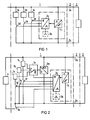
- FIG. 1 shows a sensor arrangement 1 which is connected to an evaluation circuit 3 in a catheter 2 via two lines 2a and 2b.
- the sensor arrangement 1 with the three sensors 1 a, 1 and 1 in the exemplary embodiment is accommodated in a common sensor housing, which is also to be identified by reference number 1.
- the individual sensors 1a to 1c are each connected to the lines 2a and 2b of the catheter 2 via switches 1d to 1f.
- the switches 1 to 1f are controlled by a counter 1g.
- the counter 1 can either be controlled by a clock generator 1 dedicated to the sensor arrangement 1 or via the evaluation circuit 3 and the lines 2a and 2b by a decoder 1 i.
- Lines 2a and 2b carry both the supply currents for the entire sensor arrangement 1 and the measuring currents. This is possible if the supply currents are negligibly small or constant compared to the measuring currents, so that the measuring currents can be obtained by subtracting the constant supply currents from the total current.
- the switches 1d to 1f are switched on one after the other by the counter 1g and thus the respectively assigned sensor 1a to 1c is activated, i.e. the switched on sensor 1a to 1c determines the measured value (voltage or current) on the lines 2a, 2b. Based on a measured value or the combination of several of these measured values, the evaluation circuit 3 can regulate a body function, for example the pulse frequency.
- One of the sensors mentioned can be, for example, the sensor for detecting blood oxygen saturation described in DE-PS 31 52 963 already mentioned at the beginning.
- Counter 1 can be controlled, for example, by an internal clock 1h arranged in sensor housing 1, counter 1g and clock 1 acting together as a timer circuit.
- the measurement signals must be provided with a code specific to the activated sensor so that the evaluation circuit 3 recognizes the origin of the signal.
- the evaluation circuit 3 can control the activation of the switches 1d to 1f and thus the activation of the sensors 1a to 1c.
- the evaluation circuit 3 controls a decoder 1 i via lines 2a, 2b, which in turn controls counter 1g in the exemplary embodiment.
- coded signals must be transmitted from the evaluation circuit 3 to the decoder 1.
- Pulse-phase modulation is particularly favorable for coding the signals transmitted from the evaluation circuit 3 to the decoder 1 i or from the sensors 1 to 1 c to the evaluation circuit 3 for evaluating the signal origin.
- a zero mark is set for each measuring period by a signal outside the measuring range. With this zero mark, counter 1 can be reset to zero, for example. From the distance of the received signal to the zero mark, it can then be concluded in a known clock period which of the sensors 1 to 1 c has emitted the respective signal.
- sensors 1a to 1c are assigned a common memory 1 n which can be connected to sensors 1a to 1c and has a signal converter 1m connected to its output.
- the signal converter 1m is in turn connected to the lines 2a, 2b.
- the measurement and transmission signals are separated from each other, the memory 1n storing the measured signal when a sensor 1a to 1c is activated and transmitting the measured value to the evaluation circuit 3 in time after the measurement phase of the signal converter 1m.
- an additional sensor 4 is accommodated outside the sensor housing, which is connected directly to the lead 2 a and via a switch 1 k to the lead 2 b of the catheter 2.
- the switch 1k is controlled via the decoder 1i and the counter 1g in an analogous manner to the internal sensors 1a to 1c.
- the sensor 4 can be, for example, an EKG sensor or an impedance sensor, both of which cannot be accommodated within a sensor housing.
Landscapes
- Health & Medical Sciences (AREA)
- Heart & Thoracic Surgery (AREA)
- Life Sciences & Earth Sciences (AREA)
- Cardiology (AREA)
- Nuclear Medicine, Radiotherapy & Molecular Imaging (AREA)
- General Health & Medical Sciences (AREA)
- Engineering & Computer Science (AREA)
- Biomedical Technology (AREA)
- Biophysics (AREA)
- Radiology & Medical Imaging (AREA)
- Animal Behavior & Ethology (AREA)
- Physiology (AREA)
- Public Health (AREA)
- Veterinary Medicine (AREA)
- Electrotherapy Devices (AREA)
- Measurement Of The Respiration, Hearing Ability, Form, And Blood Characteristics Of Living Organisms (AREA)
- Arrangements For Transmission Of Measured Signals (AREA)
- Media Introduction/Drainage Providing Device (AREA)
Description
- Die Erfindung betrifft eine Sensoranordnung zur Regelung implantierbarer Körperersatzteile, wobei die Sensoranordnung über einen mindestens zweipoligen Katheter mit einer Auswerteschaltung verbunden ist.
- Eine derartige Sensoranordnung für einen Herzschrittmacher ist aus der DE-PS 31 52 963 bekannt. Dabei wird mit einem in einer Herzkammer angeordneten Sensor, der über einen zweipoligen Katheter mit dem Herzschrittmacher verbunden ist, die Blutsauerstoffsättigung erfaßt. In manchen Fällen wäre die Erfassung mehrerer Meßparameter wünschenswert. Im Falle von Herzschrittmachern geben beispielsweise die Blutsauerstoffsättigung, die Bluttemperatur, der Blutdruck und der Leitwert des Blutes Aufschlüsse über die Frequenz, mit der der Herzschrittmacher arbeiten soll. Alle diese Sensoren können nicht im Herzschrittmacher selbst untergebracht werden, so daß die Meßsignale über den Katheter übertragen werden müssen. Der Katheter soll jedoch aus Gründen der Flexibilität und Zuverlässigkeit möglichst wenig Leitungen aufweisen.
- Aus der Druckschrift "Siliconix, "Analog Switch Data Book", 1976, Seite 1-152 (Figur "Industrial Control Multiplexing") sowie Seite 1-153 (Figur "An 8 Channel Mux/Demux System")" ist eine Anordnung zur Übertragung von Daten bekannt, bei der auf einer Sendeseite mehrere Eingänge einem Multiplexer zugeführt werden und ein Signal über eine Datenübertragungsleitung einem Demultiplexer auf der Empfängerseite zugeführt wird. Ferner ist eine Synchronisationsleitung zwischen Multiplexer und Demultiplexer vorgesehen. Sender- und Empfängerseite weisen jeweils getrennte Stromversorgungen auf. Eine derartige Anordnung ist für eine Sensoranordnung der oben genannten Art ungeeignet, da eine zusätzliche Stromversorgung für die Sensoren beim Einsatz im Körper höchst problematisch ist.
- Aufgabe der Erfindung ist es, mehrere Meßsignale mit einer Anordnung von mehreren Sensoren so zu übertragen, daß der Katheter möglichst wenig Leitungen benötigt und für die Sensoranordnung keine gesonderte Stromversorgung nötig ist.
- Diese Aufgabe wird erfindungsgemäß durch die Merkmale des Anspruches 1 gelöst.
- Durch den zeitlichen Versatz können die verschiedenen Meßsignale voneinander getrennt werden, ohne daß jeweils eine gesonderte Leitung des Katheters erforderlich ist.
- Die zeitlich versetzte Aktivierung der Sensoren kann auf einfache Weise dadurch erreicht werden, daß die Sensoren über Schalter an die Leitungen des Katheters angeschlossen sind und daß die Schalter von der Steuerschaltung angesteuert werden.
- In einer Ausführungsform steuert die Auswerteschaltung durch Codesignale für den Meßsignalursprung über die Steuerschaltung die Aktivierung der Sensoren. Die Aktivierung der Sensoren wird dabei zweckmäßigerweise von einem Decoder gesteuert, der von der Auswerteschaltung codierte Triggersignale als Codesignale über die Leitungen des Katheters empfängt. Der Decoder decodiert die von der Auswerteschaltung kommenden codierten Triggersignale und steuert direkt oder über eine zusätzliche Funktionsstufe - etwa einen Zähler - die Schalter an. Die Steuerschaltung ist dabei vorteilhafterweise so aufgebaut, daß sie keine eigene Zuleitung zur Auswerteschaltung benötigt, was den Einsatz eines Dreipolkatheters erfordern würde. Sie wird zweipolig parallel zu den Sensoren geschaltet, ohne deren Funktion zu beeinflußen.
- In einer alternativen Ausführungsform steuert die Steuerschaltung selbsttätig die Aktivierung der Sensoren, wobei die entstehenden Meßsignale mit für den angesteuerten Sensor spezifischen Codesignalen versehen sind.
- Dabei können die Sensoren in einfacher Weise von einer in der Steuerschaltung enthaltenen Timer-Schaltung gesteuert werden.
- Die Codesignale können Puls-Phasen-moduliert sein. Dies kann dadurch erzielt werden, daß bei jeder Meßperiode eine Null-Marke durch ein außerhalb des Meßbereiches liegendes Signal gesetzt wird und daß die Codierung durch den Abstand des codierten Signals von dieser Nullmarke erreicht wird.
- Die Codierung kann alternativ auch durch Amplituden-, Pulsdauer- oder Pulscodemodulation erfolgen.
- Jedem Sensor kann ein gemeinsamer Signalwandler mit Speicher zugeordnet sein, wobei der Speicher bei Aktivierung eines Sensors dessen Meßwert abspeichert und der abgespeicherte Meßwert nach der Meßphase vom Signalwandler in einer für die Auswerteschaltung geeigneten Form codiert und an diese übertragen wird.
- Diese Anordnung empfiehlt sich insbesondere bei Sensoren, bei denen Meß- und Sendesignal zeitlich getrennt sind.
- Ausführungsbeispiele der Erfindung werden nachfolgend anhand der Figuren 1 und 2 näher erläutert.
- Figur 1 zeigt eine Sensoranordnung 1, die in einem Katheter 2 über zwei Leitungen 2a und 2b an eine Auswerteschaltung 3 angeschlossen ist. Die Sensoranordnung 1 mit den im Ausführungsbeispiel drei Sensoren 1 a, 1 und 1 ist in einem gemeinsamen Sensorgehäuse untergebracht, das ebenfalls durch des Bezugszeichen 1 gekennzeichnet sein soll.
- Die einzelnen Sensoren 1a bis 1c sind jeweils über Schalter 1d bis 1f an die Leitungen 2a und 2b des Katheters 2 angeschlossen. Die Schalter 1 bis 1f werden von einem Zähler 1g angesteuert. Der Zähler 1 kann entweder von einem der Sensoranordnung 1 eigenen Taktgeber 1 gesteuert werden oder über die Auswerteschaltung 3 und die Leitungen 2a und 2b durch einen Decoder 1 i.
- Die Leitungen 2a und 2b führen sowohl die Versorgungsströme für die gesamte Sensoranordnung 1 als auch die Meßströme. Die ist dann möglich, wenn die Versorgungsströme gegenüber den Meßströmen vernachlässigbar klein oder konstant sind, so daß die Meßströme durch Subtraktion der konstanten Versorgungsströme vom Gesamtstrom gewonnen werden können.
- Die Schalter 1d bis 1f werden vom Zähler 1g zeitlich versetzt nacheinander eingeschaltet und damit der jeweils zugeordnete Sensor 1a bis 1c aktiviert, d.h. der eingeschaltete Sensor 1a bis 1c bestimmt den Meßwert (Spannung oder Strom) an den Leitungen 2a, 2b. Aufgrund eines Meßwertes oder der Kombination mehrerer dieser Meßwerte kann die Auswerteschaltung 3 eine Körperfunktion, beispielweise die Pulsfrequenz, regeln.
- Einer der genannten Sensoren kann beispielsweise der in der bereits eingangs genannten DE-PS 31 52 963 erläuterte Sensor zur Erfassung der Blutsauerstoffsättigung sein.
- Der Zähler 1 kann beispielsweise durch einen im Sensorgehäuse 1 angeordneten internen Takgeber 1h angesteuert werden, wobei der Zähler 1g und der Takgeber 1 zusammen als Timer-Schaltung wirken. In diesem Falle müssen die Meßsignale mit einer für den angesteuerten Sensor spezifischen Codierung versehen werden, damit die Auswerteschaltung 3 den Ursprung des Signals erkennt.
- Alternativ kann die Auswerteschaltung 3 die Ansteuerung der Schalter 1d bis 1f und damit die Aktivierung der Sensoren 1a bis 1c steuern. In diesem Fall wird durch die Auswerteschaltung 3 über die Leitungen 2a, 2b ein Decoder 1 i angesteuert, der im Ausführungsbeispiel wiederum den Zähler 1g steuert. In diesem Fall müssen codierte Signale von der Auswerteschaltung 3 zum Decoder 1 übertragen werden.
- Zur Codierung der von der Auswerteschaltung 3 an den Decoder 1 i oder von den Sensoren 1 bis 1 c an die Auswerteschaltung 3 zur Auswertung des Signalursprungs übertragenen Signale ist die Puls-Phasen-Modulation besonders günstig. Dabei wird bei jeder Meßperiode eine Nullmarke durch ein außerhalb des Meßbereichs liegendes Signal gesetzt. Mit dieser Nullmarke kann beispielsweise der Zähler 1 auf Null zurückgesetzt werden. Aus dem Abstand des empfangenen Signals zur Nullmarke kann dann bei bekannter Taktperiode geschlossen werden, welcher der Sensoren 1 bis 1 c das jeweilige Signal abgegeben hat.
- In einem Ausführungsbeispiel nach Fig. 2 ist den Sensoren 1a bis 1c ein gemeinsamer, an die Sensoren 1a bis 1c anschaltbarer Speicher 1 n zugeordnet, an dessen Ausgang ein Signalwandler 1m angeschlossen ist. Der Signalwandler 1m ist wiederum an die Leitungen 2a, 2b angeschlossen. In diesem Fall sind Meß- und Sendesignal voneinander getrennt, wobei der Speicher 1n bei Aktivierung eines Sensors 1a bis 1c das gemessene Signal abspeichert und zeitlich nach der Meßphase der Signalwandler 1 m den Meßwert in einer für die angeschlossene Auswerteschaltung 3 angepaßten Codierung an diese überträgt.
- Als Codierung durch den Signalwandler kommen praktisch alle geläufigen Modulationsverfahren wie Amplituden-, Puls-Phasen-, Pulsdauer- und Pulscode-Modulation in Frage.
- Beim Ausführungsbeispiel nach Figur 2 ist ein zusätzlicher Sensor 4 außerhalb des Sensorgehäuses untergebracht, der direkt an die Zuleitung 2a und über einen Schalter 1 k an die Zuleitung 2b des Katheters 2 angeschlossen ist.
- Der Schalter 1k wird über den Decoder 1i und über den Zähler 1g in analoger Weise wie die internen Sensoren 1a bis 1c gesteuert. Der Sensor 4 kann beispielsweise ein EKG-Sensor oder ein Impedanz-Sensor sein, die beide nicht innerhalb eines Sensorgehäuses untergebracht werden können.
Claims (10)
dadurch gekennzeichnet,
daß die Sensoren (1 bis 1c) über Schalter (1 d bis 1f) an die Leitungen (2a, 2b) des Katheters (2) angeschlossen sind und daß die Schalter (1 bis 1f) von der Steuerschaltung (1 bis 1e) angesteuert werden.
dadurch gekennzeichnet,
daß die Auswerteschaltung (3) durch die Codesignale für den Meßsignalursprung über die Steuerschaltung (1g bis 1i) die Aktivierung der Sensoren (1 bis 1f) steuert.
dadurch gekennzeichnet,
daß die Aktivierung der Sensoren (1d bis 1f) von einem Decoder (1 i) gesteuert wird, der von der Auswerteschaltung (3) codierte Triggersignale als Codesignale über die Leitungen (2a, 2b) des Katheters (2) empfängt.
dadurch gekennzeichnet,
daß die Steuerschaltung (1g, 1h) selbsttätig die Aktivierung der Sensoren (1a bis 1c) steuert und daß die entstehenden Meßsignale mit für den angesteuerten Sensor (1a bis 1c) spezifischen Codesignalen versehen sind.
dadurch gekennzeichnet,
daß die Sensoren (1a bis 1c) von einer in der Steuerschaltung enthaltenen Timerschaltung (1 h, 1 g) gesteuert werden.
dadurch gekennzeichnet,
daß die Codesignale Puls-Phasen-moduliert sind.
dadurch gekennzeichnet,
daß die Puls-Phasen-Modulation dadurch erzielt wird, daß bei jeder Meßperiode eine Null- Marke durch ein außerhalb des Meßbereiches liegendes Signal gesetzt wird und daß die Codierung durch den Abstand des codierten Signals von dieser Null-Marke erreicht wird.
dadurch gekennzeichnet,
daß die Codierung durch Amplituden-, Pulsdauer- oder Pulscodemodulation erfolgt.
dadurch gekennzeichnet,
daß jedem Sensor (1a bis 1c) ein gemeinsamer Signalwandler (1m) mit Speicher (1n) zugeordnet ist, daß der Speicher (1n) bei Aktivierung eines Sensors (1a bis 1c) dessen Meßwert abspeichert und daß der abgespeicherte Meßwert nach der Meßphase vom Signalwandler (1m) in einer für die Auswerteschaltung (3) geeigneten Form codiert und an diese übertragen wird.
Applications Claiming Priority (2)
| Application Number | Priority Date | Filing Date | Title |
|---|---|---|---|
| DE3620277 | 1986-06-16 | ||
| DE3620277 | 1986-06-16 |
Publications (3)
| Publication Number | Publication Date |
|---|---|
| EP0249680A1 EP0249680A1 (de) | 1987-12-23 |
| EP0249680B1 true EP0249680B1 (de) | 1993-07-28 |
| EP0249680B2 EP0249680B2 (de) | 2002-03-20 |
Family
ID=6303139
Family Applications (1)
| Application Number | Title | Priority Date | Filing Date |
|---|---|---|---|
| EP87102950A Expired - Lifetime EP0249680B2 (de) | 1986-06-16 | 1987-03-02 | Sensoranordnung zur Regelung implantierbarer Körperersatzteile |
Country Status (4)
| Country | Link |
|---|---|
| US (1) | US4877032A (de) |
| EP (1) | EP0249680B2 (de) |
| JP (1) | JPS63798A (de) |
| DE (1) | DE3786712D1 (de) |
Families Citing this family (48)
| Publication number | Priority date | Publication date | Assignee | Title |
|---|---|---|---|---|
| EP0444021B1 (de) * | 1987-11-13 | 1995-01-25 | BIOTRONIK Mess- und Therapiegeräte GmbH & Co Ingenieurbüro Berlin | Herzschrittmacher |
| US5336243A (en) * | 1989-11-29 | 1994-08-09 | Biotronik Mess- Und Therapiegerate Gmbh & Co., Ingenieurburo Berlin | Physiologically controlled pacemaker and pacemaker control system with detection of the spatial position of the patient |
| US5016631A (en) * | 1990-03-23 | 1991-05-21 | The Johns Hopkins University | Minimum interface biomedical monitoring system |
| US5065759A (en) * | 1990-08-30 | 1991-11-19 | Vitatron Medical B.V. | Pacemaker with optimized rate responsiveness and method of rate control |
| SE9202521D0 (sv) * | 1992-09-02 | 1992-09-02 | Siemens Elema Ab | Anordning foer stimulering av levande vaevnad |
| US5423334A (en) * | 1993-02-01 | 1995-06-13 | C. R. Bard, Inc. | Implantable medical device characterization system |
| US5593430A (en) * | 1995-01-27 | 1997-01-14 | Pacesetter, Inc. | Bus system for interconnecting an implantable medical device with a plurality of sensors |
| US6505078B1 (en) * | 1996-04-04 | 2003-01-07 | Medtronic, Inc. | Technique for adjusting the locus of excitation of electrically excitable tissue |
| WO1997037720A1 (en) * | 1996-04-04 | 1997-10-16 | Medtronic, Inc. | Living tissue stimulation and recording techniques |
| FR2796562B1 (fr) | 1996-04-04 | 2005-06-24 | Medtronic Inc | Techniques de stimulation d'un tissu vivant et d'enregistrement avec commande locale de sites actifs |
| SE9701713D0 (sv) * | 1997-05-07 | 1997-05-07 | Siemens Elema Ab | Elektrodkateter för endokardiell mapping |
| US6144866A (en) * | 1998-10-30 | 2000-11-07 | Medtronic, Inc. | Multiple sensor assembly for medical electric lead |
| US6134459A (en) * | 1998-10-30 | 2000-10-17 | Medtronic, Inc. | Light focusing apparatus for medical electrical lead oxygen sensor |
| US6731976B2 (en) | 1997-09-03 | 2004-05-04 | Medtronic, Inc. | Device and method to measure and communicate body parameters |
| US6125291A (en) * | 1998-10-30 | 2000-09-26 | Medtronic, Inc. | Light barrier for medical electrical lead oxygen sensor |
| US6248080B1 (en) | 1997-09-03 | 2001-06-19 | Medtronic, Inc. | Intracranial monitoring and therapy delivery control device, system and method |
| US6198952B1 (en) | 1998-10-30 | 2001-03-06 | Medtronic, Inc. | Multiple lens oxygen sensor for medical electrical lead |
| US6125290A (en) * | 1998-10-30 | 2000-09-26 | Medtronic, Inc. | Tissue overgrowth detector for implantable medical device |
| US6259937B1 (en) * | 1997-09-12 | 2001-07-10 | Alfred E. Mann Foundation | Implantable substrate sensor |
| US5999848A (en) * | 1997-09-12 | 1999-12-07 | Alfred E. Mann Foundation | Daisy chainable sensors and stimulators for implantation in living tissue |
| US6163723A (en) * | 1998-10-22 | 2000-12-19 | Medtronic, Inc. | Circuit and method for implantable dual sensor medical electrical lead |
| DE19930265A1 (de) * | 1999-06-25 | 2000-12-28 | Biotronik Mess & Therapieg | Elektrodenanordnung |
| US7286878B2 (en) * | 2001-11-09 | 2007-10-23 | Medtronic, Inc. | Multiplexed electrode array extension |
| US7076292B2 (en) * | 2002-04-25 | 2006-07-11 | Medtronic, Inc. | Optical communication of neurostimulation-system information |
| US7013178B2 (en) | 2002-09-25 | 2006-03-14 | Medtronic, Inc. | Implantable medical device communication system |
| US7139613B2 (en) | 2002-09-25 | 2006-11-21 | Medtronic, Inc. | Implantable medical device communication system with pulsed power biasing |
| US7069075B2 (en) * | 2002-11-22 | 2006-06-27 | Medtronic, Inc. | Subcutaneous implantable cardioverter/defibrillator |
| EP1581102A4 (de) | 2002-12-11 | 2006-12-20 | Proteus Biomedical Inc | Verfahren und system zur überwachung und behandlung von hämodynamischen parametern |
| US7204798B2 (en) * | 2003-01-24 | 2007-04-17 | Proteus Biomedical, Inc. | Methods and systems for measuring cardiac parameters |
| US7200439B2 (en) * | 2003-01-24 | 2007-04-03 | Proteus Biomedical, Inc. | Method and apparatus for enhancing cardiac pacing |
| JP4528766B2 (ja) * | 2003-01-24 | 2010-08-18 | プロテウス バイオメディカル インコーポレイテッド | 遠隔血行力学的モニタリングのためのシステム |
| US7254451B2 (en) * | 2003-11-20 | 2007-08-07 | Medtronic, Inc. | Implantable lead including sensor |
| US20050165456A1 (en) * | 2003-12-19 | 2005-07-28 | Brian Mann | Digital electrode for cardiac rhythm management |
| US7286884B2 (en) | 2004-01-16 | 2007-10-23 | Medtronic, Inc. | Implantable lead including sensor |
| US7214189B2 (en) * | 2004-09-02 | 2007-05-08 | Proteus Biomedical, Inc. | Methods and apparatus for tissue activation and monitoring |
| WO2006105474A2 (en) | 2005-03-31 | 2006-10-05 | Proteus Biomedical, Inc. | Automated optimization of multi-electrode pacing for cardiac resynchronization |
| WO2007021804A2 (en) | 2005-08-12 | 2007-02-22 | Proteus Biomedical, Inc. | Evaluation of depolarization wave conduction velocity |
| US7689289B2 (en) * | 2006-03-22 | 2010-03-30 | Medtronic, Inc. | Technique for adjusting the locus of excitation of electrically excitable tissue with paired pulses |
| US8709631B1 (en) | 2006-12-22 | 2014-04-29 | Pacesetter, Inc. | Bioelectric battery for implantable device applications |
| US8388670B1 (en) | 2007-01-16 | 2013-03-05 | Pacesetter, Inc. | Sensor/lead systems for use with implantable medical devices |
| JP4967903B2 (ja) | 2007-07-31 | 2012-07-04 | トヨタ自動車株式会社 | 静電塗装装置及び静電塗装方法 |
| WO2009131749A2 (en) | 2008-02-28 | 2009-10-29 | Proteus Biomedical, Inc. | Integrated circuit implementation and fault control system, device, and method |
| US20090287266A1 (en) * | 2008-05-13 | 2009-11-19 | Mark Zdeblick | High-voltage tolerant multiplex multi-electrode stimulation systems and methods for using the same |
| JP2012525206A (ja) | 2009-04-29 | 2012-10-22 | プロテウス バイオメディカル インコーポレイテッド | 移植可能なデバイスのためのリード線のための方法および装置 |
| JP5730872B2 (ja) | 2009-07-23 | 2015-06-10 | プロテウス デジタル ヘルス, インコーポレイテッド | 固体薄膜コンデンサ |
| US8396563B2 (en) | 2010-01-29 | 2013-03-12 | Medtronic, Inc. | Clock synchronization in an implantable medical device system |
| US8718770B2 (en) | 2010-10-21 | 2014-05-06 | Medtronic, Inc. | Capture threshold measurement for selection of pacing vector |
| US8355784B2 (en) | 2011-05-13 | 2013-01-15 | Medtronic, Inc. | Dynamic representation of multipolar leads in a programmer interface |
Family Cites Families (15)
| Publication number | Priority date | Publication date | Assignee | Title |
|---|---|---|---|---|
| US3638640A (en) * | 1967-11-01 | 1972-02-01 | Robert F Shaw | Oximeter and method for in vivo determination of oxygen saturation in blood using three or more different wavelengths |
| US3942536A (en) * | 1971-03-15 | 1976-03-09 | Mieczyslaw Mirowski | Cardioverting device having single intravascular catheter electrode system and method for its use |
| FR2166517A5 (de) * | 1971-12-28 | 1973-08-17 | Gaillard Robert | |
| JPS5926999B2 (ja) * | 1977-06-20 | 1984-07-02 | タケダ理研工業株式会社 | 多点測定装置 |
| JPS5524004A (en) * | 1978-06-22 | 1980-02-20 | Minolta Camera Kk | Oxymeter |
| US4374382A (en) * | 1981-01-16 | 1983-02-15 | Medtronic, Inc. | Marker channel telemetry system for a medical device |
| US4407288B1 (en) * | 1981-02-18 | 2000-09-19 | Mieczyslaw Mirowski | Implantable heart stimulator and stimulation method |
| DE3107128C2 (de) * | 1981-02-26 | 1984-07-05 | Heinze, Roland, Dipl.-Ing., 8000 München | Regelschaltung zur Anpassung der Stimulationsfrequenz eines Herzschrittmachers an die Belastung eines Patienten |
| DE3276673D1 (en) * | 1981-11-10 | 1987-08-06 | Sentron V O F | Catheter sensor and memory unit |
| JPS5945740A (ja) * | 1982-09-09 | 1984-03-14 | Fuji Electric Co Ltd | 測定値伝送システム |
| US4571588A (en) * | 1983-05-23 | 1986-02-18 | Varian Associates, Inc. | Scaling circuit for remote measurement system |
| US4543955A (en) * | 1983-08-01 | 1985-10-01 | Cordis Corporation | System for controlling body implantable action device |
| US4549548A (en) * | 1983-09-14 | 1985-10-29 | Vitafin N.V. | Pacemaker system with automatic event-programmed switching between unipolar and bipolar operation |
| JPS6073799A (ja) * | 1983-09-29 | 1985-04-25 | 工業技術院長 | 自律的信号伝送方式による多数検出器の接続方法 |
| US4628934A (en) * | 1984-08-07 | 1986-12-16 | Cordis Corporation | Method and means of electrode selection for pacemaker with multielectrode leads |
-
1987
- 1987-03-02 DE DE8787102950T patent/DE3786712D1/de not_active Expired - Lifetime
- 1987-03-02 EP EP87102950A patent/EP0249680B2/de not_active Expired - Lifetime
- 1987-06-11 JP JP62146189A patent/JPS63798A/ja active Pending
-
1989
- 1989-04-06 US US07/333,805 patent/US4877032A/en not_active Expired - Lifetime
Also Published As
| Publication number | Publication date |
|---|---|
| EP0249680B2 (de) | 2002-03-20 |
| US4877032A (en) | 1989-10-31 |
| EP0249680A1 (de) | 1987-12-23 |
| JPS63798A (ja) | 1988-01-05 |
| DE3786712D1 (de) | 1993-09-02 |
Similar Documents
| Publication | Publication Date | Title |
|---|---|---|
| EP0249680B1 (de) | Sensoranordnung zur Regelung implantierbarer Körperersatzteile | |
| DE69827288T2 (de) | Herzschrittmachersystem mit einzelleiter zum anschluss an einen druckwandler und eine elektrode | |
| DE69028888T2 (de) | Selbst-Testanordnung und für ein externes Programmiergerät | |
| EP0392032B1 (de) | Implantierbares medizinisches Gerät mit Mitteln zum telemetrischen Übertragen von Daten | |
| DE69529662T2 (de) | Magnetfelddetektoreinheit | |
| DE2929498C2 (de) | ||
| DE69526606T2 (de) | Kombinierte Telemetrie- und Magnetfelddetektoreinheit in einem medizinischen Implantat | |
| DE69414362T2 (de) | Verfahren zur interferenztoleranten übermittlung von herzschlagsignalen | |
| DE2803366A1 (de) | Programmierbares stimulationssystem fuer menschliches gewebe | |
| DE3117075C2 (de) | Vorhofsynchroner Herzschrittmacher | |
| EP0830878A1 (de) | Vorrichtung zur Rejektionsdiagnostik nach Organtransplantationen | |
| DE3428975A1 (de) | Atmungsgesteuerter herzschrittmacher | |
| DE4013048B4 (de) | Anordnung zur Gewebestimulation | |
| DE4223657A1 (de) | Drahtloser schalter fuer einen telemetrischen empfaenger | |
| DE3329049C2 (de) | ||
| DE69936113T2 (de) | Schaltsteuerung für drahtlose Übertragung von physiologischen Messungen | |
| DE3220930A1 (de) | Zweiwegkommunikationssystem zwischen einem implantierbaren elektrischen stimulator und einer externen kontrolleinheit | |
| EP0004625B1 (de) | Elektromedizinisches Gerät zur Abnahme und Verarbeitung von elektrischen physiologischen Signalen | |
| DE2908187A1 (de) | Vorrichtung zur anlieferung von fuer herzsignale kennzeichnenden akustischen signalen | |
| EP0557550A1 (de) | Frequenzadaptierender Herzschrittmacher | |
| DE3821608A1 (de) | Schaltungsanordnung zur uebertragung mindestens eines veraenderlichen messwertes von jeweils einem der raeder eines fahrzeuges zu einer zentralen ueberwachungseinheit | |
| DE2826189A1 (de) | Verfahren zur ueberwachung und veraenderlichen steuerung eines eingepflanzten schrittmachers | |
| EP1262143A1 (de) | Verfahren und Speichervorrichtung zur Speicherung von Herzrhythmusinformation | |
| DE69632673T2 (de) | Herzschrittmacher mit Detektion der evozierten Reaktion | |
| DE2801209C3 (de) | Datenerfassungssystem |
Legal Events
| Date | Code | Title | Description |
|---|---|---|---|
| PUAI | Public reference made under article 153(3) epc to a published international application that has entered the european phase |
Free format text: ORIGINAL CODE: 0009012 |
|
| AK | Designated contracting states |
Kind code of ref document: A1 Designated state(s): DE FR GB IT NL SE |
|
| 17P | Request for examination filed |
Effective date: 19880125 |
|
| 17Q | First examination report despatched |
Effective date: 19900926 |
|
| GRAA | (expected) grant |
Free format text: ORIGINAL CODE: 0009210 |
|
| AK | Designated contracting states |
Kind code of ref document: B1 Designated state(s): DE FR GB IT NL SE |
|
| PG25 | Lapsed in a contracting state [announced via postgrant information from national office to epo] |
Ref country code: SE Effective date: 19930728 |
|
| REF | Corresponds to: |
Ref document number: 3786712 Country of ref document: DE Date of ref document: 19930902 |
|
| ITF | It: translation for a ep patent filed | ||
| ET | Fr: translation filed | ||
| GBT | Gb: translation of ep patent filed (gb section 77(6)(a)/1977) |
Effective date: 19931019 |
|
| PLBI | Opposition filed |
Free format text: ORIGINAL CODE: 0009260 |
|
| 26 | Opposition filed |
Opponent name: BIOTRONIK MESS- UND THERAPIEGERAETE GMBH & CO INGE Effective date: 19940428 |
|
| NLR1 | Nl: opposition has been filed with the epo |
Opponent name: BIOTRONIK MESS- UND THERAPIEGERAETE GMBH & CO. |
|
| RAP2 | Party data changed (patent owner data changed or rights of a patent transferred) |
Owner name: PACESETTER AB |
|
| NLT2 | Nl: modifications (of names), taken from the european patent patent bulletin |
Owner name: PACESETTER AB |
|
| REG | Reference to a national code |
Ref country code: GB Ref legal event code: 732E |
|
| REG | Reference to a national code |
Ref country code: FR Ref legal event code: TP |
|
| NLS | Nl: assignments of ep-patents |
Owner name: PACESETTER AB |
|
| PLAW | Interlocutory decision in opposition |
Free format text: ORIGINAL CODE: EPIDOS IDOP |
|
| APAC | Appeal dossier modified |
Free format text: ORIGINAL CODE: EPIDOS NOAPO |
|
| APAE | Appeal reference modified |
Free format text: ORIGINAL CODE: EPIDOS REFNO |
|
| APAC | Appeal dossier modified |
Free format text: ORIGINAL CODE: EPIDOS NOAPO |
|
| PGFP | Annual fee paid to national office [announced via postgrant information from national office to epo] |
Ref country code: GB Payment date: 19980220 Year of fee payment: 12 |
|
| RAP2 | Party data changed (patent owner data changed or rights of a patent transferred) |
Owner name: PACESETTER AB |
|
| PGFP | Annual fee paid to national office [announced via postgrant information from national office to epo] |
Ref country code: NL Payment date: 19980320 Year of fee payment: 12 |
|
| NLT2 | Nl: modifications (of names), taken from the european patent patent bulletin |
Owner name: PACESETTER AB |
|
| PG25 | Lapsed in a contracting state [announced via postgrant information from national office to epo] |
Ref country code: GB Free format text: LAPSE BECAUSE OF NON-PAYMENT OF DUE FEES Effective date: 19990302 |
|
| PG25 | Lapsed in a contracting state [announced via postgrant information from national office to epo] |
Ref country code: NL Free format text: LAPSE BECAUSE OF NON-PAYMENT OF DUE FEES Effective date: 19991001 |
|
| NLV4 | Nl: lapsed or anulled due to non-payment of the annual fee |
Effective date: 19991001 |
|
| RAP2 | Party data changed (patent owner data changed or rights of a patent transferred) |
Owner name: ST. JUDE MEDICAL AB |
|
| PLBQ | Unpublished change to opponent data |
Free format text: ORIGINAL CODE: EPIDOS OPPO |
|
| PLAB | Opposition data, opponent's data or that of the opponent's representative modified |
Free format text: ORIGINAL CODE: 0009299OPPO |
|
| R26 | Opposition filed (corrected) |
Opponent name: BIOTRONIK MESS- UND THERAPIEGERAETE GMBH & CO INGE Effective date: 19940428 |
|
| APAC | Appeal dossier modified |
Free format text: ORIGINAL CODE: EPIDOS NOAPO |
|
| PLAW | Interlocutory decision in opposition |
Free format text: ORIGINAL CODE: EPIDOS IDOP |
|
| PUAH | Patent maintained in amended form |
Free format text: ORIGINAL CODE: 0009272 |
|
| STAA | Information on the status of an ep patent application or granted ep patent |
Free format text: STATUS: PATENT MAINTAINED AS AMENDED |
|
| 27A | Patent maintained in amended form |
Effective date: 20020320 |
|
| AK | Designated contracting states |
Kind code of ref document: B2 Designated state(s): DE FR GB IT NL SE |
|
| ET3 | Fr: translation filed ** decision concerning opposition | ||
| PG25 | Lapsed in a contracting state [announced via postgrant information from national office to epo] |
Ref country code: IT Free format text: LAPSE BECAUSE OF NON-PAYMENT OF DUE FEES;WARNING: LAPSES OF ITALIAN PATENTS WITH EFFECTIVE DATE BEFORE 2007 MAY HAVE OCCURRED AT ANY TIME BEFORE 2007. THE CORRECT EFFECTIVE DATE MAY BE DIFFERENT FROM THE ONE RECORDED. Effective date: 20050302 |
|
| APAH | Appeal reference modified |
Free format text: ORIGINAL CODE: EPIDOSCREFNO |
|
| PGFP | Annual fee paid to national office [announced via postgrant information from national office to epo] |
Ref country code: FR Payment date: 20060228 Year of fee payment: 20 |
|
| PGFP | Annual fee paid to national office [announced via postgrant information from national office to epo] |
Ref country code: DE Payment date: 20060327 Year of fee payment: 20 |