EP0249208A1 - Schiffsantriebsanlage mit zwei Verstellpropellern - Google Patents
Schiffsantriebsanlage mit zwei Verstellpropellern Download PDFInfo
- Publication number
- EP0249208A1 EP0249208A1 EP87108374A EP87108374A EP0249208A1 EP 0249208 A1 EP0249208 A1 EP 0249208A1 EP 87108374 A EP87108374 A EP 87108374A EP 87108374 A EP87108374 A EP 87108374A EP 0249208 A1 EP0249208 A1 EP 0249208A1
- Authority
- EP
- European Patent Office
- Prior art keywords
- propeller
- gear
- ship
- clutches
- blocks
- Prior art date
- Legal status (The legal status is an assumption and is not a legal conclusion. Google has not performed a legal analysis and makes no representation as to the accuracy of the status listed.)
- Granted
Links
- 230000005540 biological transmission Effects 0.000 claims abstract description 12
- 230000008878 coupling Effects 0.000 description 3
- 238000010168 coupling process Methods 0.000 description 3
- 238000005859 coupling reaction Methods 0.000 description 3
- 238000000418 atomic force spectrum Methods 0.000 description 2
- 238000010276 construction Methods 0.000 description 1
- 238000009826 distribution Methods 0.000 description 1
- 239000000446 fuel Substances 0.000 description 1
- 238000009434 installation Methods 0.000 description 1
Images




Classifications
-
- B—PERFORMING OPERATIONS; TRANSPORTING
- B63—SHIPS OR OTHER WATERBORNE VESSELS; RELATED EQUIPMENT
- B63H—MARINE PROPULSION OR STEERING
- B63H23/00—Transmitting power from propulsion power plant to propulsive elements
- B63H23/02—Transmitting power from propulsion power plant to propulsive elements with mechanical gearing
- B63H23/10—Transmitting power from propulsion power plant to propulsive elements with mechanical gearing for transmitting drive from more than one propulsion power unit
- B63H23/18—Transmitting power from propulsion power plant to propulsive elements with mechanical gearing for transmitting drive from more than one propulsion power unit for alternative use of the propulsion power units
-
- B—PERFORMING OPERATIONS; TRANSPORTING
- B63—SHIPS OR OTHER WATERBORNE VESSELS; RELATED EQUIPMENT
- B63H—MARINE PROPULSION OR STEERING
- B63H3/00—Propeller-blade pitch changing
- B63H3/10—Propeller-blade pitch changing characterised by having pitch control conjoint with propulsion plant control
-
- B—PERFORMING OPERATIONS; TRANSPORTING
- B63—SHIPS OR OTHER WATERBORNE VESSELS; RELATED EQUIPMENT
- B63H—MARINE PROPULSION OR STEERING
- B63H5/00—Arrangements on vessels of propulsion elements directly acting on water
- B63H5/07—Arrangements on vessels of propulsion elements directly acting on water of propellers
- B63H5/08—Arrangements on vessels of propulsion elements directly acting on water of propellers of more than one propeller
Definitions
- the invention relates to a ship propulsion device with at least two motors for driving two variable propellers and at least two auxiliary machines, each propeller being assigned a gear block.
- Ships that require the greatest propulsion power for short periods of time, but are operated with less than 50% power or less than 70% of the possible ship speed during long periods of operation, are predominantly equipped with two or four engines.
- Ship types of this type include, for example, supply ships, cruise ships, passenger ships and tugs. Of all the engines, only two are predominantly in operation.
- Power take-offs for example for generators, can also only be driven by the control and port machine assigned to them.
- the applicant has also proposed the installation of more than two motors with the same or different outputs, one half of which is assigned to a propeller. Both propellers can be driven by the motor or motors on one side of the propeller, even at the respective operational propeller speed. Under this condition, the driving profile can then be divided into several areas.
- parallel operation of the generators (auxiliary machines) installed on each propeller side by one or both of the starboard or port engines was not possible. Despite this arrangement, it was also not possible to do without a clutch in the connecting block of the transmission blocks.
- the invention is based on the object of designing a ship propulsion system according to the preamble of claim 1 in such a way that optimal use is made of the total installed power distributed to the individual drive motors, taking into account the very different driving profile of the ship, the engine and propeller characteristics and the different use of generators is guaranteed.
- the invention as a solution to this problem is characterized in that a generator gear block, consisting of generators, which are connected in parallel by shafts via gear wheels and are connected in a slip-free manner, is arranged between the gear blocks, the generator gear block optionally having one of the motors -Propeller gear blocks, can be connected to both motor-propeller gear blocks for one or two driving motors or to both motor-propeller gear blocks for one or two driving motors and propellers switched off.
- the invention offers the possibility of driving both propellers at an economical speed by means of a motor, using the propeller map and thus with the best efficiency.
- the required partial output of the engine that is not connected to the generator transmission block can be driven in a fuel-efficient manner via the engine characteristic curve.
- the entire drive system consists of two gear blocks arranged in mirror image.
- the total installed power is distributed over two or four drive motors M I - M IV .
- the gear blocks are interconnected by a generator gear block G1, W2, S4, W8, W9.
- the clutches K 1 can also be placed according to FIGS. 1A, 3A into the transmission drive shafts W 2 of the connecting stages.
- the connection of the generator gear block to the respective motor-propeller gear block is made via the clutch K1, connecting stages S3 and the shafts W1.
- a motor is supposed to drive a propeller, its power is routed via the clutch K 1 into the generator gear block and additionally via the clutch K 2 into the associated propeller. In this case, the other motor drives only the assigned propeller via the activated clutch K2.
- the starboard engine must be disconnected from the system.
- the clutches belonging to the starboard engine K1 and K2 are switched off
- the power of the port engine is transmitted in this case by switching on the port clutches K1, K3 and the starboard clutch K3.
- FIGS. 3 and 3A in deviation from the device according to FIGS. 1 and 1A, two additional drive motors are provided, one for each side of the ship. They are the M II and M III motors. The additional motors are arranged so that they bring their performance directly into the same reduction step S1, which are already available for the motors M I and M IV .
- the switching options and corresponding force profiles for the devices according to FIGS. 3 and 3A can be found in the table according to FIG.
- the most economical machine combinations with power distributions can be determined for different power consumption of the two adjustable propellers or for different driving speeds, taking into account the pitch of the propeller blades, so that the system can be driven extremely energy-saving over the entire driving profile.
Landscapes
- Engineering & Computer Science (AREA)
- Chemical & Material Sciences (AREA)
- Combustion & Propulsion (AREA)
- Mechanical Engineering (AREA)
- Ocean & Marine Engineering (AREA)
- Aviation & Aerospace Engineering (AREA)
- Structure Of Transmissions (AREA)
- Connection Of Motors, Electrical Generators, Mechanical Devices, And The Like (AREA)
Abstract
Description
- Die Erfindung betrifft eine Schiffsantriebseinrichtung mit wenigstens zwei Motoren zum Antrieb zweier Verstellpropeller und wenigstens zweier Hilfsmaschinen, wobei jedem Propeller ein Getriebeblock zugeordnet ist.
- Bei Schiffen mit sehr unterschiedlichen Fahrprofilen bezüglich Schiffsgeschwindigkeit, Manövrierfähigkeit und zugehörigem, sehr unterschiedlichen Elektroenergiebedarf ist eine optimale Ausnutzung des zur Verfügung stehenden Brennstoffes für die Antriebsmotoren sowie deren Betriebsstunden je Fahrroute von größter Wichtigkeit.
- Schiffe, die über kurze Zeiten größte Antriebsleistungen erfordern, während langer Einsatzzeiten jedoch mit weniger als 50% Leistung oder weniger als 70% der möglichen Schiffsgeschwindigkeit betrieben werden, sind vorwiegend mit zwei oder vier Motoren ausgerüstet. Zu Schiffstypen dieser Art zählen beispielsweise Versorgungsschiffe, Kreuzfahrt-, Passagierschiffe und Schlepper. Von allen Motoren sind überwiegend nur zwei Motoren im Betrieb.
- Kennzeichnend für diese Anlagen ist, daß die Hälfte der installierten Motoren jeweils einem Propellerstrang zugeordnet sind, so daß voneinander unabhängige Backbord- und Steuerbordanlagen vorhanden sind.
- Auch Nebenabtriebe, beispielsweise für Generatoren, sind nur von der ihnen zugeordneten Steuer- und Backbordmaschine antreibbar.
- Durch die Anmelderin wurde auch die Installation von mehr als zwei Motoren mit gleichen oder unterschiedlichen Leistungen vorgeschlagen, von welchen jeweils eine Hälfte einem Propeller zugeordnet ist. Dabei können beide Propeller von dem oder den Motoren einer Propellerseite angetrieben werden, auch bei der jeweiligen betriebsbedingten Propellerdrehzahl. Unter dieser Voraussetzung kann dann das Fahrprofil in mehrere Bereiche unterteilt werden. Ein Parallelbetrieb der je Propellerseite installierten Generatoren (Hilfsmaschinen) durch einen oder beide der Steuerbord- oder Backbordmotoren war bisher nicht mögich. Es war auch nicht möglich, trotz dieser Anordnung ohne eine Schaltkupplung im Verbindungsstrang der Getriebeblöcke auszukommen.
- Es ist lediglich durch die niederländische Patentanmeldung 17 79 04 bei Kriegsschiffen mit Doppelschrauben und zwei Antriebsmotoren bekannt, eine der Antriebsmaschinen stillzusetzen und die andere zum Antrieb beider Schrauben zu verwenden oder beide Antriebsmaschinen auf beide oder eine der Schrauben arbeiten zu lassen, un die Manövrierfähigkeit zu erhöhen. Erreicht werden diese Möglichkeiten durch die Verwendung von Verbindungsgetrieben zwischen den Antriebswellen der Antriebsmaschinen. Die Verbindungsgetriebe sind über Schaltkupplungen zu- oder abschaltbar. Diese Lösung läßt sich jedoch für Antriebsanlagen bei Doppelschraubern mit wenigstens zwei Antriebsmaschinen nicht verwenden.
- Der Erfindung liegt die Aufgabe zu Grunde, eine Schiffsantriebsanlage nach dem Gattungsbegriff des Patentanspruchs 1 so zu gestalten, daß eine optimale Ausnutzung der gesamten installierten, sich auf die einzelnen Antriebsmotoren verteilenden Leistungen unter Berücksichtigung des sehr unterschiedlichen Fahrprofils des Schiffes, der Motor- und Propellerkennfelder und des unterschiedlichen Einsatzes von Generatoren gewährleistet wird. Insbesondere soll es möglich sein, unabhängig von der Zuordnung der Einrichtungsteile, die von der Schiffskonstruktion und den Platzverhältnissen im Maschinenraum bestimmt wird, von jedem Getriebeblock die Generatoren parallel anzutreiben.
Die Erfindung als Lösung dieser Aufgabe zeichnet sich dadurch aus, daß zwischen den Getriebeblöcken ein Generatoren-Getriebeblock, bestehend aus Generatoren, die durch Wellen über Zahnräder parallel geschaltet und schlupffrei verbunden sind, angeordnet ist, wobei der Generatoren-Getriebeblock wahlweise jeweils mit einem der Motoren-Propeller-Getriebeblöcke, mit beiden Motor-Propeller-Getriebeblöcken bei einem oder zwei treibenden Motoren oder mit beiden Motor-Properller-Getriebeblöcken bei einem oder zwei treibenden Motoren und abgeschalteten Propellern verbindbar ist. - Weitere, die Erfindung vorteilhaft gestaltende Merkmale sind in den Unteransprüchen angegeben.
- Die Erfindung bietet die Möglichkeit, durch einen Motor beide Propeller mit ökonomischer Drehzahl anzutreiben und zwar unter Ausnutzung des Propellerkennfeldes und somit mit bestem Wirkungsgrad. Dabei kann die erforderliche Teilleistung des nicht mit dem Generatoren-Getriebeblock verbundenen Motors über die Motorkennlinie brennstoffgünstig gefahren werden.
- In der Zeichnung ist ein Ausführungsbeispiel der Erfindung rein schematisch dargestellt und nachstehend erläutert. Es zeigen:
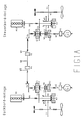
- Fig. 1 die Einrichtungsanordnung für die Übertragung der Antriebsleistungen von zwei Motoren (jeweils 1 Motor achsversetzt zu einem Propeller) mit einem Generatoren-Getriebeblock auf zwei Propeller,
- Fig. 1A die Anordnung gemäß Fig. 1, jedoch mit einer anderen Plazierung der Zuschaltkupplungen für den Generatoren-Getriebeblock,
- Fig. 2 tabellarische Übersichten für Fahrmöglichkeiten mit einer Antriebsanlage gemäß Figuren 1 und 1A,
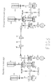
- Fig. 3 eine Antriebsanordnung wie Fig 1, jedoch mit einem zusätzlichen Antriebsmotor für jede Getriebeblockseite,
- Fig. 3A die Anordnung gemäß Fig. 3, jedoch mit einer anderen Plazierung der Zuschaltkupplungen für den Generatoren-Getriebeblock,
- Fig. 4 tabellarische Übersichten für Fahrmöglichkeiten einer Antriebsanordnung gemäß Fig 3 und 3A.
- Die in den Figuren der Zeichnungen verwendeten Bezugszeichen bedeuten im Einzelnen: MI, MII Antriebsmotoren der Backbordseite
MIII, MIV Antriebsmotoren der Steuerbordseite
K₁ Zuschaltkupplungen für den Generatoren-Getriebeblock
K₂, K₃ Schaltkupplungen der Getriebeschaltstufen
K₄ Schaltkupplungen zusätzlicher Antriebsmotoren
W₁, W₂ Getriebeantriebswellen
W₃ Propellerwellen
W₄, W₅, W₆ Kupplungshohlwellen
W₇ Hilfsmaschinenabtriebswelle
W₈ Zwischenwelle
W₉ Kegelradwelle
S₁ Getriebestufe der Propellerwelle
S₂ Verbindungsstufe zwischen den Kupplungen K₂, K₃
S₃ Verbindungsstufe zwischen den Getriebeantriebswellen W₁, W₂
S₄ Kegelradstufe zur Verbindung der Getriebeblöcke miteinander
G₁ Stromgeneratoren als Hilfsmaschinen im Nebenantrieb
K₆ nichtschaltbare Ausgleichskupplungen
K₇ nichtschaltbare Ausgleichskupplungen an den Antriebsmaschinen MI bis MIV
- Bei den Ausführungsbeispielen gemäß Figuren 1, 1A, 3 und 3A besteht die gesamte Antriebsanlage aus zwei spiegelbildlich angeordneten Getriebeblöcken. Die gesamte installierte Leistung ist auf zwei bzw. vier Antriebsmotoren MI - MIV verteilt.
- Die Getriebeblöcke sind miteinander durch einen Generatoren-Getriebeblock G₁, W₂, S₄, W₈, W₉ verbunden. Die Kupplungen K₁ können auch gemäß Figur 1A, 3A indie Getriebeantriebswellen W₂ der Verbindungsstufen gesetzt werden.
Die Zuschaltung des Generatoren-Getriebeblocks zu dem jeweiligen Motor-Propeller-Getriebeblock erfolgt über die Schaltkupplung K₁, Verbindungsstufen S₃ und die Wellen W₁. Sobald ein Motor einen Propeller antreiben soll, wird seine Leistung über die Kupplung K₁ in den Generatoren-Getriebeblock geleitet und zusätzlich über die Kupplung K₂ in den zugehörigen Propeller. In diesem Falle treibt der andere Motor über die zugeschaltete Kupplung K₂ nur den zugeordneten Propeller an. Diese Schaltmöglichkeiten sind wechselweise möglich. - Falls einer der Motoren, beispielsweise der Backbordmotor sowohl beide Propeller als auch die Generatoren antreibt, muß der Steuerbordmotor vom System getrennt werden. In diesem Falle sind die zum Steuerbordmotor gehörenden Schaltkupplungen K₁ und K₂ ausgeschaltet
Die Leistung des Backbordmotors wird in diesem Falle durch Einschalten der backbordseitigen Kupplungen K₁, K₃ und der steuerbordseitigen Kupplung K₃ übertragen. Diese Schaltmöglichkeiten sind auch in umgekehrter Richtung, d. h. Antrieb beider Propeller und der Generatoren über den Steuerbordmotor und Trennen des Backboadmotors vom System möglich. - Sobald nur die Generatoren bei abgeschalteten Propellern be trieben werden sollen, genügt der Einsatz eines Motors, der lediglich durch Zuschalten der ihm zugeordneten Kupplung K₁ seine Leistung in den Generatoren-Getriebeblock gibt.
- Die Schaltmöglichkeiten und entsprechenden Kraftverläufe für die Antriebsanlagen mit Kupplungsanordnung gemäß Figuren 1 und 1A können den Tabellen der Figur 2 entnommen werden.
- In den Figuren 3 und 3A sind in Abweichung von der Einrichtung nach den Figuren 1 und 1A zwei zusätzliche Antriebsmotoren, für jede Schiffsseite einer, vorgesehen. Es sind die Motoren MII und MIII. Die zusätzlichen Motoren sind so angeordnet, daß sie ihre Leistungen unmittelbar in die gleiche Untersetzungsstufe S₁ bringen, die bereits für die Motoren MI bzw. MIV vorhanden sind.
Die Schaltmöglichkeiten und entsprechenden Kraftverläufe für die Einrichtungen nach den Figuren 3 und 3A sind der Tabelle gemäß Figur 4 zu entnehmen. - Mit den erfindungsgemäß ausgestalteten Antriebseinrichtungen können für verschiedene Leistungsaufnahmen der beiden Verstellpropeller bzw. für unterschiedliche Fahrgeschwindigkeiten die wirtschaftlichsten Maschinenkombinationen mit Leistungsaufteilungen unter Berücksichtigung der Blattsteigungen der Propeller bestimmt werden, so daß die Anlage über das gesamte Fahrprofil äußerste energiesparend gefahren werden kann.
- Durch die erfindungsgemäße Einrichtung können größere Generatorleistungen für einen Parallelbetrieb installiert werden. Ein Parallelbetrieb der Motoren beider Propellerseiten oder ein doppeltes elektrisches Bordnetz können vermieden werden.
Claims (7)
Applications Claiming Priority (2)
| Application Number | Priority Date | Filing Date | Title |
|---|---|---|---|
| DE3619545 | 1986-06-13 | ||
| DE19863619545 DE3619545A1 (de) | 1986-06-13 | 1986-06-13 | Schiffsantriebsanlage mit zwei verstellprobellern |
Publications (2)
| Publication Number | Publication Date |
|---|---|
| EP0249208A1 true EP0249208A1 (de) | 1987-12-16 |
| EP0249208B1 EP0249208B1 (de) | 1989-08-16 |
Family
ID=6302728
Family Applications (1)
| Application Number | Title | Priority Date | Filing Date |
|---|---|---|---|
| EP87108374A Expired EP0249208B1 (de) | 1986-06-13 | 1987-06-10 | Schiffsantriebsanlage mit zwei Verstellpropellern |
Country Status (2)
| Country | Link |
|---|---|
| EP (1) | EP0249208B1 (de) |
| DE (2) | DE3619545A1 (de) |
Cited By (5)
| Publication number | Priority date | Publication date | Assignee | Title |
|---|---|---|---|---|
| WO2001056877A1 (de) * | 2000-02-04 | 2001-08-09 | Zf Friedrichshafen Ag | Zweimotoren-schiffsantriebsanlage |
| EP2426049A1 (de) * | 2010-09-07 | 2012-03-07 | Reintjes GmbH | Schiffsgetriebe |
| CN104149962A (zh) * | 2014-07-24 | 2014-11-19 | 杭州前进齿轮箱集团股份有限公司 | 一种用于测试柴油机性能的专用齿轮箱 |
| WO2019219305A1 (de) * | 2018-05-14 | 2019-11-21 | Schottel Gmbh | Antriebssystem eines schiffes |
| CN113474251A (zh) * | 2019-03-11 | 2021-10-01 | 斯维特泽尔公司 | 用于连接和驱动船舶的至少两个传动系的轴联动机构 |
Citations (1)
| Publication number | Priority date | Publication date | Assignee | Title |
|---|---|---|---|---|
| FR586050A (fr) * | 1923-09-24 | 1925-03-13 | Fiat Spa | Système d'installation de groupes moteurs-propulseurs sur des bateaux |
Family Cites Families (3)
| Publication number | Priority date | Publication date | Assignee | Title |
|---|---|---|---|---|
| CH379313A (de) * | 1960-08-04 | 1964-06-30 | Schweizerische Lokomotiv | Getriebeanlage für ein Zweischraubenschiff |
| CH632963A5 (de) * | 1978-10-13 | 1982-11-15 | Maag Zahnraeder & Maschinen Ag | Antriebsanlage fuer schiffe. |
| DE2927386B1 (de) * | 1979-07-04 | 1981-01-29 | Mannesmann Ag | Schiffsgetriebe mit einer Nebenabtriebswelle |
-
1986
- 1986-06-13 DE DE19863619545 patent/DE3619545A1/de active Granted
-
1987
- 1987-06-10 EP EP87108374A patent/EP0249208B1/de not_active Expired
- 1987-06-10 DE DE8787108374T patent/DE3760444D1/de not_active Expired
Patent Citations (1)
| Publication number | Priority date | Publication date | Assignee | Title |
|---|---|---|---|---|
| FR586050A (fr) * | 1923-09-24 | 1925-03-13 | Fiat Spa | Système d'installation de groupes moteurs-propulseurs sur des bateaux |
Cited By (9)
| Publication number | Priority date | Publication date | Assignee | Title |
|---|---|---|---|---|
| WO2001056877A1 (de) * | 2000-02-04 | 2001-08-09 | Zf Friedrichshafen Ag | Zweimotoren-schiffsantriebsanlage |
| US6688924B2 (en) | 2000-02-04 | 2004-02-10 | Zf Friedrichshafen Ag | Two-engine propulsion system for a ship |
| EP2426049A1 (de) * | 2010-09-07 | 2012-03-07 | Reintjes GmbH | Schiffsgetriebe |
| US8715022B2 (en) | 2010-09-07 | 2014-05-06 | Reintjes Gmbh | Marine vessel transmission |
| CN104149962A (zh) * | 2014-07-24 | 2014-11-19 | 杭州前进齿轮箱集团股份有限公司 | 一种用于测试柴油机性能的专用齿轮箱 |
| WO2019219305A1 (de) * | 2018-05-14 | 2019-11-21 | Schottel Gmbh | Antriebssystem eines schiffes |
| US20210214063A1 (en) * | 2018-05-14 | 2021-07-15 | Schottel Gmbh | Drive system for a ship |
| US11866143B2 (en) | 2018-05-14 | 2024-01-09 | Schottel Gmbh | Drive system for a ship |
| CN113474251A (zh) * | 2019-03-11 | 2021-10-01 | 斯维特泽尔公司 | 用于连接和驱动船舶的至少两个传动系的轴联动机构 |
Also Published As
| Publication number | Publication date |
|---|---|
| EP0249208B1 (de) | 1989-08-16 |
| DE3619545A1 (de) | 1987-12-17 |
| DE3760444D1 (en) | 1989-09-21 |
| DE3619545C2 (de) | 1990-06-28 |
Similar Documents
| Publication | Publication Date | Title |
|---|---|---|
| DE4432483A1 (de) | Zusatzantrieb für Seeschiffe | |
| EP3854616B1 (de) | Getriebe mit nebenabtrieb | |
| DE2758555C2 (de) | Zweistufiges Schaltgetriebe für den Antrieb eines Generators von einer Schiffsantriebsanlage | |
| DE2850963B1 (de) | Antriebsanlage fuer Schiffe | |
| DE102020101667A1 (de) | Antriebsstrang für ein Kraftfahrzeug | |
| EP0249208B1 (de) | Schiffsantriebsanlage mit zwei Verstellpropellern | |
| DE3331480A1 (de) | Schiffsantriebsanlage | |
| DE2927386B1 (de) | Schiffsgetriebe mit einer Nebenabtriebswelle | |
| EP0246631B1 (de) | Schiffsantriebsanlage | |
| DE102020000462A1 (de) | Modularer Getriebebaukasten für ein Kraftfahrzeug | |
| EP0428783A1 (de) | Spielfreier Mehrritzelantrieb | |
| EP3793893B1 (de) | Antriebssystem eines schiffes | |
| CH638737A5 (de) | Verfahren zum betrieb einer schiffsantriebsanlage. | |
| DE10005538A1 (de) | Bootsantrieb | |
| DE3623980A1 (de) | Schiffsantriebsanlage mit zwei verstellpropellern | |
| DE3617425C2 (de) | ||
| DE4441604C2 (de) | Schiffspropulsionsanlage mit zwei koaxialen, gegenläufig rotierenden Propellern | |
| DE4032735A1 (de) | Stromerzeugungsanlage an bord von schiffen | |
| EP4722566A2 (de) | Schaltstrategie für ein getriebe | |
| DE8615676U1 (de) | Schiffsantriebsanlage mit zwei Verstellpropellern | |
| DE2228956A1 (de) | Antriebsanlage fuer schiffe, insbesondere schnellboote | |
| DE102019208548B4 (de) | Getriebe für einen Ruderpropellerantrieb und Ruderpropellerantrieb | |
| DE19517262A1 (de) | Kraftfahrzeug mit einem Nebenverbraucher, insbesondere Feuerwehrfahrzeug mit einer Löschpumpe | |
| DE102004026332A1 (de) | Schienenfahrzeugantriebssystem und Verfahren zur Anpassung einer Getriebebaueinheit an das Kennfeld einer Gasturbine in einem Schienenfahrzeugantriebssystem | |
| DE8600470U1 (de) | Schiffsantriebseinrichtung mit zwei Verstellpropellern |
Legal Events
| Date | Code | Title | Description |
|---|---|---|---|
| PUAI | Public reference made under article 153(3) epc to a published international application that has entered the european phase |
Free format text: ORIGINAL CODE: 0009012 |
|
| 17P | Request for examination filed |
Effective date: 19870629 |
|
| AK | Designated contracting states |
Kind code of ref document: A1 Designated state(s): CH DE FR GB IT LI NL |
|
| 17Q | First examination report despatched |
Effective date: 19890109 |
|
| GRAA | (expected) grant |
Free format text: ORIGINAL CODE: 0009210 |
|
| AK | Designated contracting states |
Kind code of ref document: B1 Designated state(s): CH DE FR GB IT LI NL |
|
| ITF | It: translation for a ep patent filed | ||
| GBT | Gb: translation of ep patent filed (gb section 77(6)(a)/1977) | ||
| REF | Corresponds to: |
Ref document number: 3760444 Country of ref document: DE Date of ref document: 19890921 |
|
| ET | Fr: translation filed | ||
| PLBE | No opposition filed within time limit |
Free format text: ORIGINAL CODE: 0009261 |
|
| STAA | Information on the status of an ep patent application or granted ep patent |
Free format text: STATUS: NO OPPOSITION FILED WITHIN TIME LIMIT |
|
| 26N | No opposition filed | ||
| ITTA | It: last paid annual fee | ||
| PGFP | Annual fee paid to national office [announced via postgrant information from national office to epo] |
Ref country code: NL Payment date: 19920630 Year of fee payment: 6 |
|
| PGFP | Annual fee paid to national office [announced via postgrant information from national office to epo] |
Ref country code: FR Payment date: 19930527 Year of fee payment: 7 |
|
| PGFP | Annual fee paid to national office [announced via postgrant information from national office to epo] |
Ref country code: GB Payment date: 19930528 Year of fee payment: 7 |
|
| PG25 | Lapsed in a contracting state [announced via postgrant information from national office to epo] |
Ref country code: NL Effective date: 19940101 |
|
| NLV4 | Nl: lapsed or anulled due to non-payment of the annual fee | ||
| PG25 | Lapsed in a contracting state [announced via postgrant information from national office to epo] |
Ref country code: GB Effective date: 19940610 |
|
| GBPC | Gb: european patent ceased through non-payment of renewal fee |
Effective date: 19940610 |
|
| PG25 | Lapsed in a contracting state [announced via postgrant information from national office to epo] |
Ref country code: FR Effective date: 19950228 |
|
| REG | Reference to a national code |
Ref country code: FR Ref legal event code: ST |
|
| PGFP | Annual fee paid to national office [announced via postgrant information from national office to epo] |
Ref country code: CH Payment date: 20000515 Year of fee payment: 14 |
|
| PGFP | Annual fee paid to national office [announced via postgrant information from national office to epo] |
Ref country code: DE Payment date: 20000526 Year of fee payment: 14 |
|
| PG25 | Lapsed in a contracting state [announced via postgrant information from national office to epo] |
Ref country code: LI Free format text: LAPSE BECAUSE OF NON-PAYMENT OF DUE FEES Effective date: 20010630 Ref country code: CH Free format text: LAPSE BECAUSE OF NON-PAYMENT OF DUE FEES Effective date: 20010630 |
|
| REG | Reference to a national code |
Ref country code: CH Ref legal event code: PL |
|
| PG25 | Lapsed in a contracting state [announced via postgrant information from national office to epo] |
Ref country code: DE Free format text: LAPSE BECAUSE OF NON-PAYMENT OF DUE FEES Effective date: 20020403 |
|
| PG25 | Lapsed in a contracting state [announced via postgrant information from national office to epo] |
Ref country code: IT Free format text: LAPSE BECAUSE OF NON-PAYMENT OF DUE FEES;WARNING: LAPSES OF ITALIAN PATENTS WITH EFFECTIVE DATE BEFORE 2007 MAY HAVE OCCURRED AT ANY TIME BEFORE 2007. THE CORRECT EFFECTIVE DATE MAY BE DIFFERENT FROM THE ONE RECORDED. Effective date: 20050610 |