EP0249186B1 - Atomizer nozzle assemble - Google Patents
Atomizer nozzle assemble Download PDFInfo
- Publication number
- EP0249186B1 EP0249186B1 EP87108288A EP87108288A EP0249186B1 EP 0249186 B1 EP0249186 B1 EP 0249186B1 EP 87108288 A EP87108288 A EP 87108288A EP 87108288 A EP87108288 A EP 87108288A EP 0249186 B1 EP0249186 B1 EP 0249186B1
- Authority
- EP
- European Patent Office
- Prior art keywords
- nozzle
- liquid
- nozzle tip
- air
- longitudinal axis
- Prior art date
- Legal status (The legal status is an assumption and is not a legal conclusion. Google has not performed a legal analysis and makes no representation as to the accuracy of the status listed.)
- Expired
Links
Images


Classifications
-
- B—PERFORMING OPERATIONS; TRANSPORTING
- B05—SPRAYING OR ATOMISING IN GENERAL; APPLYING FLUENT MATERIALS TO SURFACES, IN GENERAL
- B05B—SPRAYING APPARATUS; ATOMISING APPARATUS; NOZZLES
- B05B7/00—Spraying apparatus for discharge of liquids or other fluent materials from two or more sources, e.g. of liquid and air, of powder and gas
- B05B7/02—Spray pistols; Apparatus for discharge
- B05B7/06—Spray pistols; Apparatus for discharge with at least one outlet orifice surrounding another approximately in the same plane
- B05B7/062—Spray pistols; Apparatus for discharge with at least one outlet orifice surrounding another approximately in the same plane with only one liquid outlet and at least one gas outlet
- B05B7/066—Spray pistols; Apparatus for discharge with at least one outlet orifice surrounding another approximately in the same plane with only one liquid outlet and at least one gas outlet with an inner liquid outlet surrounded by at least one annular gas outlet
-
- B—PERFORMING OPERATIONS; TRANSPORTING
- B05—SPRAYING OR ATOMISING IN GENERAL; APPLYING FLUENT MATERIALS TO SURFACES, IN GENERAL
- B05B—SPRAYING APPARATUS; ATOMISING APPARATUS; NOZZLES
- B05B7/00—Spraying apparatus for discharge of liquids or other fluent materials from two or more sources, e.g. of liquid and air, of powder and gas
- B05B7/02—Spray pistols; Apparatus for discharge
- B05B7/06—Spray pistols; Apparatus for discharge with at least one outlet orifice surrounding another approximately in the same plane
- B05B7/062—Spray pistols; Apparatus for discharge with at least one outlet orifice surrounding another approximately in the same plane with only one liquid outlet and at least one gas outlet
- B05B7/063—Spray pistols; Apparatus for discharge with at least one outlet orifice surrounding another approximately in the same plane with only one liquid outlet and at least one gas outlet one fluid being sucked by the other
- B05B7/064—Spray pistols; Apparatus for discharge with at least one outlet orifice surrounding another approximately in the same plane with only one liquid outlet and at least one gas outlet one fluid being sucked by the other the liquid being sucked by the gas
-
- B—PERFORMING OPERATIONS; TRANSPORTING
- B05—SPRAYING OR ATOMISING IN GENERAL; APPLYING FLUENT MATERIALS TO SURFACES, IN GENERAL
- B05B—SPRAYING APPARATUS; ATOMISING APPARATUS; NOZZLES
- B05B7/00—Spraying apparatus for discharge of liquids or other fluent materials from two or more sources, e.g. of liquid and air, of powder and gas
- B05B7/02—Spray pistols; Apparatus for discharge
- B05B7/08—Spray pistols; Apparatus for discharge with separate outlet orifices, e.g. to form parallel jets, i.e. the axis of the jets being parallel, to form intersecting jets, i.e. the axis of the jets converging but not necessarily intersecting at a point
- B05B7/0807—Spray pistols; Apparatus for discharge with separate outlet orifices, e.g. to form parallel jets, i.e. the axis of the jets being parallel, to form intersecting jets, i.e. the axis of the jets converging but not necessarily intersecting at a point to form intersecting jets
- B05B7/0846—Spray pistols; Apparatus for discharge with separate outlet orifices, e.g. to form parallel jets, i.e. the axis of the jets being parallel, to form intersecting jets, i.e. the axis of the jets converging but not necessarily intersecting at a point to form intersecting jets with jets being only jets constituted by a liquid or a mixture containing a liquid
Definitions
- the present invention relates to an atomizer nozzle assembly according to the preamble part of claim 1.
- Atomizers are employed in various fields for various purposes, such as humidifying, cooling, dust controlling, disinfectant solution spraying, and fuel oil atomizing.
- any mist produced by means of such a device should be an ultrafine mist. The reason is that if component particles of the mist are coarse, the surfaces of circumjacent objects will get wet in a given period of time when, for example, the atomizer is employed for humidifying purposes; and if the atomizer is employed for the purpose of disinfectant solution spraying, the circumjacent objects will get wet resulting in stains being left thereon.
- the present inventor after his series of studies on such a problem, found that for an ultrafine mist to be realized its component liquid particles must not have a maximum particle diameter greater than 50 pm and have a Sauter mean diameter greater than 10 pm. On the basis of such a finding, the present inventor has already proposed various ultrafine mist producing atomizers (Japanese Published Unexamined PatentApplica- tion Nos. 54-111117, 55 ⁇ 49162 corresponding to US-A-4 284 239, and 57-42362).
- nozzle assemblies These are two types of nozzle assemblies, one or the other of which is employed in the ultrafine mist producing atomizers proposed by the present inventor.
- One type involves passing compressed air through a passage outside the nozzle tip, which may be called the outer air-passage type (Japanese Published Unexamined Patent Application Nos. 55 ⁇ 49162 and 57-42362).
- the other type involves passing compressed air through a passage defined within the nozzle tip, which may be called the inner air-passage type (Japanese Published Unexamined Patent Application No. 54-111117). From the standpoint of preventing the diffusion of a jet stream of a gas liquid mixture from the nozzle orifice, it is generally believed that nozzles of the outer air-passage type are preferable.
- a nozzle body has a plurality of nozzle heads arranged in an equi-spaced relation around the longitudinal axis thereof, each of the nozzle heads having a mounting hole in which a nozzle tip is mounted.
- Each nozzle tip as can be seen from Fig. 12 (in which a part of a nozzle is shown), has a liquid passage hole 5a, while an air jet passage 5e is defined in a mounting hole 5b between a nozzle body 5c and the outer periphery of a nozzle tip 5d.
- Individual mounting holes and individual nozzle tips are so arranged that the respective longitudinal axes of the nozzle tips converge at one point on the longitudinal axis of the nozzle body, whereby as currents of compressed air are caused to jet out toward said one point on the longitudinal axis of the nozzle body passing, through the air jet passages, the currents suck liquid thereinto through the respective front end openings 5f of the liquid passage holes to form jet streams of a gas-liquid mixture and the jet streams impinge agaisnt one another at said one point on said longitudinal axis, thereby producing an ultrafine mist of liquid.
- the front end openings 5f of the liquid passage hole 5a defined in each nozzle tip 5e are open at sides of the front end 5g of the tip and not on the front end 5g itself; that the angle of taper of a front end tapered portion 5h of the nozzle tip 5d is about 7°-22°; and that the front end of the nozzle tip 5d projects little, if any, from the nozzle body 5c (the amount of such projection being in the order of 0.2 mmm at most).
- the mean particle diameter (referred to as Saufer mean particle diameter) in the mist is about 50 microns - about 10 microns in a low pressure zone ranging from an initial air pressure at which atomization starts to a pressure level of about 300 kPa (3 kg/cm) with no ultrafine mist being available realized.
- An ultrafine mist having a mean particle diameter of less than about 10 microns is produced only in a high pressure zone in which the air pressure is in excess of about 300 kPa (3 kg/cm 2 ).
- the mean particle diameter becomes smaller, and as shown in the Fig. 4a, atomization is terminated when an air pressure of more than 400 kPa (4 kg/cm 2 ) is reached.
- one problem is that at on/off control stages for compressed air supply, a mist having a relatively coarse particle size is produced, so that the floor and circumjacent surfaces get wet.
- Another problem is that when only a small amount of ultrafine mist is required, it is necessary to increase the air pressure, which means that a disproportionally greater amount of air consumption for the liquid atomization is required which is extremely uneconomical.
- a further problem is that the diameter of particles in the mist varies with changes in air pressure, or in other words, mist having a constant particle diameter cannot be produced.
- a nozzle which has a tapered portion to lead secondar air to the nozzle tip which amplifies the flow and blankets and reduces the noise generated by the primary air discharged from the nozzle.
- This nozzle assembly is used for coating a target with liquid and it is especially suited for great working distances of more than 1,2 m. Furthermore, it is stated in this document that the tapered nozzle is not useful for producing ultrafine mist.
- the object of the present invention to provide an atomizer nozzle assembly having an improved front end structure which is likely to cause a negative pressure and a satisfactory pattern of compressed air flow which enables a substantially ultrafine mist to be produced at a point of time when atomization is initiated under an initial pressure of compressed air, and which enables an ultrafine mist to be produced when a slightly higher level of air pressure is reached, at a flow rate generally proportional to the pressure rise.
- each nozzle tip should project forward from the front end of the corresponding nozzle tip, and that the length of such projection be set within the range of 0.3-0.8 mm. With such an arrangement, it is possible to ensure stable atomization.
- each nozzle tip by arranging the front end of each nozzle tip so that it projects forward more than 0.3 mm, it is possible to produce a steady jet stream of gas-liquid mixture, because droplets of liquid sucked outward from the liquid passage hole becomes less inclined to be attracted toward an enlarged portion defined between the front tapered portion of the nozzle tip and the interior of the nozzle head, that is, in a back flow direction, while on the other hand by limiting the length of the nozzle tip projection to not more than 0.8 mm it is possible to control the maximal diameter of liquid particles in a mist to not more than 50 microns, the permissible maximum particle diameter for realizing an ultrafine mist.
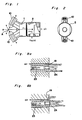
- Fig. 1 and 2 illustrate general aspects of a nozzle assembly in accordance with the invention.
- the nozzle assembly consists generally of a nozzle body (1) and an adapter (2) for air and water supply which is connected to the nozzle body 1.
- the nozzle body 1 has a plurality of nozzle heads (10) arranged in equi-spaced relation around its center, that is, the longitudinal axis (X-X) thereof.
- the number of nozzle heads (10) is not particularly limited.
- the nozzle body (1) has two nozzle heads. That is, the nozzle assembly has a two-head nozzle construction.
- Fig. 3b is an enlarged sectional view of the nozzle body (1) shown in Figs. 1 and 2.
- each nozzle head (10) of the nozzle body 1 has an air introduction path (17) for introducing compressed air thereinto, and a liquid introduction path 16 for introducing liquid, such as water or disinfectant solution, according to the purpose for which the atomizer is to be employed.
- the air introduction path (17) and the liquid introduction path (16) are respectively connected at one end to a compressed air introduction path and a liquid introduction path, both formed in the adapter 2.
- Each nozzle head (10) has a mounting hole (14) in which a nozzle tip (11) is housed or mounted. As shown, the nozzle tip (11) is housed in the mounting hole (14) at the front end side thereof, and is fixed by a plug (12) housed in the hole (14) at the rear end side thereof.
- Individual nozzle heads (10) and individual nozzle tips (11) housed therein are arranged so that the respective longitudinal axes (Y-Y) of the nozzle tips (11) converge at one particular point (A) on aforesaid longitudinal axis (X-X).
- the angle ( ⁇ ) at which a pair of longitudinal axes (Y-Y), (Y-Y) intersect each other is preferably set at 70°-160°.
- the distance between a pair of nozzle orifices is generally preferably set at 3-15 mm.
- each nozzle head (10) has a generally cylindrical configuration, and its front end portion includes a forwardly tapered portion (22) and a discharge port (19) having a smaller diameter cylindrical configuration and contiguous with the tapered portion (22).
- Each nozzle tip (11) consists generally of a large diameter base portion (25) and a small diameter front portion (26).
- the liquid passage hole (23) of the nozzle tip (11) extends along the longitudinal axis (Y-Y) of the nozzle tip (11) and has a front end opening (24) which is open centrally in the front end (33).
- This front end opening (24) may have a straight configuration as shown in Fig. 3b, or may have a slightly divergent configuration as shown in Fig. 3a.
- the large diameter base portion (25) of each nozzle tip (11) has a circumferential groove or communicating groove (30) formed on its outer periphery, and also has a communicating hole (27) which extends between the communicating groove (30) and the space in the tapered portion (22) of the mounting hole (14).
- the air introduction hole (17) is open to the communicating groove (30) so as to be in communication therewith. Accordingly, the compressed air supplied through the air introduction hole (17) is allowed to pass along an air discharge path (18) defined adjacent the outer periphery of the small diameter front portion (26), that is, through the tapered portion (22) and the discharge port, via said communicating groove (30) and said communicating hole (27), until it is jetted out.
- the small diameter front portion of the nozzle tip (11) extends in the discharge port (19) to form a throat portion (21) relative to the tapered portion (22), while the outer periphery of the small diameter front portion (26) of the nozzle tip (11) is forwardly tapered at the front end thereof so that the front end of the discharge port (19) is enlarged to form an enlarged portion (32). Therefore, the velocity of the compressed air to be jetted out reaches a sonic velocity level by causing the compressed air being caused to pass through the throat portion (21), and when the air reaches the enlarged portion (32) of the discharge port (19), negative pressure is developed.
- the liquid introduction path (16) is open into the communicating groove (28).
- the plug (12) has a center hole (15) in the center thereof at the front end side, and a communicating hole (29) which extends between the center hole (15) and the communicating groove (28). Accordingly, the liquid supplied into the liquid introduction path (16) is guided into the liquid passage hole (23) of the nozzle tip (11) after passing through the communicating groove (28), communicating hole (29), and center hole (15) in that order.
- Jet streams of a gas-liquid mixture discharged from the individual nozzle heads impinge against each other atone point (A) on the longitudinal axis (X-X), whereby a process of mutual shearing is repeated and simultaneously a supersonic wave of 20,000-40,000 Hz is generated, with the result of the droplets being reduced to finer particles.
- a supersonic wave of 20,000-40,000 Hz is generated, with the result of the droplets being reduced to finer particles.
- Nozzle tips each having a front end diameter of 1.3 mm and a liquid passage hole diameter of 0.4 mm, were mounted to a double head jet nozzle body (1) having a pair of discharge ports (an inter- discharge port distance: 8 mm, an intersecting angle (a): 120°), in such away that the front end of each nozzle tip (11) projected forward 0.3 mm from the corresponding discharge port (19) of the nozzle body (1) and that the throat portion (21) between the nozzle body (1) and the nozzle tip (11) had a sectional area of 0.5 mm 2 for allowing the passage of compressed air.
- the angle of taper (a) at the front tapered portion of the nozzle tip was varied in order to find out the relationship between the angle of taper (a) and maximal particle diameter (Fig.
- the maximal particle diameter was more than 50 microns (with mean particle diameter of more than about 10 microns) if the angle of front end taper (a) was less than 16° or in excess of 24°, and with such conditions (maximal particle diameter of not more than 50 microns) an ultrafine mist was accordingly not produced.
- the angle of taper (a) was in the vicinity of 20°, the maximal particle diameter was reduced to a minimum, say, about 30 11 m (with mean particle diameter of 8 microns).
- the angle of taper (a) was within the range of 16°-24°, the conditions for producing an ultrafine mist were satisfied.
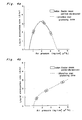
- Fig. 6 shows by way of example, the relationship between liquid atomization rate and air consumption when the taper angle (a) is set at 18°.
- atomization starts under an air pressure (Pa) of 100 kPa (1 kg/cm 2 ), and the liquid atomization rate continues to increase notably in relation to the rate of air consumption until an air pressure of 200 kPa (2 kg/cm 2 ) is reached.
- Pa air pressure
- 200 kPa 2 kg/cm 2
- the rate of air consumption tends to increase in proportion to the rise in air pressure.
- the air pressure is between 100 kPa (1 kg/cm 2 ) and 200 kPa (2 kg/cm 2 )
- the air pressure is greater than 250 kPa (2.5 kg/ cm 2 )
- a negative pressure corresponding to the liquid atomization rate results, so that the maximal diameter of liquid particles after impingement is not more than some 35 microns, a perfect ultrafine mist thus being realized.
- Fig. 4b shows the data of Fig. 6 in terms of the relation between air pressure and atomization rate.
- An ultrafine mist is produced when the pressure of compressed air is more than 250 kPa (2.5 kg/cm 2 ), the Sauter mean particle diameter being 10 microns.
- the mean particle diameter is 12 microns which is slightly coarser. That is, even at on/off stages of nozzle operation, no coarse particle mist is produced, and there is little or no possibility of the mist creating wettness on a floor and any other circumjacent surface.
- the present inventor conducted a second experiment. Attention was paid to the fact that the amount of projection (6) from the nozzle body (1) of the nozzle tip (11) at the front end thereof is another factor which determines the magnitude of a negative pressure produced as a result of compressed air passage. In this experiment, the amount of such projection was varied. It was found that where the amount of projection was within the range of 0.3-0.8 mm, atomization could be effected most steadily.
- the experiment conditions applied were basically the same as those in Experiment 1. In this case, however, the angle of taper at the front end of the nozzle tip (11) was set at 189, and the amount of projection (6) was varied in several increments.
- the pressure of compressed air was first set at 300 kPa (3.0 kg/ cm 2 ), and the amount of projection of the nozzle tip front end was increased sequentially from zero to 0.3 mm.
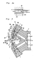
- Fig. 8a shows the condition of gas/ liquid flow when the amount of projection was zero
- Fig. 8b shows the condition of gas/liquid flow when the amount of projection was 0.3 mm.
- a negative pressure is produced as compressed air is jetted out from the discharge port (19) at a supersonic velocity, and simultaneously upon liquid drops being sucked from the front end opening (24) of the liquid passage (24), the liquid is first drawn into the discharge port (19) and then jetted out in conjunction with compressed air.
- the amount of projection is set at about 0.3 mm as shown in Fig. 8b, the effect of a negative pressure, if any, is insignificant and drops of liquid sucked from the liquid passage hole (23) do not spread except on the front end (33) of the nozzle tip; therefore, if such impurity deposition does occur at all, it only affects the tip front end (33) and, it is very easy to remove such deposit.
- Fig. 9b shows the results obtained when the nozzle in Fig. 8b was used. It can be clearly seen that the rate of atomization corresponds generally to the atomization rate setting of 2.0 I/hr.
- the amount of projection at the front end of the nozzle tip be set at more than 0.3 mm, but with the increase in the amount of such projection, particle diameters in a mist tend to become larger. In order to obtain an ultrafine mist, there is a certain limitation on the amount of such projection.
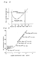
- Fig. 10 shows, where the quantity of projection is within the range of 0.3 mm-0.8 mm, the maximal particle diameter is 35 microns to less than 50 microns, necessary conditions for producing an ultrafine mist being fully met. However, if the projection is in excess of 0.8 mm, the maximum particle diameter is more than 50 microns, said conditions not being satisfied.
- an optimum range of nozzle tip front-end projection lengths is from 0.3 to 0.8 mm.
- the prior-art nozzle arrangement shown in Fig. 12 is subject to a problem in which a temperature drop may occur as a result of compressed air expansion in the discharge port (19), resulting in possibilities of the liquid drops freezing at the discharge port. Experiments were made in order to find how well this problem could be solved by this invention. The results were found satisfactory.
- the prior-art nozzle in Fig. 12 and the nozzle employed in Experiment 2 were both employed, and droplet freeze initiation temperatures were compared between the two nozzles while varying compressed air temperatures.
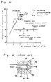
- the results are shown in Fig. 11.
- the air pressure is more than some 300 kPa (3 kg/ cm 2 )
- freezing starts at some 17°C with the prior-art nozzle
- freezing starts at about 8°C in the embodiment of the invention.
- the compressed air freezing temperature observed with the nozzle of the invention is about 9°C lower than that observed with the prior-art nozzle. Therefore, the nozzle in accordance with the invention is advantageous in that no preheating of compressed air is required in a normal range of uses.
Description
- The present invention relates to an atomizer nozzle assembly according to the preamble part of
claim 1. - Atomizers are employed in various fields for various purposes, such as humidifying, cooling, dust controlling, disinfectant solution spraying, and fuel oil atomizing. Generally, it is desirable that any mist produced by means of such a device should be an ultrafine mist. The reason is that if component particles of the mist are coarse, the surfaces of circumjacent objects will get wet in a given period of time when, for example, the atomizer is employed for humidifying purposes; and if the atomizer is employed for the purpose of disinfectant solution spraying, the circumjacent objects will get wet resulting in stains being left thereon.
- The present inventor, after his series of studies on such a problem, found that for an ultrafine mist to be realized its component liquid particles must not have a maximum particle diameter greater than 50 pm and have a Sauter mean diameter greater than 10 pm. On the basis of such a finding, the present inventor has already proposed various ultrafine mist producing atomizers (Japanese Published Unexamined PatentApplica- tion Nos. 54-111117, 55―49162 corresponding to US-A-4 284 239, and 57-42362).
- These are two types of nozzle assemblies, one or the other of which is employed in the ultrafine mist producing atomizers proposed by the present inventor. One type involves passing compressed air through a passage outside the nozzle tip, which may be called the outer air-passage type (Japanese Published Unexamined Patent Application Nos. 55―49162 and 57-42362). The other type involves passing compressed air through a passage defined within the nozzle tip, which may be called the inner air-passage type (Japanese Published Unexamined Patent Application No. 54-111117). From the standpoint of preventing the diffusion of a jet stream of a gas liquid mixture from the nozzle orifice, it is generally believed that nozzles of the outer air-passage type are preferable.
- As an illustration of a nozzle according to the preamble part of
claim 1 of the outer air-passage type, the general arrangement of the nozzle in the ultrafine mist producing atomizer disclosed in said US―A―4 284 239 is described below by way of example. - The basic arrangement of this nozzle is generally identical with that shown in Figs. 1 and 2, on which one embodiment of the present invention is based. That is, a nozzle body has a plurality of nozzle heads arranged in an equi-spaced relation around the longitudinal axis thereof, each of the nozzle heads having a mounting hole in which a nozzle tip is mounted. Each nozzle tip, as can be seen from Fig. 12 (in which a part of a nozzle is shown), has a
liquid passage hole 5a, while anair jet passage 5e is defined in amounting hole 5b between anozzle body 5c and the outer periphery of anozzle tip 5d. Individual mounting holes and individual nozzle tips are so arranged that the respective longitudinal axes of the nozzle tips converge at one point on the longitudinal axis of the nozzle body, whereby as currents of compressed air are caused to jet out toward said one point on the longitudinal axis of the nozzle body passing, through the air jet passages, the currents suck liquid thereinto through the respectivefront end openings 5f of the liquid passage holes to form jet streams of a gas-liquid mixture and the jet streams impinge agaisnt one another at said one point on said longitudinal axis, thereby producing an ultrafine mist of liquid. - With respect to the above-described prior art nozzle arrangement, it must be noted that, as Fig. 12 shows, the
front end openings 5f of theliquid passage hole 5a defined in eachnozzle tip 5e are open at sides of thefront end 5g of the tip and not on thefront end 5g itself; that the angle of taper of a front end taperedportion 5h of thenozzle tip 5d is about 7°-22°; and that the front end of thenozzle tip 5d projects little, if any, from thenozzle body 5c (the amount of such projection being in the order of 0.2 mmm at most). - The relationship between compressed air pressure and liquid atomization rate for the prior art nozzle arrangement is shown in Fig. 4a (conditions in Fig. 4 are: liquid pressure = 0; liquid suction height = 100 mm). It can be seen that there is no proportional relationship between compressed-air pressure and liquid atomization rate. In Fig. 4a, the mean particle diameter (referred to as Saufer mean particle diameter) in the mist is about 50 microns - about 10 microns in a low pressure zone ranging from an initial air pressure at which atomization starts to a pressure level of about 300 kPa (3 kg/cm) with no ultrafine mist being available realized. An ultrafine mist having a mean particle diameter of less than about 10 microns is produced only in a high pressure zone in which the air pressure is in excess of about 300 kPa (3 kg/cm2). However, as the air pressure becomes higher, the mean particle diameter becomes smaller, and as shown in the Fig. 4a, atomization is terminated when an air pressure of more than 400 kPa (4 kg/cm2) is reached. With the prior art arrangement, therefore, one problem is that at on/off control stages for compressed air supply, a mist having a relatively coarse particle size is produced, so that the floor and circumjacent surfaces get wet. Another problem is that when only a small amount of ultrafine mist is required, it is necessary to increase the air pressure, which means that a disproportionally greater amount of air consumption for the liquid atomization is required which is extremely uneconomical. A further problem is that the diameter of particles in the mist varies with changes in air pressure, or in other words, mist having a constant particle diameter cannot be produced.
- These problems are considered to be attributable to the front end structure of the nozzle and, more particularly, to the fact that a negative pressure develops thereat as a compressed air current passes at a supersonic velocity through the nozzle orifice.
- From GB-A-2 162 769 a nozzle is known which has a tapered portion to lead secondar air to the nozzle tip which amplifies the flow and blankets and reduces the noise generated by the primary air discharged from the nozzle. This nozzle assembly is used for coating a target with liquid and it is especially suited for great working distances of more than 1,2 m. Furthermore, it is stated in this document that the tapered nozzle is not useful for producing ultrafine mist.
- It is, therefore, the object of the present invention to provide an atomizer nozzle assembly having an improved front end structure which is likely to cause a negative pressure and a satisfactory pattern of compressed air flow which enables a substantially ultrafine mist to be produced at a point of time when atomization is initiated under an initial pressure of compressed air, and which enables an ultrafine mist to be produced when a slightly higher level of air pressure is reached, at a flow rate generally proportional to the pressure rise.
- This object is achieved according to the present invention by an atomizer nozzle assembly having the features given in
claim 1. - Such an arrangement is based on findings derived from certain experiments which will be described hereinafter. With such an arrangement it is possible to produce a substantially ultrafine mist at the start of the atomizing operation and also to produce an ultrafine mist having a constant particle diameter during rise in the initial pressure of compressed air immediately following the start of atomization.
- Therefore, according to the invention, there will be no generation of any coarse particle mist at on/ off stages for compressed air jetting, and thus there is no possibility of the mist causing the floor and other circumjacent surfaces to become wet. Furthermore, with a rise in the pressure of compressed air, an ultrafine mist having a generally uniform particle diameter can be produced at a rate proportional to the pressure rise.
- In the foregoing arrangement, it is desirable that the front end of each nozzle tip should project forward from the front end of the corresponding nozzle tip, and that the length of such projection be set within the range of 0.3-0.8 mm. With such an arrangement, it is possible to ensure stable atomization. That is, by arranging the front end of each nozzle tip so that it projects forward more than 0.3 mm, it is possible to produce a steady jet stream of gas-liquid mixture, because droplets of liquid sucked outward from the liquid passage hole becomes less inclined to be attracted toward an enlarged portion defined between the front tapered portion of the nozzle tip and the interior of the nozzle head, that is, in a back flow direction, while on the other hand by limiting the length of the nozzle tip projection to not more than 0.8 mm it is possible to control the maximal diameter of liquid particles in a mist to not more than 50 microns, the permissible maximum particle diameter for realizing an ultrafine mist.
- It is to be noted in this conjunction that if the front end opening of the liquid passage hole in the nozzle tip is reverse tapered, it is possible to obtain an ultrafine mist having a more uniform particle diameter.
- This and other objects and features of the present invention will become apparent from the following description taken in conjunction with the preferred embodiment thereof, with reference to the accompanying drawings, in which:
- Figs. 1 and 2 are, respectively, a side view and a right end view, both showing an atomizer nozzle assembly in accordance with the invention;
- Fig. 3b is an enlarged longitudinal section view showing the nozzle in Figs. 1 and 2;
- Fig. 3a is a fragmentary sectional view showing a modified form of the nozzle in Fig. 3b;
- Fig. 4a is a graphic representation showing the relationship between air pressure (abscissa) and liquid atomization rate (ordinate) in the prior-art nozzle shown in Fig. 12;
- Fig. 4b is a graph showing the relationship between air pressure (abscissa) and liquid atomization rate (ordinate) on the basis of the results of experiments conducted by employing the nozzle of the present invention;
- Fig. 5 is a graph showing the relationship between angle of taper (a) at the nozzle tip front end (abscissa) and maximal liquid drop particle diameter (ordinate) on the basis of the results of experiments conducted by employing the nozzle of the invention;
- Fig. 6 is a graph showing the relationship between the liquid atomization rate (abscissa) and air consumption (ordinate) on the basis of the results of experiments conducted by employing the nozzle of the invention;
- Fig. 7a is a graph showing the relationship between the particle diameter (abscissa) and number of particles (ordinate) when one of the discharge ports in the nozzle assembly according to the invention was closed so that the nozzle assembly was employed as a single-head nozzle;
- Fig. 7b is a graph showing the relationship between particle diameter (abscissa) and number of particles (ordinate) when the double head nozzle according to the invention was employed as such;
- Fig. 8a is an explanatory view showing the condition of gas-liquid flow when the front end of the nozzle tip projects verylittle from the nozzle body;
- Fig. 8b is an explanatory view showing the condition of gas-liquid flow when the front end of the nozzle tip projects forward 0.3 mm from the nozzle body;
- Fig. 9a is a graph showing the relationship between liquid atomization rate (abscissa) and degree of angle (ordinate) according to Fig. 8a;
- Fig. 9b is a graph showing the relationship between liquid atomization rate (abscissa) and degree of angle (ordinate) according to Fig. 8b;
- Fig. 10 is a graph showing the relationship between the amount of nozzle tip projection (abscissa) and maximal particle diameter (ordinate);
- Fig. 11 is a graph showing the relationship between air pressure (abscissa) and compressed air temperature (ordinate), and also showing liquid droplet freezing temperatures; and
- Fig. 12 is a fragmentary sectional view showing a prior-art nozzle, as previously described.
- One preferrerd embodiment of the present invention will now be described in further detail in conjunction with experimental examples.
- Fig. 1 and 2 illustrate general aspects of a nozzle assembly in accordance with the invention. The nozzle assembly consists generally of a nozzle body (1) and an adapter (2) for air and water supply which is connected to the
nozzle body 1. Thenozzle body 1 has a plurality of nozzle heads (10) arranged in equi-spaced relation around its center, that is, the longitudinal axis (X-X) thereof. - The number of nozzle heads (10) is not particularly limited. In the present embodiment, the nozzle body (1) has two nozzle heads. That is, the nozzle assembly has a two-head nozzle construction.
- Fig. 3b is an enlarged sectional view of the nozzle body (1) shown in Figs. 1 and 2. As shown, each nozzle head (10) of the
nozzle body 1 has an air introduction path (17) for introducing compressed air thereinto, and aliquid introduction path 16 for introducing liquid, such as water or disinfectant solution, according to the purpose for which the atomizer is to be employed. The air introduction path (17) and the liquid introduction path (16) are respectively connected at one end to a compressed air introduction path and a liquid introduction path, both formed in theadapter 2. - Each nozzle head (10) has a mounting hole (14) in which a nozzle tip (11) is housed or mounted. As shown, the nozzle tip (11) is housed in the mounting hole (14) at the front end side thereof, and is fixed by a plug (12) housed in the hole (14) at the rear end side thereof.
- Individual nozzle heads (10) and individual nozzle tips (11) housed therein are arranged so that the respective longitudinal axes (Y-Y) of the nozzle tips (11) converge at one particular point (A) on aforesaid longitudinal axis (X-X). Generally, the angle (β) at which a pair of longitudinal axes (Y-Y), (Y-Y) intersect each other is preferably set at 70°-160°. The distance between a pair of nozzle orifices is generally preferably set at 3-15 mm.
- The mounting hole (14) in each nozzle head (10) has a generally cylindrical configuration, and its front end portion includes a forwardly tapered portion (22) and a discharge port (19) having a smaller diameter cylindrical configuration and contiguous with the tapered portion (22).
- Each nozzle tip (11) consists generally of a large diameter base portion (25) and a small diameter front portion (26). The liquid passage hole (23) of the nozzle tip (11) extends along the longitudinal axis (Y-Y) of the nozzle tip (11) and has a front end opening (24) which is open centrally in the front end (33). This front end opening (24) may have a straight configuration as shown in Fig. 3b, or may have a slightly divergent configuration as shown in Fig. 3a. The large diameter base portion (25) is in contact with the cylindrical interior of the
nozzle head 10 defining the mounting hole (14), while the small diameter front portion (26) projects slightly outward passing through the tapered portion (22) of the mounting hole (14) and then through the discharge port (19) (the length of projection = 5). The large diameter base portion (25) of each nozzle tip (11) has a circumferential groove or communicating groove (30) formed on its outer periphery, and also has a communicating hole (27) which extends between the communicating groove (30) and the space in the tapered portion (22) of the mounting hole (14). The air introduction hole (17) is open to the communicating groove (30) so as to be in communication therewith. Accordingly, the compressed air supplied through the air introduction hole (17) is allowed to pass along an air discharge path (18) defined adjacent the outer periphery of the small diameter front portion (26), that is, through the tapered portion (22) and the discharge port, via said communicating groove (30) and said communicating hole (27), until it is jetted out. The small diameter front portion of the nozzle tip (11) extends in the discharge port (19) to form a throat portion (21) relative to the tapered portion (22), while the outer periphery of the small diameter front portion (26) of the nozzle tip (11) is forwardly tapered at the front end thereof so that the front end of the discharge port (19) is enlarged to form an enlarged portion (32). Therefore, the velocity of the compressed air to be jetted out reaches a sonic velocity level by causing the compressed air being caused to pass through the throat portion (21), and when the air reaches the enlarged portion (32) of the discharge port (19), negative pressure is developed. - On the outer periphery of the plug (12) are mounted a pair of 0-
rings rings - Now, if the operation of the device is begun by supplying liquid (liquid pressure = 0) and compressed air to the nozzle assembly of the above-described construction, the compressed air sucks liquid droplets thereinto from the front end opening (24) of the nozzle tip (11) as it is jetted out from the discharge port (19), so that a jet stream of a gas-liquid mixture is realized. At this time, droplets of liquid are sheared by the compressed air into fine particles. Jet streams of a gas-liquid mixture discharged from the individual nozzle heads impinge against each other atone point (A) on the longitudinal axis (X-X), whereby a process of mutual shearing is repeated and simultaneously a supersonic wave of 20,000-40,000 Hz is generated, with the result of the droplets being reduced to finer particles. Thus, an ultrafine mist composed of microfine particles is released forward.
- With careful attention directed to the fact that in the nozzle assembly having the above-described construction, the angle of taper (a) at the front end portion of the nozzle top (11) is a factor having an important bearing on the flow pattern of compressed air and the magnitude of the resulting negative pressure, the present inventor conducted experiments with a variety of changes in the angle of taper (a) and found out several facts of great interest. The experiments are explained in detail hereinbelow.
- Nozzle tips, each having a front end diameter of 1.3 mm and a liquid passage hole diameter of 0.4 mm, were mounted to a double head jet nozzle body (1) having a pair of discharge ports (an inter- discharge port distance: 8 mm, an intersecting angle (a): 120°), in such away that the front end of each nozzle tip (11) projected forward 0.3 mm from the corresponding discharge port (19) of the nozzle body (1) and that the throat portion (21) between the nozzle body (1) and the nozzle tip (11) had a sectional area of 0.5 mm2 for allowing the passage of compressed air. The angle of taper (a) at the front tapered portion of the nozzle tip was varied in order to find out the relationship between the angle of taper (a) and maximal particle diameter (Fig. 5), the relationship between air pressure and liquid atomization rate (Fig. 4b), the relationship between liquid atomization rate and air comsumption (Fig. 6), and particle diameters in mists produced (Figs. 7a and 7b). The liquid pressure was set at 0, and the height of liquid suction at 100 mm.
- As can be seen from Fig. 5, under the air pressure condition of 300 kPa (3 kg/cm2), the maximal particle diameter was more than 50 microns (with mean particle diameter of more than about 10 microns) if the angle of front end taper (a) was less than 16° or in excess of 24°, and with such conditions (maximal particle diameter of not more than 50 microns) an ultrafine mist was accordingly not produced. When the angle of taper (a) was in the vicinity of 20°, the maximal particle diameter was reduced to a minimum, say, about 30 11m (with mean particle diameter of 8 microns). When the angle of taper (a) was within the range of 16°-24°, the conditions for producing an ultrafine mist were satisfied. This can be explained by the fact that, as Fig. 5 shows, when the angle of taper was in the vicinity of 20°, drops of liquid sucked into a negative pressure were first diverged, but were subsequently caused to impinge upon one another in a well contracted condition under currents of air discharged at a supersonic velocity. That is, if the taper angle (a) was excessively small, currents of air discharged were diverged under the influence of the circumjacent air resistance, and accordingly the jet streams were also diverged and slowed down, so that drops of liquid becane coarse. If the taper angle (a) was excessively large, compressed air was separated without being allowed to run along the tapered portion, and therefore jet streams were not well contracted. Thus, the density of impingement energy was substantially reduced with the result of liquid drops becoming coarse.
- On the basis of the above-described results, it can be said that if the angle of taper (a) at the front end of the nozzle tip is set within the range of 16°-24°, it is possible to obtain an ultrafine mist with a maximal particle diameter of not more than 50 microns. The provision of a liquid passage hole in the nozzle tip at the front end side thereof facilitates an effect in which the higher the pressure of compressed air, the larger is the negative pressure in the liquid passage hole. Thus, it is possible to increase the liquid atomization rate in proportion to the rise in the air pressure. The present invention is based on these experimental results.
- Fig. 6 shows by way of example, the relationship between liquid atomization rate and air consumption when the taper angle (a) is set at 18°. In this case, atomization starts under an air pressure (Pa) of 100 kPa (1 kg/cm2), and the liquid atomization rate continues to increase notably in relation to the rate of air consumption until an air pressure of 200 kPa (2 kg/cm2) is reached. When air pressure is increased to a level of more than 200 kPa (2 kg/cm2), the rate of air consumption tends to increase in proportion to the rise in air pressure. Where the air pressure is between 100 kPa (1 kg/cm2) and 200 kPa (2 kg/cm2), there is not sufficient negative pressure to provide any sufficient shearing action of sucked liquid droplets; therefore, the liquid drops are rather coarse and even after their impingement, the maximal particle diameter is in the vicinity of 60 microns, a value somewhat larger than the maximal particle size for realizing an ultrafine mist. However, when the air pressure is greater than 250 kPa (2.5 kg/ cm2), a negative pressure corresponding to the liquid atomization rate results, so that the maximal diameter of liquid particles after impingement is not more than some 35 microns, a perfect ultrafine mist thus being realized.
- Fig. 4b shows the data of Fig. 6 in terms of the relation between air pressure and atomization rate. An ultrafine mist is produced when the pressure of compressed air is more than 250 kPa (2.5 kg/cm2), the Sauter mean particle diameter being 10 microns. When the pressure is less than 250 kPa (2.5 kg/cm2), the mean particle diameter is 12 microns which is slightly coarser. That is, even at on/off stages of nozzle operation, no coarse particle mist is produced, and there is little or no possibility of the mist creating wettness on a floor and any other circumjacent surface.
- In the above-described experiment, jet streams of a gas-liquid mixture were jetted out simultaneously from a pair of discharge ports so that they were impinged against each other. In order to further clarify the fact that particle diameters of the mist produced in such a case were very fine and uniform, the above results were compared with those obtained when one of the discharge ports were sealed and jetting was effected from the other discharge port only. Fig. 7a shows results of atomizing operation with a single head nozzle, and fig. 7b shows results of operation with a double head nozzle. In both cases, examination was made under an air pressure of 300 kPa (3 kg/ cm2). With the single head nozzle, coarse particles having a maximum particle diameter of more than 90 microns were produced, whereas in the case with the double head nozzle, the maximum particle diameter was in the order of 35 microns at most. In the latter case, more than one half of the particles produced had a particle diameter of several microns and some 95% of the particles produced had a particle diameter of ten and odd microns, the particles as a whole being very fine and uniform.
- In addition to
Experiment 1, the present inventor conducted a second experiment. Attention was paid to the fact that the amount of projection (6) from the nozzle body (1) of the nozzle tip (11) at the front end thereof is another factor which determines the magnitude of a negative pressure produced as a result of compressed air passage. In this experiment, the amount of such projection was varied. It was found that where the amount of projection was within the range of 0.3-0.8 mm, atomization could be effected most steadily. - The experiment conditions applied were basically the same as those in
Experiment 1. In this case, however, the angle of taper at the front end of the nozzle tip (11) was set at 189, and the amount of projection (6) was varied in several increments. - In the
above experiment 2, the pressure of compressed air was first set at 300 kPa (3.0 kg/ cm2), and the amount of projection of the nozzle tip front end was increased sequentially from zero to 0.3 mm. Fig. 8a shows the condition of gas/ liquid flow when the amount of projection was zero, and Fig. 8b shows the condition of gas/liquid flow when the amount of projection was 0.3 mm. As is apparent from Fig. 8a, when the projection amount was zero, a negative pressure is produced as compressed air is jetted out from the discharge port (19) at a supersonic velocity, and simultaneously upon liquid drops being sucked from the front end opening (24) of the liquid passage (24), the liquid is first drawn into the discharge port (19) and then jetted out in conjunction with compressed air. This phenomenon dimishes gradually as the projection amount is increased, and almost ceases to exist when the amount of projection is increased to about 0.3 mm. If the phenomenon shown in Fig. 8a develops, a serious problem arises which may adversely affect the stability of atomization. That is, if such phenomenon develops, impurities contained in the liquid, such as silica, silicon, and magnesium, deposit on the sides of the nozzle tip over time, with the result that the desired atomization rate relative to the predetermined pressure of compressed air cannot be maintained. Fig. 9a shows such unfavorable results. In this instance, while the atomization rate is at 2.0 I, it is apparent that actual rate of atomization is scattered on both the + side and the - side, with 2.0 as a border line. As deposition of such impurities increases, a problem of blinding of the discharge port (19) will develop. - If the amount of projection is set at about 0.3 mm as shown in Fig. 8b, the effect of a negative pressure, if any, is insignificant and drops of liquid sucked from the liquid passage hole (23) do not spread except on the front end (33) of the nozzle tip; therefore, if such impurity deposition does occur at all, it only affects the tip front end (33) and, it is very easy to remove such deposit.
- Therefore, the flow of liquid drops is stabilized so that a uniform atomization rate can be assured. Fig. 9b shows the results obtained when the nozzle in Fig. 8b was used. It can be clearly seen that the rate of atomization corresponds generally to the atomization rate setting of 2.0 I/hr.
- Hence, it is desirable that the amount of projection at the front end of the nozzle tip be set at more than 0.3 mm, but with the increase in the amount of such projection, particle diameters in a mist tend to become larger. In order to obtain an ultrafine mist, there is a certain limitation on the amount of such projection.
- In view of these facts, the relationship between the quantity of projection (6) at the front nozzle tip end and mist particle diameter was examined using the pressure of compressed air as a parameter. Fig. 10 shows the results thereof.
- As Fig. 10 shows, where the quantity of projection is within the range of 0.3 mm-0.8 mm, the maximal particle diameter is 35 microns to less than 50 microns, necessary conditions for producing an ultrafine mist being fully met. However, if the projection is in excess of 0.8 mm, the maximum particle diameter is more than 50 microns, said conditions not being satisfied.
- Therefore, an optimum range of nozzle tip front-end projection lengths is from 0.3 to 0.8 mm.
- The prior-art nozzle arrangement shown in Fig. 12 is subject to a problem in which a temperature drop may occur as a result of compressed air expansion in the discharge port (19), resulting in possibilities of the liquid drops freezing at the discharge port. Experiments were made in order to find how well this problem could be solved by this invention. The results were found satisfactory.
- In this experiment, the prior-art nozzle in Fig. 12 and the nozzle employed in Experiment 2 (with the nozzle tip projection set at 0.3 mm) were both employed, and droplet freeze initiation temperatures were compared between the two nozzles while varying compressed air temperatures. The results are shown in Fig. 11. As can be seen, if the air pressure is more than some 300 kPa (3 kg/ cm2), freezing starts at some 17°C with the prior-art nozzle, whereas freezing starts at about 8°C in the embodiment of the invention. In other words, the compressed air freezing temperature observed with the nozzle of the invention is about 9°C lower than that observed with the prior-art nozzle. Therefore, the nozzle in accordance with the invention is advantageous in that no preheating of compressed air is required in a normal range of uses.
Claims (2)
Applications Claiming Priority (2)
| Application Number | Priority Date | Filing Date | Title |
|---|---|---|---|
| JP61134173A JPS62289257A (en) | 1986-06-09 | 1986-06-09 | Hyperfine mist injection nozzle |
| JP134173/86 | 1986-06-09 |
Publications (2)
| Publication Number | Publication Date |
|---|---|
| EP0249186A1 EP0249186A1 (en) | 1987-12-16 |
| EP0249186B1 true EP0249186B1 (en) | 1991-01-23 |
Family
ID=15122149
Family Applications (1)
| Application Number | Title | Priority Date | Filing Date |
|---|---|---|---|
| EP87108288A Expired EP0249186B1 (en) | 1986-06-09 | 1987-06-09 | Atomizer nozzle assemble |
Country Status (4)
| Country | Link |
|---|---|
| US (1) | US4783008A (en) |
| EP (1) | EP0249186B1 (en) |
| JP (1) | JPS62289257A (en) |
| DE (1) | DE3767573D1 (en) |
Families Citing this family (65)
| Publication number | Priority date | Publication date | Assignee | Title |
|---|---|---|---|---|
| US4960244A (en) * | 1989-05-08 | 1990-10-02 | Schering Corporation | Atomizing nozzle assembly |
| AU8072491A (en) * | 1990-05-30 | 1991-12-31 | Weyerhaeuser Company | Applicator for directing coating materials at a substrate |
| EP0461930B1 (en) * | 1990-06-15 | 1995-09-13 | Merck & Co. Inc. | A crystallization method to improve crystal structure and size |
| JP2633753B2 (en) * | 1991-09-21 | 1997-07-23 | 株式会社いけうち | humidifier |
| JP3513162B2 (en) * | 1992-03-27 | 2004-03-31 | 東京瓦斯株式会社 | Nitrogen oxide removal method |
| JP3499576B2 (en) * | 1992-03-27 | 2004-02-23 | 東京瓦斯株式会社 | Method and apparatus for removing nitrogen oxides |
| JP3513163B2 (en) * | 1992-03-27 | 2004-03-31 | 東京瓦斯株式会社 | Method and apparatus for removing nitrogen oxides |
| ATE177613T1 (en) * | 1992-09-26 | 1999-04-15 | Chemo Sero Therapeut Res Inst | TISSUE ADHESIVE APPLICATOR |
| JPH08501982A (en) * | 1992-10-06 | 1996-03-05 | メルク エンド カンパニー インコーポレーテッド | Double injection crystallizer |
| US5387403A (en) * | 1993-06-15 | 1995-02-07 | H. Ikeuchi & Co., Ltd. | Automatic sterilizing apparatus |
| US6196525B1 (en) | 1996-05-13 | 2001-03-06 | Universidad De Sevilla | Device and method for fluid aeration via gas forced through a liquid within an orifice of a pressure chamber |
| US6792940B2 (en) | 1996-05-13 | 2004-09-21 | Universidad De Sevilla | Device and method for creating aerosols for drug delivery |
| US6595202B2 (en) | 1996-05-13 | 2003-07-22 | Universidad De Sevilla | Device and method for creating aerosols for drug delivery |
| US6386463B1 (en) | 1996-05-13 | 2002-05-14 | Universidad De Sevilla | Fuel injection nozzle and method of use |
| US6299145B1 (en) | 1996-05-13 | 2001-10-09 | Universidad De Sevilla | Device and method for fluid aeration via gas forced through a liquid within an orifice of a pressure chamber |
| US6405936B1 (en) | 1996-05-13 | 2002-06-18 | Universidad De Sevilla | Stabilized capillary microjet and devices and methods for producing same |
| US6187214B1 (en) | 1996-05-13 | 2001-02-13 | Universidad De Seville | Method and device for production of components for microfabrication |
| US6116516A (en) | 1996-05-13 | 2000-09-12 | Universidad De Sevilla | Stabilized capillary microjet and devices and methods for producing same |
| US6189803B1 (en) | 1996-05-13 | 2001-02-20 | University Of Seville | Fuel injection nozzle and method of use |
| ES2140998B1 (en) * | 1996-05-13 | 2000-10-16 | Univ Sevilla | LIQUID ATOMIZATION PROCEDURE. |
| CN1226960A (en) * | 1996-07-08 | 1999-08-25 | 康宁股份有限公司 | Gas-assisted atomizing device |
| AU728998B2 (en) * | 1996-07-08 | 2001-01-25 | Corning Incorporated | Rayleigh-breakup atomizing devices and methods of making rayleigh-breakup atomizing devices |
| CA2307295A1 (en) * | 1997-10-17 | 1999-04-29 | Keyspan Corporation | Colliding jet nozzle and method of manufacturing same |
| WO1999030831A1 (en) * | 1997-12-17 | 1999-06-24 | Universidad De Sevilla | Fuel injection nozzle and method of use |
| WO2000015117A1 (en) | 1998-09-17 | 2000-03-23 | Focal, Inc. | Self-cleaning fluid delivery device for medical applications |
| US6450189B1 (en) | 1998-11-13 | 2002-09-17 | Universidad De Sevilla | Method and device for production of components for microfabrication |
| GB9919693D0 (en) * | 1999-08-19 | 1999-10-20 | Rhone Poulenc Rorer Ltd | Process |
| US6892963B1 (en) * | 1999-09-10 | 2005-05-17 | Usbi Co | Portable convergent spray gun capable of being hand-held |
| FR2827528B1 (en) * | 2001-07-20 | 2004-07-09 | Oreal | DISTRIBUTION HEAD COMPRISING TWO NOZZLES |
| US6755359B2 (en) | 2002-09-12 | 2004-06-29 | The Boeing Company | Fluid mixing injector and method |
| US6802178B2 (en) * | 2002-09-12 | 2004-10-12 | The Boeing Company | Fluid injection and injection method |
| US6775987B2 (en) | 2002-09-12 | 2004-08-17 | The Boeing Company | Low-emission, staged-combustion power generation |
| US7217254B2 (en) | 2002-09-20 | 2007-05-15 | Genzyme Corporation | Multi-pressure biocompatible agent delivery device and method |
| NZ525880A (en) * | 2003-05-14 | 2005-11-25 | Methven Ltd | Method and apparatus for producing droplet spray |
| US6955063B2 (en) * | 2003-06-14 | 2005-10-18 | Nanomist Systems, Llc | Cooling of electronics and high density power dissipation systems by fine-mist flooding |
| JP2005296874A (en) * | 2004-04-14 | 2005-10-27 | Ikeuchi:Kk | Supermicromist spray nozzle |
| US20060147853A1 (en) * | 2005-01-06 | 2006-07-06 | Lipp Charles W | Feed nozzle assembly and burner apparatus for gas/liquid reactions |
| EP1731225A1 (en) * | 2005-06-06 | 2006-12-13 | H. Ikeuchi & Co., Ltd. | Ultra-fine spray nozzle with intersecting jets |
| US20060283985A1 (en) * | 2005-06-09 | 2006-12-21 | H. Ikeuchi & Co., Ltd. | Ultra-fine spray-jetting nozzle |
| US7219849B1 (en) * | 2005-12-13 | 2007-05-22 | Graves Spray Supply, Inc. | Liquid impingement nozzle with paired openings |
| JP4823675B2 (en) * | 2005-12-16 | 2011-11-24 | 花王株式会社 | Method for producing hydrogel particles, hydrogel particles produced thereby, and dispersion using the same |
| US8517693B2 (en) | 2005-12-23 | 2013-08-27 | Exxonmobil Upstream Research Company | Multi-compressor string with multiple variable speed fluid drives |
| FI118355B (en) * | 2006-02-16 | 2007-10-15 | Beneq Oy | Burner |
| GB0607667D0 (en) * | 2006-04-19 | 2006-05-31 | Delavan Ltd | Spray nozzle |
| BRPI0715966A2 (en) | 2006-08-28 | 2013-08-06 | Air Prod & Chem | apparatus, and method |
| US20080230053A1 (en) | 2006-09-15 | 2008-09-25 | Board Of Regents, The University Of Texas System | Pulse drug nebulization systems, formulations therefore, and methods of use |
| FI119223B (en) * | 2007-02-19 | 2008-09-15 | Marioff Corp Oy | Spray head, fire extinguishing apparatus and method |
| CN101264361B (en) * | 2007-03-14 | 2010-09-15 | 龚坚 | Nasal cavity atomizing and flushing dual-purpose nozzle and atomizing and flushing device |
| EP2195576B1 (en) | 2007-08-28 | 2019-03-27 | Air Products and Chemicals, Inc. | Apparatus and method for controlling the temperature of a cryogen |
| WO2011004783A1 (en) | 2009-07-08 | 2011-01-13 | 本田技研工業株式会社 | Particle image flow velocity measuring method, method for measuring particle image flow velocities in three-dimensional space, particle image flow velocity measuring device, and tracer particle generation device in particle image flow velocity measuring device |
| JP5312238B2 (en) * | 2009-07-08 | 2013-10-09 | 本田技研工業株式会社 | Tracer particle generator for particle image velocimetry |
| JP2011125769A (en) * | 2009-12-15 | 2011-06-30 | Meiji Kikai Seisakusho:Kk | Air spray gun |
| DE102010015063A1 (en) * | 2010-04-15 | 2011-10-20 | Marco Systemanalyse Und Entwicklung Gmbh | Method for generating water mist to reduce danger of methane gas explosion in mining construction, involves generating mist without addition of air under high pressure through nozzle and directing mist to baffle to atomize mist droplets |
| US8499764B2 (en) | 2010-05-26 | 2013-08-06 | The Invention Science Fund I, Llc | Portable apparatus for establishing an isolation field |
| GB201009644D0 (en) * | 2010-06-09 | 2010-07-21 | Astek Innovations Ltd | Improved dental nozzle |
| US9545184B2 (en) | 2010-08-27 | 2017-01-17 | Xiamen Solex High-Tech Industries Co., Ltd. | Rich air sprayer of sanitary ware |
| US9022999B2 (en) | 2012-05-02 | 2015-05-05 | Elwha, Llc | Fluid spraying apparatuses, and related systems and methods |
| US9101743B2 (en) | 2012-05-02 | 2015-08-11 | Elwha, Llc | Fluid spraying apparatuses, and related systems and methods |
| US10035154B2 (en) | 2015-06-08 | 2018-07-31 | Michael J. Hochbrueckner | Device, system, and method for atomizer nozzle assembly with adjustable impingement |
| US20180326321A1 (en) * | 2015-06-08 | 2018-11-15 | Michael J. Hochbrueckner | Device, system, and method for atomizer nozzle assembly |
| US10857507B2 (en) * | 2016-03-23 | 2020-12-08 | Alfa Laval Corporate Ab | Apparatus for dispersing particles in a liquid |
| US9950328B2 (en) * | 2016-03-23 | 2018-04-24 | Alfa Laval Corporate Ab | Apparatus for dispersing particles in a fluid |
| CN109201364B (en) * | 2018-09-13 | 2020-10-27 | 宁波工程学院 | Spraying device for improving spraying uniformity |
| EP3954467A1 (en) * | 2020-08-10 | 2022-02-16 | A. Raymond et Cie | Consumption optimized nozzle assembly |
| DE102021210032A1 (en) | 2021-09-10 | 2023-03-16 | Volkswagen Aktiengesellschaft | Combined cleaning nozzle, cleaning system and motor vehicle |
Family Cites Families (10)
| Publication number | Priority date | Publication date | Assignee | Title |
|---|---|---|---|---|
| FR368457A (en) * | 1900-01-01 | |||
| US1398397A (en) * | 1919-02-01 | 1921-11-29 | Parmly H Ryder | Oil-burner |
| US2325495A (en) * | 1940-01-12 | 1943-07-27 | Nat Airoil Burner Company Inc | Oil burner |
| US3093315A (en) * | 1959-03-23 | 1963-06-11 | Tachiki Kenkichi | Atomization apparatus |
| US3062454A (en) * | 1961-06-12 | 1962-11-06 | Eric H Cocks | Mist spray ring |
| US3219276A (en) * | 1962-10-16 | 1965-11-23 | Edward O Norris | Plural nozzles having intersecting spray and control therefor |
| JPS54111117A (en) * | 1978-02-17 | 1979-08-31 | Ikeuchi Kk | Method of and apparatus for atomizing liquid |
| JPS5549162A (en) * | 1978-10-03 | 1980-04-09 | Ikeuchi:Kk | Mist producting device |
| JPS5742362A (en) * | 1980-08-22 | 1982-03-09 | Ikeuchi:Kk | Atomized spray generator |
| US4555059A (en) * | 1984-08-06 | 1985-11-26 | Vortec Corporation | Flow-amplifying liquid-atomizing nozzle |
-
1986
- 1986-06-09 JP JP61134173A patent/JPS62289257A/en active Granted
-
1987
- 1987-06-09 US US07/060,086 patent/US4783008A/en not_active Expired - Lifetime
- 1987-06-09 EP EP87108288A patent/EP0249186B1/en not_active Expired
- 1987-06-09 DE DE8787108288T patent/DE3767573D1/en not_active Expired - Lifetime
Also Published As
| Publication number | Publication date |
|---|---|
| JPH049104B2 (en) | 1992-02-19 |
| US4783008A (en) | 1988-11-08 |
| JPS62289257A (en) | 1987-12-16 |
| EP0249186A1 (en) | 1987-12-16 |
| DE3767573D1 (en) | 1991-02-28 |
Similar Documents
| Publication | Publication Date | Title |
|---|---|---|
| EP0249186B1 (en) | Atomizer nozzle assemble | |
| EP0650766B1 (en) | Suction feed nozzle assembly for HVLP spray gun | |
| EP0705644A1 (en) | Internal mix air atomizing spray nozzle | |
| US4413784A (en) | Constant-output atomizer | |
| US5088648A (en) | Nozzle head for a paint spray gun | |
| EP0904842A2 (en) | Improved air assisted spray system | |
| US5687906A (en) | Atomization method and atomizer | |
| JP4017522B2 (en) | Aerosol generating apparatus and method | |
| US4232824A (en) | Method and apparatus for the pneumatic spraying of liquid products | |
| JPH06304501A (en) | Air addition type atomizing device suitable for coating | |
| JPS62204873A (en) | Spray nozzle | |
| EP1893305A2 (en) | High velocity low pressure emitter | |
| WO1993001893A1 (en) | Apparatus and method for applyling a stream of atomized fluid | |
| US4511087A (en) | Air mist nozzle apparatus | |
| JP2004216320A (en) | Spray nozzle | |
| CA1238071A (en) | Atomizer | |
| JP2000308839A (en) | Coating utensil | |
| US7389951B2 (en) | Misting device | |
| JPH05337405A (en) | Liquid atomizing device | |
| JPH08141448A (en) | Low pressure atomizing spray gun including mixing of inside and outside | |
| JPH07124502A (en) | Binary fluid nozzle | |
| RU2024324C1 (en) | Pneumoacoustic injector | |
| Dea | Constant-output atomizer | |
| JPH05208148A (en) | Ultrafine jet nozzle | |
| JPS635141B2 (en) |
Legal Events
| Date | Code | Title | Description |
|---|---|---|---|
| PUAI | Public reference made under article 153(3) epc to a published international application that has entered the european phase |
Free format text: ORIGINAL CODE: 0009012 |
|
| AK | Designated contracting states |
Kind code of ref document: A1 Designated state(s): DE GB IT |
|
| 17P | Request for examination filed |
Effective date: 19880304 |
|
| 17Q | First examination report despatched |
Effective date: 19880711 |
|
| GRAA | (expected) grant |
Free format text: ORIGINAL CODE: 0009210 |
|
| AK | Designated contracting states |
Kind code of ref document: B1 Designated state(s): DE GB IT |
|
| REF | Corresponds to: |
Ref document number: 3767573 Country of ref document: DE Date of ref document: 19910228 |
|
| ITF | It: translation for a ep patent filed |
Owner name: ST. DR. CAVATTONI ING. A. RAIMONDI |
|
| PLBE | No opposition filed within time limit |
Free format text: ORIGINAL CODE: 0009261 |
|
| STAA | Information on the status of an ep patent application or granted ep patent |
Free format text: STATUS: NO OPPOSITION FILED WITHIN TIME LIMIT |
|
| 26N | No opposition filed | ||
| REG | Reference to a national code |
Ref country code: GB Ref legal event code: IF02 |
|
| PGFP | Annual fee paid to national office [announced via postgrant information from national office to epo] |
Ref country code: GB Payment date: 20060620 Year of fee payment: 20 |
|
| PGFP | Annual fee paid to national office [announced via postgrant information from national office to epo] |
Ref country code: IT Payment date: 20060630 Year of fee payment: 20 |
|
| PGFP | Annual fee paid to national office [announced via postgrant information from national office to epo] |
Ref country code: DE Payment date: 20060822 Year of fee payment: 20 |
|
| REG | Reference to a national code |
Ref country code: GB Ref legal event code: PE20 |
|
| PG25 | Lapsed in a contracting state [announced via postgrant information from national office to epo] |
Ref country code: GB Free format text: LAPSE BECAUSE OF EXPIRATION OF PROTECTION Effective date: 20070608 |