JP2005296874A - Supermicromist spray nozzle - Google Patents
Supermicromist spray nozzle Download PDFInfo
- Publication number
- JP2005296874A JP2005296874A JP2004119566A JP2004119566A JP2005296874A JP 2005296874 A JP2005296874 A JP 2005296874A JP 2004119566 A JP2004119566 A JP 2004119566A JP 2004119566 A JP2004119566 A JP 2004119566A JP 2005296874 A JP2005296874 A JP 2005296874A
- Authority
- JP
- Japan
- Prior art keywords
- gas
- liquid
- passage
- nozzle
- gas passage
- Prior art date
- Legal status (The legal status is an assumption and is not a legal conclusion. Google has not performed a legal analysis and makes no representation as to the accuracy of the status listed.)
- Pending
Links
Images

Landscapes
- Nozzles (AREA)
Abstract
Description
本発明は超微霧噴射ノズルに関し、水、薬液、油等の液体を空気等の気体と混合噴霧して平均粒子径が数μmの超微粒子とし、手に触れても濡れがない乾いた状態の噴霧、所謂、ドライフォッグを発生させるための二流体用ノズルに関するものである。 The present invention relates to a super fine mist injection nozzle, which is a dry state in which a liquid such as water, a chemical solution, or oil is mixed and sprayed with a gas such as air to form ultrafine particles having an average particle size of several μm and does not wet even when touched by the hand. This is related to a two-fluid nozzle for generating a so-called dry fog.
ノズルから液体を噴射する際、平均粒子径を10μm以下、最大粒子径を50μm以下とすると、手で触っても濡れが感じられない噴霧、いわゆるドライフォッグとなる。該ドライフォッグは噴霧時に濡れを発生させないため、空調用のノズルに好適に用いられるとともに、他の用途にも広範囲で用いられている。 When the liquid is ejected from the nozzle, if the average particle size is 10 μm or less and the maximum particle size is 50 μm or less, spraying that does not feel wet even when touched by hand, so-called dry fog is formed. Since the dry fog does not cause wetting during spraying, it is suitably used for air-conditioning nozzles and is also widely used for other applications.
この種の超微霧噴射ノズルとして、本出願人は特開昭54−111117(特許文献1)、特公昭62−14343号(特許文献2)、特公平4−9104号(特許文献3)等の多数の特許を提供している。
前記特許文献で提案したノズルは、液体と気体との二流体ノズルで、ノズル本体よりV字状に分岐させた後に屈曲させて先端を互いに向き合わせたノズル収納部を設け、これらノズル収納部に夫々ノズルチップを搭載している。各ノズルチップの外周とノズル収納部との間に空気通路を設けると共に、ノズルチップの中心に液体通路を設け、ノズルチップの噴射部において、空気通路より噴射する圧搾空気によって液体通路の先端開口より液体を吸引し気液混合体として棒流を発生させている。一対のノズルチップは噴射部を向き合わせに配置していることにより、前記気液混合体が衝突して超微霧を発生させている。
As this type of ultra-fine mist injection nozzle, the present applicant has disclosed Japanese Patent Application Laid-Open No. 54-11111 (Patent Document 1), Japanese Patent Publication No. 62-14343 (Patent Document 2), Japanese Patent Publication No. 4-9104 (Patent Document 3), and the like. Offers numerous patents.
The nozzle proposed in the above-mentioned patent document is a two-fluid nozzle of liquid and gas, and is provided with a nozzle storage section that is bent after being branched into a V shape from the nozzle body and has its tips facing each other. Each has a nozzle tip. An air passage is provided between the outer periphery of each nozzle tip and the nozzle storage portion, and a liquid passage is provided at the center of the nozzle tip. The compressed air injected from the air passage at the nozzle tip injection portion is more than the opening of the liquid passage. A liquid is sucked to generate a stick flow as a gas-liquid mixture. Since the pair of nozzle tips are arranged so that the injection portions face each other, the gas-liquid mixture collides to generate a super fine mist.
前記構成の超微霧噴射ノズルは、対向配置するノズルチップ噴射部より気液混合体を噴射させて衝突混合させていることで、気体との混合で微粒化した液滴が更に衝突混合することでより微粒化され、前記1〜10μmの液滴となり、ドライフォッグとなる超微霧を発生させることができる。 The super fine mist injection nozzle having the above-described configuration causes the gas-liquid mixture to be injected from the nozzle tip injection unit arranged to collide and collide and mix, so that droplets atomized by mixing with gas further collide and mix. It is possible to generate a super fine mist that is further atomized and becomes droplets of 1 to 10 μm and becomes dry fog.
このように、前記ノズルは超微霧を発生させることができる点で優れているが、ノズルチップ先端の噴射部Aで目詰まりを発生しにくくする点およびノズルから発生する騒音を低下させる点等で改良の余地がある。
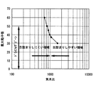
粒子径を小さくするには、圧搾空気量を多くして気水比が高くすることが好ましい。しかし、気水比(気体体積/液体体積)が高くなり、空気量が増加すると、空気および水に含まれている不純物が噴射口近傍で析出し、析出した不純物はノズルチップやノズル本体、特に空気通路の噴射口部分に付着しやすくなり、目詰まり発生の原因となる。本発明者の実験によると気水比が1000を超えると、目詰まりが発生し易くなっている。
As described above, the nozzle is excellent in that it can generate a super fine mist. However, it is difficult to cause clogging in the injection portion A at the tip of the nozzle tip, and noise generated from the nozzle is reduced. There is room for improvement.
In order to reduce the particle diameter, it is preferable to increase the compressed air amount to increase the air / water ratio. However, when the air / water ratio (gas volume / liquid volume) increases and the amount of air increases, impurities contained in the air and water are deposited in the vicinity of the injection port, It becomes easy to adhere to the injection port portion of the air passage, causing clogging. According to the experiment of the present inventor, when the air / water ratio exceeds 1000, clogging is likely to occur.
目詰まり防止対策として、気水比を下げて圧搾空気量を減少することが有効な対策となるが気水比を1000未満とすると、前記特許文献1のノズルでは粒子径が比較的大きくなり、超微霧化できない問題がある。図16は気水比と最大粒子径と目詰まり発生率とを対比するために本発明者が測定を行った結果を示すグラフを示す。該グラフより、気水比を1000以上とすると粒子径が減少するが、目詰まりが発生し易くなり、気水比が1000未満であると目詰まりは発生しにくくなるが粒子径が増大することが認められている。 As an anti-clogging measure, reducing the air / water ratio and reducing the amount of compressed air is an effective measure, but if the air / water ratio is less than 1000, the nozzle of Patent Document 1 has a relatively large particle size, There is a problem that can not be atomized. FIG. 16 is a graph showing the results of measurements made by the present inventor in order to compare the air / water ratio, the maximum particle diameter, and the occurrence rate of clogging. From the graph, when the air / water ratio is 1000 or more, the particle diameter decreases, but clogging is likely to occur, and when the air / water ratio is less than 1000, clogging is less likely to occur but the particle diameter increases. Is allowed.
また、水や空気に含まれる不純物の混入を防止することにより目詰まり発生を防止することも考えられるが、水に含まれるカルシウムやシリカが不純物となり、水や圧搾空気の供給管に付着しているシール剤や切削油等も不純物となる。水は純水器を付設して純水を利用すると不純物をある程度除去できるが、水中に溶解している前記カルシウムやシリカまで完全に除去することは困難である。また、埃等が多い環境条件下では空気中に異物が混入しやすく、エアーフィルタを通しても微小断面積となる空気通路の目詰まり発生原因となる異物まで完全に除去することは困難である。
このように、目詰まりの発生を有効に抑制、防止することは非常に困難で、目詰まりが発生するノズルをメンテナンスする必要があるため、作業効率が低下する問題がある。
It is also conceivable to prevent clogging by preventing the inclusion of impurities contained in water and air, but calcium and silica contained in water become impurities and adhere to the water and compressed air supply pipes. The sealing agent and cutting oil that are present also become impurities. Impurities can be removed to some extent by using pure water with a pure water device attached thereto, but it is difficult to completely remove calcium and silica dissolved in water. Further, under environmental conditions with a lot of dust and the like, foreign substances are likely to be mixed in the air, and it is difficult to completely remove even foreign substances that cause clogging of the air passage having a minute cross-sectional area through the air filter.
As described above, it is very difficult to effectively suppress and prevent the occurrence of clogging, and it is necessary to perform maintenance on the nozzle where clogging occurs.
また、粒子径を微粒化させるには気水比をあげて圧搾空気量を増加し、かつ、空気通路の断面積を小さくする必要があるが、空気通路の断面積を小さくすると、ノズルから発生する音が大きくなりやすく、静寂な環境下においてはノズルの発生音は騒音となる。さらに、気水比を上げるとコスト高になる問題もある。
本発明は前記問題に鑑みてなされたもので、液滴の平均粒子径が10μm以下、最大粒子径が50μm以下とする超微霧噴霧ノズルにおいて、主として目詰まりを発生を抑制し、かつ、気水比を低下させて、低音化、低コスト化を図ることを課題としている。 The present invention has been made in view of the above problems. In an ultrafine spray nozzle in which the average particle size of droplets is 10 μm or less and the maximum particle size is 50 μm or less, the occurrence of clogging is mainly suppressed, and The problem is to reduce the water ratio to achieve low sound and low cost.
前記課題を解決するため、本発明は、第1に、液体通路の外周側に仕切壁を介して気体通路を設け、噴射口に連通する気体通路は、前記仕切壁の噴射口側の外形を断面多角形状、長円状あるいは楕円状の異形とする一方、前記気体通路の外周面を断面円形として、該断面円形の外周面に前記仕切壁の異形の外面を複数箇所で当接させて前記噴射側の気体通路を周方向に複数の気体通路に分離させ、あるいは
前記仕切壁の外面を断面円形とする一方、前記気体通路の噴射口側の外周面を断面多角形状、長円状あるいは楕円状の異形として前記仕切壁の外周面を面に複数箇所で当接させ、前記噴射側の気体通路を周方向に複数の気体通路に分離させ、
前記液体通路から噴射する液体の外周に前記分離させた複数の気体通路の噴射口から噴射する気体を混合させて噴霧を発生させていることを特徴とする超微霧噴射ノズルを提供している。
In order to solve the above problems, the present invention firstly provides a gas passage through a partition wall on the outer peripheral side of the liquid passage, and the gas passage communicating with the injection port has an outer shape on the injection port side of the partition wall. While the outer surface of the gas passage is circular in cross section, the outer surface of the gas passage has a circular shape in cross section, and the outer surface of the partition wall is in contact with the outer surface of the partition wall at a plurality of locations. The gas passage on the injection side is divided into a plurality of gas passages in the circumferential direction, or the outer surface of the partition wall is circular in cross section, while the outer peripheral surface on the injection port side of the gas passage is polygonal in cross section, oval or oval The outer peripheral surface of the partition wall is abutted at a plurality of locations on the surface as a deformed shape, and the gas passage on the injection side is separated into a plurality of gas passages in the circumferential direction,
There is provided an ultra fine mist injection nozzle characterized in that spray is generated by mixing the gas injected from the outlets of the plurality of separated gas passages on the outer periphery of the liquid injected from the liquid passage. .
第1の発明では、前記したように目詰まりが最も発生しやすい気体通路の噴射側を、周方向に分離させて複数の通路とし、各通路の断面積を小さくすると共に、前記のように断面円形と断面多角形状等の異形の組み合わせにより、分離された各気体通路の流路面積が大きな中央部分と、狭い隅部分とを設けている。該形状とすると、本発明者の実験によれば、気体は主として流路面積の大きな中央部分を流通し、気体通路に目詰まりが発生しにくくなることを知見した。
また、分離した各気体通路の断面積が小さくなることより気体圧力を強めることができ、その結果、供給する気体量を減少させることができるため、該気体として主として用いらる空気中に含まれる不純物自体を減少でき、その結果、目詰まりを発生させにくくすることができる。
さらに、噴射口に開口する気体通路を複数に仕切り、各気体通路を流通する気体量を減少させているため、噴霧時に発生する音を低減することができる。
In the first invention, as described above, the injection side of the gas passage that is most likely to be clogged is separated in the circumferential direction into a plurality of passages, and the cross-sectional area of each passage is reduced and the cross-section as described above. A central portion with a large flow area of each separated gas passage and a narrow corner portion are provided by a combination of a circular shape and an irregular shape such as a polygonal cross section. In this case, according to the experiments of the present inventors, it was found that gas mainly circulates in the central portion having a large flow path area, and clogging is less likely to occur in the gas passage.
Further, since the gas pressure can be increased by reducing the cross-sectional area of each separated gas passage, and as a result, the amount of gas to be supplied can be reduced, it is contained in the air mainly used as the gas. Impurities themselves can be reduced, and as a result, clogging can be made difficult to occur.
Furthermore, since the gas passage opening to the injection port is divided into a plurality of parts and the amount of gas flowing through each gas passage is reduced, it is possible to reduce the sound generated during spraying.
供給気体量を減少させた場合、前記したように噴霧の粒子径が大きくなる傾向となるが、本発明では、気体通路を分離して、1つの気体通路の断面積を減少させているため気体圧力は増強され、その結果、液体と気体とが混合した時に液体の微粒化も達成できる。
本発明者の実験によれば、液体通路に供給する液体と気体通路に供給する液体との気水比(気体体積/液体体積)を、1000未満800以上の範囲に設定すると、目詰まりの発生を抑制しながら、最大粒子径を50μm以下の超微霧を発生させ得ることを確認している。
前記使用する気体として、コンプレッサーからの圧搾空気が好適に用いられるが、ブロアからの圧力空気を用いることもできる。
When the amount of supply gas is reduced, the particle diameter of the spray tends to increase as described above. However, in the present invention, the gas passage is separated to reduce the cross-sectional area of one gas passage. The pressure is increased so that atomization of the liquid can also be achieved when the liquid and gas are mixed.
According to the experiment of the present inventor, when the air / water ratio (gas volume / liquid volume) of the liquid supplied to the liquid passage and the liquid supplied to the gas passage is set to a range of less than 1000 and 800 or more, clogging occurs. It has been confirmed that ultrafine mist having a maximum particle size of 50 μm or less can be generated while suppressing the above.
Although the compressed air from a compressor is used suitably as said gas to be used, the pressure air from a blower can also be used.
本発明のノズルでは、前記液体通路の噴射口は前記気体通路の噴射口よりも外方に突出させ、液体通路より噴射される液体の外周に前記気体通路の噴射口から気体を噴射させて、液体と気体とを外部混合させると共に、
前記液体通路と気体通路とを備えた噴射部を所要間隔および所要角度をあけて対向配置し、各噴射部で外部混合される気液混合流体同士を衝突混合させることが好ましい。
このように、各噴射部で液体と気体とを混合させた気液混合流体をさらに衝突混合させると、液滴の平均粒子径を1μm〜10μmの範囲とすることができ、液滴のさらなる微粒化を促進できる。
In the nozzle of the present invention, the injection port of the liquid passage protrudes outward from the injection port of the gas passage, and gas is injected from the injection port of the gas passage to the outer periphery of the liquid injected from the liquid passage. While mixing liquid and gas externally,
It is preferable to arrange the jetting units including the liquid passage and the gas passage so as to face each other with a predetermined interval and a predetermined angle so that the gas-liquid mixed fluids externally mixed in each jetting unit collide with each other.
As described above, when the gas-liquid mixed fluid in which the liquid and the gas are mixed in each ejection unit is further collided and mixed, the average particle diameter of the droplets can be in the range of 1 μm to 10 μm, and further fine particles of the droplets can be obtained. Can be promoted.
前記液体通路と気体通路とは、具体的には、液体通路はノズル本体のチップ収納部に嵌合する第一ノズルチップの軸芯に沿って形成し、前記仕切壁を第一ノズルチップの周壁で形成する一方、
該第一ノズルチップと前記チップ収納部の内周面の間、あるいは前記チップ収納部に嵌合する第二ノズルチップと前記第一ノズルチップの間に前記気体通路を形成し、前記気体通路の外周壁を前記チップ収納部あるいは前記第二ノズルチップで形成している。
即ち、ノズル本体と第一ノズルチップとから液体通路と気体通路とを形成しても良いし、ノズルチップを中央に配置する第一ノズルチップと、該第一ノズルチップに外嵌する第二ノズルチップとを組み合わせて構成し、第二ノズルチップをノズル本体のチップ収容部の内面に固定してもよい。
いずれの方法を採用するかは、ノズル構成材料を金属とするか樹脂とするか、および形成方法をプレスや切削加工とするか樹脂成形とするか等に応じて選択される。
Specifically, the liquid passage and the gas passage are formed along the axial center of the first nozzle tip that fits into the tip storage portion of the nozzle body, and the partition wall is a peripheral wall of the first nozzle tip. While forming with
The gas passage is formed between the first nozzle chip and the inner peripheral surface of the chip storage section, or between the second nozzle chip and the first nozzle chip fitted to the chip storage section, An outer peripheral wall is formed by the tip storage portion or the second nozzle tip.
That is, a liquid passage and a gas passage may be formed from the nozzle body and the first nozzle tip, the first nozzle tip having the nozzle tip arranged at the center, and the second nozzle fitted around the first nozzle tip. You may comprise combining a chip | tip and may fix a 2nd nozzle chip | tip to the inner surface of the chip | tip accommodating part of a nozzle main body.
Which method is adopted is selected depending on whether the nozzle constituent material is a metal or a resin, and whether the forming method is a press, cutting, or resin molding.
前記複数の気体通路の各断面積は略同一断面積とし、かつ、
前記複数の気体通路の合計断面積S1、該気体通路に囲まれた部位の前記液体通路の断面積S2とすると、S1:S2を5:1〜5:2の範囲に設定することが好ましい。
Each cross-sectional area of the plurality of gas passages is substantially the same cross-sectional area, and
Assuming that the total cross-sectional area S1 of the plurality of gas passages and the cross-sectional area S2 of the liquid passage at a portion surrounded by the gas passages, it is preferable to set S1: S2 in a range of 5: 1 to 5: 2.
前記気体通路の合計断面積S1と液体通路の断面積S2との比は、本発明者が実験を繰り返すことによい知見した好適範囲である。
また、分割された気体通路の各断面積S3と液体通路の断面積S2とはS3:S2=10:10〜9:10の範囲とすることが好ましい。
前記気体断面積と液体断面積の比は、分離された1つの気体通路の断面積が目詰まり発生を抑制できる面積とすると共に、気水比を前記した1000未満800以上の範囲内に収めることができる範囲とすることから選択される。
The ratio of the total cross-sectional area S1 of the gas passages to the cross-sectional area S2 of the liquid passages is a suitable range that the inventors have found well that the experiment is repeated.
Moreover, it is preferable that each sectional area S3 of the divided gas passage and the sectional area S2 of the liquid passage are in a range of S3: S2 = 10: 10 to 9:10.
The ratio of the gas cross-sectional area to the liquid cross-sectional area is an area where the cross-sectional area of one separated gas passage can suppress clogging, and the air-water ratio is within the above range of less than 1000 and not less than 800. Is selected from the range where
また、前記分離された複数の気体通路の内周面あるいは/および外周面にフッ素樹脂の被膜層を設けていることが好ましい。
上記被膜層を設ける場合は、ノズル本体およびノズルチップを金属製とした場合に特に有効であり、該被膜層によって、気体中に含まれる不純物を付着しにくくでき、目詰まり発生防止にとって有効な対策となる。
Moreover, it is preferable to provide a fluororesin coating layer on the inner peripheral surface and / or outer peripheral surface of the plurality of separated gas passages.
When the coating layer is provided, it is particularly effective when the nozzle body and the nozzle tip are made of metal, and the coating layer makes it difficult to adhere impurities contained in the gas, and is an effective measure for preventing clogging. It becomes.
なお、ノズル本体およびノズルチップを金属製とせずに、前記チップ収容部を備えたノズル本体および前記ノズルチップを樹脂成形する場合には、フッ系樹脂で成形すると、滑り性が良いため目詰まり発生を有効に防止できる。 In addition, when the nozzle body and the nozzle chip provided with the tip receiving portion are not made of metal and the resin body is molded with resin, clogging occurs due to good slipperiness when molded with a fluorine-based resin. Can be effectively prevented.
また、前記液体通路の噴射口は前記気体通路の噴射口より0.3〜0.8mm突出させ、前記対向配置する噴射部の軸線がなす角度を70゜〜160゜、これら各噴射口から衝突点までの距離を3〜15mmに設定することが好ましい。 In addition, the jet port of the liquid passage projects from the jet port of the gas passage by 0.3 to 0.8 mm, and the angle formed by the axis of the jetting portion arranged oppositely is 70 ° to 160 °. It is preferable to set the distance to the point to 3 to 15 mm.
さらに、前記分離された気体通路は気体流入側から気体噴射口まで軸線方向に略同一断面積とする一方、気体噴射口から突出させる液体通路の外周壁を縮径方向のテーパ状とすると共に前記液体通路の噴射口の内周面は拡径方向のテーパ状としていることが好ましい。 このように、分離された気体通路の断面積を噴射側先端で広げていないことで、液体の外周に噴射させる気体を外方へ拡散させず、一方、中心から噴射する液体は外周側に拡散させることにより、液体と気体との混合を促進でき、圧力気体による液体の微粒化を促進できる。 Further, the separated gas passage has substantially the same cross-sectional area in the axial direction from the gas inflow side to the gas injection port, while the outer peripheral wall of the liquid passage protruding from the gas injection port is tapered in the diameter reducing direction. The inner peripheral surface of the ejection opening of the liquid passage is preferably tapered in the diameter increasing direction. As described above, the cross-sectional area of the separated gas passage is not widened at the tip of the injection side, so that the gas injected to the outer periphery of the liquid is not diffused outward, while the liquid injected from the center diffuses to the outer peripheral side. By mixing, the mixing of the liquid and the gas can be promoted, and the atomization of the liquid by the pressure gas can be promoted.
前記気体通路より突出する部位の液体通路の噴射側外周壁のテーパ角度は15゜〜40゜の範囲内、前記液体噴射口のテーパ角度は90゜〜170゜の範囲内に設定することが好ましい。
これは、噴霧する液滴を平均粒径10μm以下の超微霧とする点から好適であることを、本発明者が実験より知見したことに因る。
The taper angle of the ejection side outer peripheral wall of the liquid passage at the portion protruding from the gas passage is preferably set in the range of 15 ° to 40 °, and the taper angle of the liquid jet port is preferably set in the range of 90 ° to 170 °. .
This is due to the fact that the present inventor has found from experiments that the droplets to be sprayed are suitable from the viewpoint of making ultrafine mist having an average particle size of 10 μm or less.
本発明は、第2に、液体通路の外周側に、少なくとも内周面に平滑面を形成する樹脂部を備えた気体通路を設け、前記液体通路の噴射口は前記気体通路の噴射口よりも0.3〜0.8mm外方に突出させ、液体通路より噴射される液体の外周に前記気体通路の噴射口から気体を噴射させて、液体と気体とを外部混合させる構成とし、
前記液体通路と気体通路とを備えた噴射部を対向配置し、該対向配置する噴射部の軸線がなす角度を70゜〜160゜、これら各噴射口から衝突点までの距離を3〜15mmに設定し、各噴射部で外部混合される気液混合流体同士を衝突混合させ、液滴の平均粒子径を1μm〜10μmの範囲で、最大粒子径を50μm以下とし、
前記液体通路に供給する液体と気体通路に供給する気体との気水比(気体体積/液体体積)を1000未満800以上にせていしていることを特徴とする超微霧噴射ノズルを提供している。
前記ノズルでは、前記気体通路の内周面の樹脂部はフッ素樹脂から形成し、かつ、該気体通路より突出する部位の液体通路の噴射側外周壁のテーパ角度は15゜〜40゜の範囲内、前記液体噴射口のテーパ角度は90゜〜170゜の範囲内に設定していることが好ましい。
Secondly, according to the present invention, a gas passage provided with a resin portion that forms a smooth surface at least on the inner peripheral surface is provided on the outer peripheral side of the liquid passage, and the injection opening of the liquid passage is more than the injection opening of the gas passage. 0.3 to 0.8 mm projecting outward, the gas is ejected from the ejection port of the gas passage to the outer periphery of the liquid ejected from the liquid passage, and the liquid and the gas are externally mixed,
An injection section having the liquid passage and the gas passage is arranged opposite to each other, the angle formed by the axis of the injection section arranged opposite to each other is set to 70 ° to 160 °, and the distance from each of the injection ports to the collision point is set to 3 to 15 mm. Set and collide and mix the gas-liquid mixed fluids externally mixed in each injection unit, the average particle diameter of the droplets is in the range of 1 μm to 10 μm, the maximum particle diameter is 50 μm or less,
Provided is a super fine mist injection nozzle characterized in that the air / water ratio (gas volume / liquid volume) of the liquid supplied to the liquid passage and the gas supplied to the gas passage is less than 1000 and not less than 800. Yes.
In the nozzle, the resin portion on the inner peripheral surface of the gas passage is made of fluororesin, and the taper angle of the outer peripheral wall of the ejection side of the liquid passage protruding from the gas passage is in the range of 15 ° to 40 °. The taper angle of the liquid ejection port is preferably set in the range of 90 ° to 170 °.
前記構成のノズルは第1の発明と相違し、気体通路を複数に仕切っていないが、気水比を1000未満として空気量を低減し、かつ、気体通路の内周面にフッ素樹脂を露出させていることなどにより目詰まりの抑制および騒音の低減を図ることができる。 Unlike the first invention, the nozzle configured as described above does not divide the gas passage into a plurality of parts, but reduces the amount of air by setting the air / water ratio to less than 1000 and exposes the fluororesin to the inner peripheral surface of the gas passage. Therefore, clogging can be suppressed and noise can be reduced.
さらに、本発明は、第三に、前記した構成の超微霧噴射ノズルを取り付けている空調器、加湿器、冷却器、その他の工業的利用に用いられる超微霧噴射ノズル装着部品を提供している。 Furthermore, the present invention thirdly provides an air-conditioning unit, a humidifier, a cooler, and other parts for mounting an ultra-fine spray nozzle used for industrial use, to which the ultra-fine spray nozzle having the above-described configuration is attached. ing.
上述したように、本発明に係わる超微霧噴射ノズルは、目詰まりしにくい構成としていることにより、目詰まりにより発生するメンテナンスの回数を減少でき、それに伴い工業的用途に利用した場合には生産性を高めることができる。
また、ノズルが発生する噴射音の低減化も図ることができるため、静寂な環境下で使用する場合にノズルからの騒音発生を防止することができる。
さらに、気水比を1000未満としても粒子径を平均10μm程度とすることができるため、コスト低減も図ることができる。
As described above, the super fine mist injection nozzle according to the present invention is configured so as not to be clogged, thereby reducing the number of maintenance times caused by clogging, and accordingly, when used for industrial applications, it is produced. Can increase the sex.
Moreover, since the injection sound generated by the nozzle can be reduced, noise generation from the nozzle can be prevented when used in a quiet environment.
Furthermore, even if the air-water ratio is less than 1000, the average particle diameter can be about 10 μm, so that the cost can be reduced.
以下、本発明の実施形態を図面を参照して説明する。
図1乃至図6は第1実施形態を示す。該第1実施形態のノズルは、液体として水を用い、気体として圧搾空気を用い、空調機に取り付けられるものである。
Hereinafter, embodiments of the present invention will be described with reference to the drawings.
1 to 6 show a first embodiment. The nozzle of the first embodiment is attached to an air conditioner using water as a liquid and compressed air as a gas.
第1実施形態のノズルは、ノズルチップとして第一ノズルチップと第二ノズルチップとを組み合わせたものを用いており、ノズル本体1と、該ノズル本体1の後端側に着脱自在に連結する液体/気体供給用のアダプタ2と、ノズル本体1のチップ収納部にそれぞれ搭載する第一ノズルチップ30と第二ノズルチップ40とからなるノズルチップ3とを主たる構成要素としている。前記第一、第二ノズルチップ30、40は金属製とし、ノズル本体1、アダプタは樹脂製としている。
The nozzle of the first embodiment uses a combination of a first nozzle tip and a second nozzle tip as a nozzle tip, and a liquid that is detachably connected to the nozzle body 1 and the rear end side of the nozzle body 1. The main components are the
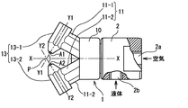
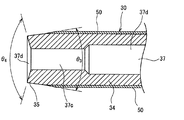
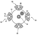
ノズル本体1は、後端をアダプタ2に連結する円筒部10の前端面よりV字状に分岐させた分岐部11(11−1と11ー2)と、これら分岐部11の各先端にそれぞれチップ収納部13(13ー1、13−2)を傾斜させると共に噴射側を近接させて突設している。
The nozzle body 1 has branch portions 11 (11-1 and 11-2) branched in a V shape from the front end surface of the
前記対向するチップ収納部13(13−1、13−2)にノズルチップ3(3−1、3−2)とプラグ4(4−1、4−2)を夫々内嵌し、対向するノズルチップ3(3ー1と3−2)の先端噴射部A(A1、A2)から噴射する噴霧の中心軸線(ノズルチップの中心軸線)Y1−Y1とY2−Y2は、ノズル本体1の円筒部10の中心軸線X−X上の点P1で交差する設定としている。
前記軸線Y1−Y1とY2−Y2がなす対向角θ1は70°〜160°の範囲内に設定し、噴射部A1と点P、A2と点Pの間の距離L2はそれぞれ3〜15mmの範囲内に設定している。
Nozzle tips 3 (3-1, 3-2) and plugs 4 (4-1, 4-2) are fitted in the opposing chip storage portions 13 (13-1, 13-2), respectively, to face the nozzles. The central axes of the sprays (center axes of the nozzle tips) Y1-Y1 and Y2-Y2 from the tip injection section A (A1, A2) of the tip 3 (3-1 and 3-2) are cylindrical portions of the nozzle body 1. It is set to intersect at a point P1 on 10 central axes XX.
The facing angle θ1 formed by the axes Y1-Y1 and Y2-Y2 is set within a range of 70 ° to 160 °, and the distance L2 between the injection unit A1 and the point P and between A2 and the point P is within a range of 3 to 15 mm. Set in.
前記ノズル本体における液体(水)Qと気体(空気)Aとの通路は、まず、アダプタ2には軸芯に沿って気体流入路2aを設けると共に外周面に開口する液体流入路2bを設け、前記分岐部11で、気体流入路2aは気体通路11aと連通し、液体流入路2bは液体通路11bと夫々連通している。
気体通路11aはチップ収納部13内で、ノズルチップ3に設けた外周側の気体通路3aに連通させる共に、液体通路11bはプラグ4に設けた液体通路4aに連通させ、該液体通路4をノズルチップ3の液体通路に連通させている。ノズルチップ3の先端噴射部A(A1、A2)で、前記特許文献1と同様に、外周の気体通路から噴射される気体Aで中心の液体通路3bから液体Qを吸引して気液混合させ、この混合流体を前記点P1で衝突させている。
In the passage between the liquid (water) Q and the gas (air) A in the nozzle body, first, the
The
前記対向配置するノズルチップ3(3ー1、3−2)の形状は同一形状であり、該ノズルチップ3の形状を以下に詳述する。
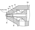
ノズルチップ3は、中央部分に配置すると共に軸芯にそって液体通路を有する第一ノズルチップ30と、該第一ノズルチップ30に噴射側に気体通路をあけて外嵌するとともにノズル本体1のチップ収納部13に内嵌固定する第二ノズルチップ40とからなる。
よって、液体通路と気体通路との仕切壁は第一ノズルチップ30の周壁により形成されると共に、気体通路の外周壁は第二ノズルチップ40によって形成される。
The shape of the nozzle chip 3 (3-1, 3-2) arranged opposite to each other is the same, and the shape of the
The
Therefore, the partition wall between the liquid passage and the gas passage is formed by the peripheral wall of the
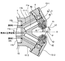
図3に示すように、第一ノズルチップ30は前記プラグ4に連接する大径円筒部31と、該大径円筒部31に連続する中径円筒部32と、該中径円筒部32の前端に円錐筒部33を介して連続する小径の角筒部34を設け、該角筒部34の外形は断面正方形としている。さらに、該角筒部34の噴射側に前端に向けて縮径する円錐筒部35を連続させている。該先端の円錐筒部35の傾斜角度θ3は15°〜40°としている。
As shown in FIG. 3, the
これら大径円筒部31、中径円筒部32、円錐筒部33、角筒部34、円錐筒部35の軸芯に沿って断面円形の液体通路37を設けている。該液体通路37は後端に接続したプラグ4の液体通路4aに連通し、該液体通路4aに分岐部11の液体通路11bを連通させている。よって、液体通路11b、4aを通して第一ノズルチップ30の液体通路37に液体を流入させている。
A
前記液体通路37は、大径筒部31および中径筒部32の軸芯に沿った液体通路37aでは断面積は同一とし、円錐筒部33から角筒部34、円錐筒部35の先端開口近傍までの液体通路37bでは断面積を縮小し、さらに、円錐筒部35の開口端35aに近接した部位では液体通路37cは最小断面積とし、先端の噴射口となる開口端37dでは外面に向けてテーパ状に広げている。図6に示すように、該テーパ角度θ4は90〜170°の範囲としている。
The
前記大径筒部31はチップ収納部13に内嵌し、中央外周面に気体流入凹部31aを設け、該気体流入凹部31aと大径筒部31の前端面31bに連通する気体通路31cを設けている。該気体通路31cは第一ノズルチップ30と第二ノズルチップ40の間の気体通路41に連通させている。
The large-diameter
前記第二ノズルチップ40は大略円錐筒形状で、チップ収納部13の円錐形状とした噴射側周壁13aに凹凸嵌合して内嵌固定し、第一ノズルチップ30の中径筒部32から角筒部34にかけて気体通路41となる空間をあけて外嵌させて取り付けている。また、チップ収容部13の周壁13aの前端面13bより第二ノズルチップ40の前端部40aを突出させ、かつ、該前端部40aの中心より更に前記第一ノズルチップ30の円錐筒部35を所要寸法L3(0.3〜0.8mm)だけ突出させている。
The
第二ノズルチップ40の内周面は、第一ノズルチップ30の大径筒部31の前端面外周に接する後端から角筒部34の後部側にかけて気体通路41を介して外嵌する位置まで円錐面42とし、該円錐面42の前端から開口端40bにかける内周面43は略同一断面の円形断面としている。
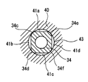
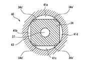
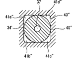
よって、図5に示すように、第二ノズルチップ40の円形の内周面43に第一ノズルチップ30の断面正方形の角筒部34が内嵌し、角筒部34の4つの頂点34c、34d、34e、34fを第二ノズルチップ40の内周面43に当接させている。これにより、内周面43と角筒部34の外面との間に形成する気体通路を4つの気体通路41a〜41dに分離している。これら気体通路41a〜41dは図示のような断面略三日月状となり、これら三日月状の断面積の合計断面積S1と角筒部34の液体通路断面積S2との比は、S1:S2=5:1〜5:2としている。
前記断面三日月状の気体通路の合計断面積S1は0.3〜0.6mm2の範囲が好ましく、液体通路断面積S1は0.08〜0.2mm2の範囲とすることが好ましい。
なお、液体通路は噴射口ではテーパ状に拡径しているため、噴射口(液穴)では0.40〜0.45mm2の範囲となっている。
The inner peripheral surface of the
Therefore, as shown in FIG. 5, the
The total cross-sectional area S1 of the crescent-shaped gas passage is preferably in the range of 0.3 to 0.6 mm 2 , and the liquid passage cross-sectional area S1 is preferably in the range of 0.08 to 0.2 mm 2 .
In addition, since the diameter of the liquid passage is tapered at the injection port, the range of 0.40 to 0.45 mm 2 is obtained at the injection port (liquid hole).
従って、気体は、気体通路41は円錐面42と中径筒部32の間の環状通路41eから、4つに仕切られた気体通路41a〜41dに分流され、該分流状態で第二ノズルチップ40の開口端40bより噴射させている。
なお、図7に示すように、断面正方形状の角筒部34において、外面の各頂点位置にアール面34c’〜3ed’を形成し、該アール面34c’〜34e’を第二ノズルチップ40の内周面43に当接させて、気体通路を4つの通路に仕切ってもよい。
Accordingly, the gas is divided into four
As shown in FIG. 7, in the
また、図6に示すように、前記第一ノズルチップ30の少なくも角筒部34の外周面に、平滑性を有する樹脂被膜50を形成している。また、、図示していないが、第二ノズルチップ40の内周面43にも樹脂被覆を形成している。本実施形態ではテフロン(R)コーテイングしている。
なお、前記ノズルの構成部品をノズルチップも含めてソっ素系樹脂で成形してもよい。
Further, as shown in FIG. 6, a
In addition, you may shape | mold the component parts of the said nozzle including a nozzle tip with a fluorine resin.
前記したように、本実施形態ではノズルに供給する気体Aはコンプレッサーからの圧搾気体(約3kg/cm3)を用い、液体Qとして水を用いている。該水は純水器を通した水を用いているが、必ずしも純水器を通した水に限定されない。
気体Aと液体Qとの気水比は1000未満とし、好ましくは800〜990の範囲で、本実施形態では900としている。
As described above, in this embodiment, the gas A supplied to the nozzle uses the compressed gas (about 3 kg / cm 3 ) from the compressor and water as the liquid Q. The water used is water that has passed through a deionizer, but is not necessarily limited to water that has passed through a deionizer.
The air / water ratio between the gas A and the liquid Q is less than 1000, preferably in the range of 800 to 990, and is 900 in this embodiment.
前記構成からなるノズルの作用について、以下に説明する。
各ノズル噴射部A1、A2では、ノズルチップ3の4つに分かれた気体通路41a〜41dより外方に気体を噴射していると共に、噴射される気体Aの中心位置に、液体通路37の先端開口より液体Qを噴射している。気体Aと液体Qとは外部混合されて液体Qの液滴が微粒化される。さらに、各ノズルチップ3の噴射部A1、A2で混合された気液混合流体が、交差点Pで互いに衝突混合し、この衝突混合で液滴がさらに微粒化され、平均粒子径が10μm以下、即ち、1μm〜10μmで、最大粒子径が50μm以下のドライフォッグとなる。
The operation of the nozzle configured as described above will be described below.
In each nozzle injection part A1, A2, while injecting gas outward from the four
二流体ノズルでは、噴射口近傍、特に気体通路の噴射口近傍において、気体通路の噴射口近傍においてめずまりが発生しやすいが、本実施形態では、噴射口近傍において気体通路を4つの断面三日月形状の気体通路41a〜41dに分けているため、目詰まりが発生しにくくなる。本発明者の実験によると、前記特許文献1のノズルと比較して目詰まり発生率が70〜80%も大幅に低下することが、実験より確認されている。
In the two-fluid nozzle, in the vicinity of the injection port, particularly in the vicinity of the injection port of the gas passage, it is easy to generate a stagnation in the vicinity of the injection port of the gas passage, but in this embodiment, the gas passage has four cross-sectional crescents in the vicinity of the injection port. Since the
その原因は、第一に、各気体通路41a〜41dにおいて、中央部分に広幅部分41a−1ができる一方、両側部に狭幅部分41a−2(41b以下も同じ)が発生し、気体は中央の広幅部分41a−1に流通し、該広幅部分では目詰まりが発生しにくいことにあると認められる。
The reason is that, in each
第二に、気体通路を4つに分断することにより、特許文献1の1つの環状の気体通路の場合と比較して、1つの気体通路の断面積が飛躍的に小さくなるため気体圧が高められる。かつ、第一ノズルチップ30の先端の円錐筒部35は第二ノズルチップ40の前端面より外方に突出させ、4つの気体通路41a〜41dの断面積を噴射口近傍で拡大させていないため、噴射直前で圧力を低下させず、圧力気体を噴射させ、液体Qと外部混合させることができる。その結果、供給する気体量を減少させて気水比を1000未満の900としても、噴射される平均粒子径を10μm以下とできた。このように、気水比を1000未満として、噴射される噴霧の乾燥度を低下させていること、および、気体通路への気体供給量を減少させることができたことからも、気体中の不純物による目詰まり発生が抑制されたと認められる。
Secondly, by dividing the gas passage into four, compared with the case of one annular gas passage of Patent Document 1, the cross-sectional area of one gas passage is drastically reduced, so the gas pressure is increased. It is done. And the
第三に、気体通路41a〜41dの周面(角筒部34の外面と第二ノズルチップ40の内周面43にテフロン(R)コーテイングを施し、不純物が付着しにくい構成としていることが、目詰まり発生を抑制したと認められる。
Thirdly, Teflon (R) coating is applied to the peripheral surfaces of the
また、本発明では、前記したように、噴射口に開口する気体通路を4つに仕切り、各気体通路を流通する気体量を減少させているため、噴霧時に発生する音を低減することができる。
さらに、気水比を1000未満の900としていることにより、使用する圧搾気体量を低減でき、コスト低減を図ることができる。なお、供給する気体はコンプレッサーからの圧搾気体に限定されず、ブロアから供給される気体でもよい。
さらにまた、かつ、第一ノズルチップ30の角筒部34が四カ所で第二ノズルチップ40の内周面43と接することにより、第一ノズルチップ30の全周を気体通路をあけて第二ノズルチップ40の内部に配置する場合と比較して、第一ノズルチップ30を安定して支持できるとともに、組付け作業も容易となる。
Further, in the present invention, as described above, since the gas passages opening to the injection port are divided into four and the amount of gas flowing through each gas passage is reduced, the sound generated during spraying can be reduced. .
Furthermore, by setting the air / water ratio to 900, which is less than 1000, the amount of compressed gas to be used can be reduced, and the cost can be reduced. In addition, the gas supplied is not limited to the compressed gas from a compressor, The gas supplied from a blower may be sufficient.
Furthermore, the
図8は第2実施形態を示し、第1実施形態ではノズルチップを第一ノズルチップ30と第二ノズルチップ40との2部材より形成しているが、第二ノズルチップ40に相当する部分をノズル本体1のチップ収容部11に一体的に形成している。即ち、ノズルチップは第一ノズルチップ30のみとしている。
即ち、液体通路と気体通路との仕切壁は第1実施形態と同様に第一ノズルチップ30の周壁で形成しているが、気体通路の外周壁はノズル本体のチップ収納部の周壁で形成している。
FIG. 8 shows the second embodiment. In the first embodiment, the nozzle tip is formed of two members, the
That is, the partition wall between the liquid passage and the gas passage is formed by the peripheral wall of the
該第2実施形態では、ノズル本体1のチップ収納部13’には、ノズルチップ30の大径筒部31を嵌合する穴部13’の前側に円錐穴部13b’を段部13c’に介して連続させ、該円錐穴部13b’の円端に断面円形の小径穴部13d’を形成している。該小径穴部13d’の内周面にノズルチップ30の角筒部34の内嵌させ、第1実施形態と同様に4カ所で当接させて、気体通路41を分離された4つの気体通路41a〜41dとしている。他の構成は第1実施形態と同様であるため、説明を省略する。
In the second embodiment, the
前記第2実施形態の構成としても、第二ノズルチップをノズル本体に一体的に形成した点だけが相違するため、作用効果は第1実施形態と同様である。
また、ノズル本体の加工あるいは成形が複雑となるが、部品点数が減少し、組立工数が減少する利点がある。
The configuration of the second embodiment is different from that of the first embodiment only in that the second nozzle tip is formed integrally with the nozzle body.
In addition, processing or molding of the nozzle body is complicated, but there is an advantage that the number of parts is reduced and the number of assembly steps is reduced.
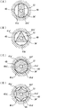
図9(A)〜(D)は分離する気体通路の他の実施形態を示す。
即ち、第1実施形態および第2実施形態では第一ノズルチップ30の角筒部34の外形を断面正方形とし、気体通路を4つに分割しているが、他の実施形態に示すように、噴射口側の気体通路を2分割、3分割、6分割としている。なお、気体通路の分割個数は8分割程度が上限で、分割し過ぎると、1つの気体通路の断面積が小さくなりすぎ、所要気体量を供給するにはノズルチップの断面積が大きくなり過ぎるとともに、各気体通路が最大幅部の面積が小さくなり逆に目詰まりが発生しやすくなる。
図9(A)〜(D)では第二ノズルチップ40の内周面43は円形とし、第一ノズルチップ30の角筒部の軸芯部には断面円形の液体通路37を設けている点は共通している。
なお、第二ノズルチップを設けずに、第2実施形態と同様に、第二ノズルチップをノズル本体のチップ収納部に一体的に設けてもよい。
9 (A) to 9 (D) show another embodiment of gas passages for separation.
That is, in the first embodiment and the second embodiment, the outer shape of the
9A to 9D, the inner
In addition, you may provide a 2nd nozzle chip integrally in the chip | tip storage part of a nozzle main body similarly to 2nd Embodiment, without providing a 2nd nozzle chip.
図9(A)の角筒部34’は対向する2辺を直線状とし直交する2辺は円弧面とし、気体通路を対向する2個の気体通路41a’と41b’に分割している。
図9(B)の角筒部34’を断面三角形とし、3つの頂点を内周面43に当接させ、気体通路を3つの気体通路41a’〜41c’に分割している。
図9(C)の角筒部34’を断面六角形とし、6この頂点を内周面43に当接させ、気体通路を6つの気体通路41a’〜41f’に分割している。
図9(D)の角筒部34’の外周面に周方向に6個の凹部を設けるとともに6つの頂点を突出させた星型類似形状とし、6つの頂点を内周面43に当接させて、気体通路を6つの気体通路41a’〜41f’に分割している。
いずれの形状としても、分割した気体通路の断面積の合計面積S1と角筒部34の中心液体通路の断面積S2とは、前記したS1:S2=5:1〜5:2の関係としている。
In the rectangular tube portion 34 'of FIG. 9A, two opposing sides are linear and two orthogonal sides are arcuate surfaces, and the gas passage is divided into two opposing
The rectangular tube portion 34 'in FIG. 9 (B) has a triangular cross section, the three apexes are brought into contact with the inner
9C has a hexagonal cross section, and 6 apexes abut on the inner
In FIG. 9D, the outer peripheral surface of the
In any shape, the total area S1 of the cross-sectional areas of the divided gas passages and the cross-sectional area S2 of the central liquid passage of the
図10は第3実施形態を示し、噴射口側での気体通路の分割を、第二ノズルチップ40”の穴形状を四角穴とし、内面43”を4つの直線面から形成している。一方、第一ノズルチップ30側は、角筒部を断面円形の円筒部34”としている。該円筒部34”の外円は四角穴の内面43に対する外接円と、円筒部34”と四角穴の内面43との間に4つに仕切られた気体通路41a”〜41d”を設けている。なお、第二ノズルチップ40に設ける角孔はいずれもエッジ部に大きなアールを設けている。
FIG. 10 shows a third embodiment, in which the gas passage is divided on the injection port side, the hole shape of the
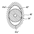
図11は第3実施形態の変形例を示し、第二ノズルチップ40’の穴形状を楕円穴とし、第一チップチップに円筒部34”との間に2個の仕切られた気体通路41a”、41b”を形成している。
FIG. 11 shows a modification of the third embodiment, wherein the hole shape of the
図10および図11に示すように、第一ノズルチップ30を円筒部34”とし、第二ノズルチップ40”に角穴を設けて、噴射口側の気体通路を複数の分割しても、第1実施形態と同様の作用効果を得られる。
As shown in FIGS. 10 and 11, even if the
前記第3実施形態においても、第1実施形態の第2変形例と同様に、第二ノズルチップ40”を設けずに、ノズル本体のノズル収容部と一体的に設けてもよい。
Also in the third embodiment, similarly to the second modification of the first embodiment, the
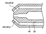
図12は第4実施形態を示し、気体通路を分離通路としている部分において、各分離された気体通路41a〜41dを液体噴射口側に向けて傾斜させている。各分離された気体通路の断面積は通路軸線方向に対して直交方向で同一としている。
前記構造とすると、気体通路先端の噴射口から気体が中心の液体側に向けて噴射され、より液体と気体の混合を促進して、液滴の微粒化を図ることができる。
FIG. 12 shows a fourth embodiment in which the separated
With the above structure, the gas is ejected from the ejection port at the tip of the gas passage toward the center liquid side, and the mixing of the liquid and the gas is further promoted, so that the droplets can be atomized.
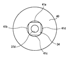
図13は第5実施形態を示し、第1〜第4実施形態と相違し、気体通路を周方向に仕切らずに断面円環形状の気体通路410としている。即ち、第1実施形態では第一ノズルチップ30の角筒部34であったところを、第一ノズルチップ300では円筒部340として外周面を断面円形としている。これにより、第二ノズルチップ400の断面円形の内周面との間に周方向に仕切られていない気体通路410をを設けている。他の構成は第1実施形態と同一であるため同一符号を付して説明を省略する。
該第5実施形態では、気水比を1000未満、好ましくは900〜800としている。
このように、気体通路を仕切らずに環状としても、気水比を1000未満、好ましくは900〜800程度として、空気量を低減することで気体通路400内で目詰まりが発生するのを抑制出来ると共に発生する騒音を低減できる。他の作用効果は第1実施形態と同様であるため、説明を省略する。
FIG. 13 shows a fifth embodiment. Unlike the first to fourth embodiments, the gas passage is formed as a
In the fifth embodiment, the air / water ratio is less than 1000, preferably 900 to 800.
In this way, even if the gas passage is annular without being partitioned, it is possible to suppress clogging in the gas passage 400 by reducing the amount of air by setting the air / water ratio to less than 1000, preferably about 900 to 800. And noise generated with it can be reduced. Since other operations and effects are the same as those of the first embodiment, description thereof is omitted.
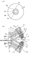
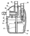
図14および図16は第6実施形態を示し、第1実施形態のノズル50を加湿器60の外周面に90度間隔をあけて4つ設けている。加湿器60の構造は本出願人の特許第2843970の構造と同一構造としている。図中、51は加湿器60の本体ケース、52は蓋ケース、53は液供給管、54が気体供給管、55が貯水室、56は貯水室内の液量を制御するフロート、57は水吸上管、58は気体通路、59は液体通路である。
14 and 16 show a sixth embodiment, in which four
前記加湿器60では貯水内55内の水が水吸上管57より液体通路59に吸い上げられ、ノズル50の前記第1実施形態に記載の液体通路へ流入する一方、気体は気体通路58を通ってノズル50の気体通路へ流入し、第1実施形態で説明したように、対向配置されるノズル収納部11−1、11−2の先端から気体と水の混合流体が噴射され、これら混合流体が衝突混合され、平均粒径10μm以下の超微霧が発生する。
In the
本発明のノズルは、加湿器、空調機、あるいは冷却、鎮埃、液切り、消毒液や燃料油の噴霧等の工業的用途に用いる部品に取り付けられ、濡れを発生させずに液体を噴霧させる必要がある機器に好適に用いられる。 The nozzle of the present invention is attached to a humidifier, an air conditioner, or a part used for industrial use such as cooling, dust removal, liquid draining, spraying of disinfectant liquid or fuel oil, and sprays liquid without causing wetting. It is suitably used for devices that need it.
1 ノズル本体
2 アダプタ
3 ノズルチップ
4 プラグ
11 分岐部
13 チップ収納部
30 第一ノズルチップ
34 角筒部
37 液体通路
40 第二ノズルチップ
41 気体通路
41a〜41d 分離された気体通路
42 内周面
50 ノズル
60 加湿器
DESCRIPTION OF SYMBOLS 1 Nozzle
Claims (13)
前記仕切壁の噴射口側の外形を断面多角形状、長円状あるいは楕円状の異形とする一方、前記気体通路の外周面を断面円形として、該断面円形の外周面に前記仕切壁の異形の外面を複数箇所で当接させて前記噴射側の気体通路を周方向に複数の気体通路に分離させ、あるいは
前記仕切壁の外面を断面円形とする一方、前記気体通路の噴射口側の外周面を断面多角形状、長円状あるいは楕円状の異形として前記仕切壁の外周面を面に複数箇所で当接させ、前記噴射側の気体通路を周方向に複数の気体通路に分離させ、
前記液体通路から噴射する液体の外周に前記分離させた複数の気体通路の噴射口から噴射する気体を混合させて噴霧を発生させていることを特徴とする超微霧噴射ノズル。 A gas passage is provided on the outer peripheral side of the liquid passage via a partition wall, and the gas passage communicating with the injection port is
While the outer shape of the partition wall on the injection port side is a polygonal cross-sectional shape, an elliptical shape or an elliptical shape, the outer peripheral surface of the gas passage is a circular shape, and the outer peripheral surface of the cross-sectional circle has an irregular shape of the partition wall. The outer surface abuts at a plurality of locations to separate the gas passage on the injection side into a plurality of gas passages in the circumferential direction, or the outer surface of the partition wall has a circular cross section, while the outer peripheral surface on the injection port side of the gas passage A cross-sectional polygonal shape, an elliptical shape or an elliptical shape, the outer peripheral surface of the partition wall abuts the surface at a plurality of locations, the gas passage on the injection side is separated into a plurality of gas passages in the circumferential direction,
An ultrafine mist injection nozzle characterized in that spray is generated by mixing the gas injected from the outlets of the plurality of separated gas passages on the outer periphery of the liquid injected from the liquid passage.
前記液体通路と気体通路とを備えた噴射部を所要間隔および所要角度をあけて対向配置し、各噴射部で外部混合される気液混合流体同士を衝突混合させ、液滴の平均粒子径を1μm〜10μmの範囲で、最大粒子径を50μm以下としている請求項1に記載の超微霧噴射ノズル。 The liquid channel injection port protrudes outward from the gas channel injection port, and gas is injected from the gas channel injection port to the outer periphery of the liquid sprayed from the liquid channel, so that the liquid and the gas are externally supplied. Mix and
The jetting part having the liquid passage and the gas passage is arranged to face each other with a required interval and a required angle, and the gas-liquid mixed fluid mixed externally in each jetting part is collided and mixed, and the average particle diameter of the droplet is determined. The ultrafine mist injection nozzle according to claim 1, wherein the maximum particle size is 50 μm or less in a range of 1 μm to 10 μm.
該第一ノズルチップと前記チップ収納部の内周面の間、あるいは前記チップ収納部に嵌合する第二ノズルチップと前記第一ノズルチップの間に前記気体通路を形成し、前記気体通路の外周壁を前記チップ収納部あるいは前記第二ノズルチップで形成している請求項1または請求項2に記載の超微霧噴射ノズル。 The liquid passage is formed along the axis of the first nozzle tip that fits into the tip storage portion of the nozzle body, while the partition wall is formed by the peripheral wall of the first nozzle tip,
The gas passage is formed between the first nozzle chip and the inner peripheral surface of the chip storage section, or between the second nozzle chip and the first nozzle chip fitted to the chip storage section, The ultra fine mist injection nozzle according to claim 1 or 2, wherein an outer peripheral wall is formed by the tip storage portion or the second nozzle tip.
前記複数の気体通路の合計断面積S1、該気体通路に囲まれた部位の前記液体通路の断面積S2とすると、S1:S2を5:1〜5:2の範囲に設定している請求項1乃至請求項3のいずれか1項に記載の超微霧噴射ノズル。 Each cross-sectional area of the plurality of gas passages is the same cross-sectional area, and
S1: S2 is set in a range of 5: 1 to 5: 2, where a total cross-sectional area S1 of the plurality of gas passages and a cross-sectional area S2 of the liquid passage in a portion surrounded by the gas passages are set. The ultrafine mist injection nozzle according to any one of claims 1 to 3.
前記液体通路と気体通路とを備えた噴射部を対向配置し、該対向配置する噴射部の軸線がなす角度を70゜〜160゜、これら各噴射口から衝突点までの距離を3〜15mmに設定し、各噴射部で外部混合される気液混合流体同士を衝突混合させ、液滴の平均粒子径を1μm〜10μmの範囲で、最大粒子径を50μm以下とし、
前記液体通路に供給する液体と気体通路に供給する気体との気水比(気体体積/液体体積)を1000未満800以上にせていしていることを特徴とする超微霧噴射ノズル。 A gas passage provided with a resin portion that forms a smooth surface at least on the inner peripheral surface is provided on the outer peripheral side of the liquid passage, and the ejection opening of the liquid passage is 0.3 to 0.8 mm outside the ejection opening of the gas passage. Projecting toward the outside, jetting gas from the jet port of the gas passage to the outer periphery of the liquid jetted from the liquid passage, and externally mixing the liquid and gas,
An injection section having the liquid passage and the gas passage is arranged opposite to each other, the angle formed by the axis of the injection section arranged opposite to each other is set to 70 ° to 160 °, and the distance from each of the injection ports to the collision point is set to 3 to 15 mm. Set and collide and mix the gas-liquid mixed fluids externally mixed in each injection unit, the average particle diameter of the droplets is in the range of 1 μm to 10 μm, the maximum particle diameter is 50 μm or less,
An ultrafine mist injection nozzle, characterized in that an air-water ratio (gas volume / liquid volume) between a liquid supplied to the liquid passage and a gas supplied to the gas passage is less than 1000 and 800 or more.
Priority Applications (2)
| Application Number | Priority Date | Filing Date | Title |
|---|---|---|---|
| JP2004119566A JP2005296874A (en) | 2004-04-14 | 2004-04-14 | Supermicromist spray nozzle |
| TW094117473A TW200640580A (en) | 2004-04-14 | 2005-05-27 | Ultra-fine spray-jetting nozzle |
Applications Claiming Priority (1)
| Application Number | Priority Date | Filing Date | Title |
|---|---|---|---|
| JP2004119566A JP2005296874A (en) | 2004-04-14 | 2004-04-14 | Supermicromist spray nozzle |
Publications (1)
| Publication Number | Publication Date |
|---|---|
| JP2005296874A true JP2005296874A (en) | 2005-10-27 |
Family
ID=35329065
Family Applications (1)
| Application Number | Title | Priority Date | Filing Date |
|---|---|---|---|
| JP2004119566A Pending JP2005296874A (en) | 2004-04-14 | 2004-04-14 | Supermicromist spray nozzle |
Country Status (2)
| Country | Link |
|---|---|
| JP (1) | JP2005296874A (en) |
| TW (1) | TW200640580A (en) |
Cited By (19)
| Publication number | Priority date | Publication date | Assignee | Title |
|---|---|---|---|---|
| JP2005313049A (en) * | 2004-04-28 | 2005-11-10 | Atomakkusu:Kk | Fine particle injection device |
| JP2006198480A (en) * | 2005-01-18 | 2006-08-03 | Soken Kogyo Kk | Nozzle for spray type vaporizer |
| JP2007181802A (en) * | 2006-01-10 | 2007-07-19 | Fuji Paudal Co Ltd | Spray nozzle and insert |
| JP2008168179A (en) * | 2007-01-09 | 2008-07-24 | Honda Motor Co Ltd | Coating apparatus and method, and chip mounted on the coating apparatus |
| JP2008289986A (en) * | 2007-05-23 | 2008-12-04 | Terumo Corp | Applicator |
| JP2008546524A (en) * | 2005-06-13 | 2008-12-25 | ヴィクトリック カンパニー | High speed and low pressure emitter |
| JP2009122027A (en) * | 2007-11-16 | 2009-06-04 | Yokohama Rubber Co Ltd:The | Method and apparatus for dynamical friction testing of vulcanized rubber |
| JP2010127603A (en) * | 2008-12-01 | 2010-06-10 | Ikeuchi:Kk | Nozzle and humidifier including the nozzle |
| JP2011125769A (en) * | 2009-12-15 | 2011-06-30 | Meiji Kikai Seisakusho:Kk | Air spray gun |
| DE102013109345A1 (en) | 2012-09-05 | 2014-03-06 | Denso Corporation | Cleaning method and cleaning device |
| JP2014233650A (en) * | 2013-05-31 | 2014-12-15 | 関西ペイント株式会社 | Coating head and coating device |
| JP2015500135A (en) * | 2011-11-18 | 2015-01-05 | アリゾナ ボード オブ リージェンツ ア ボディー コーポレート アクティング オン ビハーフ オブ アリゾナ ステイト ユニバーシティARIZONA BOARD OF REGENTS,a body corporate acting on behalf of ARIZONA STATE UNIVERSITY | System and method for providing a micron scale continuous liquid jet |
| US9821325B2 (en) | 2013-04-30 | 2017-11-21 | Arizona Board Of Regents On Behalf Of Arizona State University | Apparatus and methods for lipidic cubic phase (LCP) injection for membrane protein investigations |
| CN110641154A (en) * | 2019-09-29 | 2020-01-03 | 广东思谷智能技术有限公司 | Solidification degree adjustable multiple air current auxiliary electrofluid nozzle |
| KR20200004333A (en) | 2017-07-21 | 2020-01-13 | 스프레이잉 시스템스 재팬 고도가이샤 | 2 fluid nozzle |
| CN114561515A (en) * | 2022-03-22 | 2022-05-31 | 杨岚 | Quenching device and quenching process |
| JP2023175228A (en) * | 2022-05-30 | 2023-12-12 | ノズルネットワーク株式会社 | Two-fluid spray device |
| JP2024000352A (en) * | 2022-06-20 | 2024-01-05 | 株式会社マキタ | Method for manufacturing a mist blower and a liquid nozzle used therein |
| WO2025221107A1 (en) * | 2024-04-16 | 2025-10-23 | 서울대학교병원 | Two-fluid nozzle |
Families Citing this family (1)
| Publication number | Priority date | Publication date | Assignee | Title |
|---|---|---|---|---|
| TWI458559B (en) * | 2011-02-09 | 2014-11-01 | China Steel Corp | Gas-liquid nozzle device |
Citations (4)
| Publication number | Priority date | Publication date | Assignee | Title |
|---|---|---|---|---|
| JPS52104965U (en) * | 1976-02-05 | 1977-08-10 | ||
| JPS62289257A (en) * | 1986-06-09 | 1987-12-16 | Ikeuchi:Kk | Hyperfine mist injection nozzle |
| JP2003010330A (en) * | 2001-07-02 | 2003-01-14 | Nipro Corp | Spray head for bioadhesive administration |
| JP2003220353A (en) * | 2002-01-29 | 2003-08-05 | Tokyo Autom Mach Works Ltd | Paste jetting nozzle and paste coating device |
-
2004
- 2004-04-14 JP JP2004119566A patent/JP2005296874A/en active Pending
-
2005
- 2005-05-27 TW TW094117473A patent/TW200640580A/en unknown
Patent Citations (4)
| Publication number | Priority date | Publication date | Assignee | Title |
|---|---|---|---|---|
| JPS52104965U (en) * | 1976-02-05 | 1977-08-10 | ||
| JPS62289257A (en) * | 1986-06-09 | 1987-12-16 | Ikeuchi:Kk | Hyperfine mist injection nozzle |
| JP2003010330A (en) * | 2001-07-02 | 2003-01-14 | Nipro Corp | Spray head for bioadhesive administration |
| JP2003220353A (en) * | 2002-01-29 | 2003-08-05 | Tokyo Autom Mach Works Ltd | Paste jetting nozzle and paste coating device |
Cited By (22)
| Publication number | Priority date | Publication date | Assignee | Title |
|---|---|---|---|---|
| JP2005313049A (en) * | 2004-04-28 | 2005-11-10 | Atomakkusu:Kk | Fine particle injection device |
| JP2006198480A (en) * | 2005-01-18 | 2006-08-03 | Soken Kogyo Kk | Nozzle for spray type vaporizer |
| JP2008546524A (en) * | 2005-06-13 | 2008-12-25 | ヴィクトリック カンパニー | High speed and low pressure emitter |
| JP2007181802A (en) * | 2006-01-10 | 2007-07-19 | Fuji Paudal Co Ltd | Spray nozzle and insert |
| JP2008168179A (en) * | 2007-01-09 | 2008-07-24 | Honda Motor Co Ltd | Coating apparatus and method, and chip mounted on the coating apparatus |
| JP2008289986A (en) * | 2007-05-23 | 2008-12-04 | Terumo Corp | Applicator |
| JP2009122027A (en) * | 2007-11-16 | 2009-06-04 | Yokohama Rubber Co Ltd:The | Method and apparatus for dynamical friction testing of vulcanized rubber |
| JP2010127603A (en) * | 2008-12-01 | 2010-06-10 | Ikeuchi:Kk | Nozzle and humidifier including the nozzle |
| JP2011125769A (en) * | 2009-12-15 | 2011-06-30 | Meiji Kikai Seisakusho:Kk | Air spray gun |
| JP2015500135A (en) * | 2011-11-18 | 2015-01-05 | アリゾナ ボード オブ リージェンツ ア ボディー コーポレート アクティング オン ビハーフ オブ アリゾナ ステイト ユニバーシティARIZONA BOARD OF REGENTS,a body corporate acting on behalf of ARIZONA STATE UNIVERSITY | System and method for providing a micron scale continuous liquid jet |
| DE102013109345A1 (en) | 2012-09-05 | 2014-03-06 | Denso Corporation | Cleaning method and cleaning device |
| US9533333B2 (en) | 2012-09-05 | 2017-01-03 | Denso Corporation | Cleaning method and cleaning apparatus |
| US9821325B2 (en) | 2013-04-30 | 2017-11-21 | Arizona Board Of Regents On Behalf Of Arizona State University | Apparatus and methods for lipidic cubic phase (LCP) injection for membrane protein investigations |
| JP2014233650A (en) * | 2013-05-31 | 2014-12-15 | 関西ペイント株式会社 | Coating head and coating device |
| KR20200004333A (en) | 2017-07-21 | 2020-01-13 | 스프레이잉 시스템스 재팬 고도가이샤 | 2 fluid nozzle |
| CN110641154A (en) * | 2019-09-29 | 2020-01-03 | 广东思谷智能技术有限公司 | Solidification degree adjustable multiple air current auxiliary electrofluid nozzle |
| CN110641154B (en) * | 2019-09-29 | 2023-10-27 | 武汉国创科光电装备有限公司 | Multi-airflow auxiliary electrofluidic spray head with adjustable solidification degree |
| CN114561515A (en) * | 2022-03-22 | 2022-05-31 | 杨岚 | Quenching device and quenching process |
| JP2023175228A (en) * | 2022-05-30 | 2023-12-12 | ノズルネットワーク株式会社 | Two-fluid spray device |
| JP7833179B2 (en) | 2022-05-30 | 2026-03-19 | ノズルネットワーク株式会社 | Two-fluid spray device |
| JP2024000352A (en) * | 2022-06-20 | 2024-01-05 | 株式会社マキタ | Method for manufacturing a mist blower and a liquid nozzle used therein |
| WO2025221107A1 (en) * | 2024-04-16 | 2025-10-23 | 서울대학교병원 | Two-fluid nozzle |
Also Published As
| Publication number | Publication date |
|---|---|
| TW200640580A (en) | 2006-12-01 |
Similar Documents
| Publication | Publication Date | Title |
|---|---|---|
| JP2005296874A (en) | Supermicromist spray nozzle | |
| JP2710398B2 (en) | Two-fluid nozzle | |
| JP6487041B2 (en) | Atomizer nozzle | |
| US20060065765A1 (en) | Fluidic nozzle for trigger spray applications | |
| KR20070020248A (en) | Fine water spraying head | |
| US20060283985A1 (en) | Ultra-fine spray-jetting nozzle | |
| CN110170392A (en) | spray device | |
| CN103212499A (en) | Multi-section type atomizing nozzle for oil film with water drops | |
| TW200417417A (en) | Ejection device of ejecting gas-liquid mixed flow | |
| JP7104006B2 (en) | Bubble generator | |
| JPH09220495A (en) | Fluid ejection nozzle | |
| JP2017531553A (en) | Two-fluid nozzle | |
| JP2011098284A (en) | Nozzle for mixing gas and liquid | |
| JP4239879B2 (en) | Micro-mist generation method and apparatus | |
| JP5270317B2 (en) | Nozzle for cleaning | |
| KR20060128289A (en) | Ultra Fine Spray Spray Nozzles | |
| JP5496761B2 (en) | Two-fluid nozzle | |
| JP2006346611A (en) | Washing liquid spraying apparatus | |
| US12285769B2 (en) | Pulsating spray cleaning nozzle assembly and method | |
| EP1731225A1 (en) | Ultra-fine spray nozzle with intersecting jets | |
| JP2001269603A (en) | Fluid injection nozzle | |
| JP4504641B2 (en) | Spray nozzle and spraying method using the same | |
| KR102497047B1 (en) | Nozzle structure | |
| JPH0315493B2 (en) | ||
| JP2004344689A (en) | Two-fluid nozzle |
Legal Events
| Date | Code | Title | Description |
|---|---|---|---|
| A621 | Written request for application examination |
Free format text: JAPANESE INTERMEDIATE CODE: A621 Effective date: 20070226 |
|
| A977 | Report on retrieval |
Free format text: JAPANESE INTERMEDIATE CODE: A971007 Effective date: 20091221 |
|
| A131 | Notification of reasons for refusal |
Free format text: JAPANESE INTERMEDIATE CODE: A131 Effective date: 20100119 |
|
| A02 | Decision of refusal |
Free format text: JAPANESE INTERMEDIATE CODE: A02 Effective date: 20100525 |