EP0248743B1 - Dispositif de connexion autodénudant - Google Patents
Dispositif de connexion autodénudant Download PDFInfo
- Publication number
- EP0248743B1 EP0248743B1 EP87420120A EP87420120A EP0248743B1 EP 0248743 B1 EP0248743 B1 EP 0248743B1 EP 87420120 A EP87420120 A EP 87420120A EP 87420120 A EP87420120 A EP 87420120A EP 0248743 B1 EP0248743 B1 EP 0248743B1
- Authority
- EP
- European Patent Office
- Prior art keywords
- sleeve
- tubular
- screw
- connection
- parallel
- Prior art date
- Legal status (The legal status is an assumption and is not a legal conclusion. Google has not performed a legal analysis and makes no representation as to the accuracy of the status listed.)
- Expired - Lifetime
Links
Images

Classifications
-
- H—ELECTRICITY
- H01—ELECTRIC ELEMENTS
- H01R—ELECTRICALLY-CONDUCTIVE CONNECTIONS; STRUCTURAL ASSOCIATIONS OF A PLURALITY OF MUTUALLY-INSULATED ELECTRICAL CONNECTING ELEMENTS; COUPLING DEVICES; CURRENT COLLECTORS
- H01R11/00—Individual connecting elements providing two or more spaced connecting locations for conductive members which are, or may be, thereby interconnected, e.g. end pieces for wires or cables supported by the wire or cable and having means for facilitating electrical connection to some other wire, terminal, or conductive member, blocks of binding posts
- H01R11/11—End pieces or tapping pieces for wires, supported by the wire and for facilitating electrical connection to some other wire, terminal or conductive member
- H01R11/20—End pieces terminating in a needle point or analogous contact for penetrating insulation or cable strands
-
- H—ELECTRICITY
- H01—ELECTRIC ELEMENTS
- H01R—ELECTRICALLY-CONDUCTIVE CONNECTIONS; STRUCTURAL ASSOCIATIONS OF A PLURALITY OF MUTUALLY-INSULATED ELECTRICAL CONNECTING ELEMENTS; COUPLING DEVICES; CURRENT COLLECTORS
- H01R13/00—Details of coupling devices of the kinds covered by groups H01R12/70 or H01R24/00 - H01R33/00
- H01R13/46—Bases; Cases
- H01R13/502—Bases; Cases composed of different pieces
- H01R13/512—Bases; Cases composed of different pieces assembled by screw or screws
-
- H—ELECTRICITY
- H01—ELECTRIC ELEMENTS
- H01R—ELECTRICALLY-CONDUCTIVE CONNECTIONS; STRUCTURAL ASSOCIATIONS OF A PLURALITY OF MUTUALLY-INSULATED ELECTRICAL CONNECTING ELEMENTS; COUPLING DEVICES; CURRENT COLLECTORS
- H01R13/00—Details of coupling devices of the kinds covered by groups H01R12/70 or H01R24/00 - H01R33/00
- H01R13/66—Structural association with built-in electrical component
-
- H—ELECTRICITY
- H01—ELECTRIC ELEMENTS
- H01R—ELECTRICALLY-CONDUCTIVE CONNECTIONS; STRUCTURAL ASSOCIATIONS OF A PLURALITY OF MUTUALLY-INSULATED ELECTRICAL CONNECTING ELEMENTS; COUPLING DEVICES; CURRENT COLLECTORS
- H01R4/00—Electrically-conductive connections between two or more conductive members in direct contact, i.e. touching one another; Means for effecting or maintaining such contact; Electrically-conductive connections having two or more spaced connecting locations for conductors and using contact members penetrating insulation
- H01R4/24—Connections using contact members penetrating or cutting insulation or cable strands
- H01R4/2416—Connections using contact members penetrating or cutting insulation or cable strands the contact members having insulation-cutting edges, e.g. of tuning fork type
- H01R4/2445—Connections using contact members penetrating or cutting insulation or cable strands the contact members having insulation-cutting edges, e.g. of tuning fork type the contact members having additional means acting on the insulation or the wire, e.g. additional insulation penetrating means, strain relief means or wire cutting knives
- H01R4/2458—Connections using contact members penetrating or cutting insulation or cable strands the contact members having insulation-cutting edges, e.g. of tuning fork type the contact members having additional means acting on the insulation or the wire, e.g. additional insulation penetrating means, strain relief means or wire cutting knives the contact members being in a slotted tubular configuration, e.g. slotted tube-end
-
- H—ELECTRICITY
- H01—ELECTRIC ELEMENTS
- H01R—ELECTRICALLY-CONDUCTIVE CONNECTIONS; STRUCTURAL ASSOCIATIONS OF A PLURALITY OF MUTUALLY-INSULATED ELECTRICAL CONNECTING ELEMENTS; COUPLING DEVICES; CURRENT COLLECTORS
- H01R4/00—Electrically-conductive connections between two or more conductive members in direct contact, i.e. touching one another; Means for effecting or maintaining such contact; Electrically-conductive connections having two or more spaced connecting locations for conductors and using contact members penetrating insulation
- H01R4/24—Connections using contact members penetrating or cutting insulation or cable strands
- H01R4/2416—Connections using contact members penetrating or cutting insulation or cable strands the contact members having insulation-cutting edges, e.g. of tuning fork type
Definitions
- Patent FR-A-2,541,049 relates to a device of this kind, characterized in that the tubular connection element has a first split end part whose external transverse dimensions are such that it can penetrate into the second split end part of another tubular connection element, similar to the first, guide means being provided between at least one interior part of the insulating support, and each tubular connection element that it supports, to allow relative movement, axial but not angular , between the insulating support and each tubular element, displacement means being provided, individually for each tubular connection element, to ensure by this relative axial displacement, the connection, respectively the connection and the disconnection, between at least one of the two transverse slots of the latter, slot which extends through the two opposite thereof, and at least one conductor dis placed in the corresponding passage which extends transversely to the insulating support in the extension of each of the two ends of the transverse slot.
- the devices of this type described and represented in patent FR-A-2,541,049 are generally equipped with an operating member, such as a screw, by tubular connection element, or by stacking of tubular connection elements inserted. into each other.
- an operating member such as a screw
- tubular connection element or by stacking of tubular connection elements inserted. into each other.
- connection device overcomes these drawbacks. It is characterized in that it comprises two identical and parallel tubular connection elements, or two parallel and identical stacks of nesting tubular connection elements, both having a common insulating support, said common insulating support being constituted by a half lower sleeve mounted on a common electrically conductive base connected to the earth of the installation, and an insulating upper half-sleeve covering the two parallel tubular elements, or the two parallel stacks of nesting tubular elements, this upper half-sleeve being traversed , parallel to the two tubular elements or tubular stacks, and between them, by an electrically conductive screw, arranged so as to be able, by coming to be screwed into a corresponding threaded orifice of said common conductive base, ensuring the bringing together of said upper and lower half-sockets.
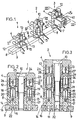
- Each of the modules 1,2,3 shown differs from the modules described in patent FR-A-2,541,049 by the fact that it is always double, that is to say that it comprises two devices according to the patent FR-A-2.541.049 parallel and coupled, that its lower insulating support is constituted by a double piece 8, intended to receive the two lower wires, which is fixed on a common metal bar 9, or metal base, connected to earth of the installation, and that the displacement means making it possible, by respective approximation of the upper half-socket 4 and the lower half-socket 8, to tighten the module and thereby ensure the insulation displacement connection of the lower wires and / or higher, is made up by a metal screw 10 crossing from top to bottom the central part of the module, between the two parallel tubular elements and the two parallel stacks of nesting tubular elements, to be screwed into the metal base 9 and thereby ensure the tightening vertical of the different half-sockets 4,8 or 4,5,8, or 4,6,8 constituting the module 1,2 or
- FIG. 2 represents the simplest module 1, as it is delivered to the user before any assembly of wires.
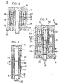
- the common insulating half-sleeve 4 which covers the entire module and receives the head of the central metal screw 10, the latter being screwed into the metal bar 9 to ensure the tightening of the cover 4 against the lower insulating half-sleeve 8, the latter being mounted, by fixing members 11 which are difficult to remove, on the bar 9 as shown.
- the upper half-sleeve 4 obviously includes two tubular channels 12, 13 intended to receive the two upper wires to be connected, and likewise the lower half-sleeve 8 comprises two tubular channels 14, 15 intended to receive the two lower wires 16, 17 to connect.
- the module 1 is equipped with two insulating connection tubular elements 18,19, split at the bottom and at the top as described in patent FR-A-2,541,049 in alignment with the tubular channels 12 to 15.
- these tubular elements 18, 19 are parallel and intimately coupled by the fact that on the one hand their lower half-socket 8 is common and double, and that on the other hand their upper half-socket 4 is also common, double, and provided of a single central operating member constituted by the metal screw 10 ensuring not only the tightening, but also the ground connection separating the two tubular connection elements 18 and 19.
- the module is delivered equipped with two annular shims 20 and 21 allowing the two tubular elements 18 and 19 to be held in the high position as shown, and thereby avoiding accidental crimping of the lower split part of the elements 18 and 19 on the two axial and protruding central parts 22 of the lower half-sleeve 8.
- the non-threaded upper part 23 of the screw 20 is held in the half - upper sleeve 4 using a metal sleeve 24, crimped on the part 23, free to rotate in the half-sleeve 4 and forming a shoulder 25 opposing the withdrawal of the screw 10, as can be clearly seen in the drawing.
- the clamping screw 10 is completely unscrewed, which first of all causes the spacing of the upper half-bush 4 relative to the lower half-bush 8 then, the screw 10 being completely removed from the bar 9, which allows manual separation of the half-sockets 4 and 8, in their relative position in FIG. 4.
- the screw 10 is then unscrewed again, which again makes it possible to separate the upper part 4 from the lower part 8.
- the two upper wires 26, 27 are then introduced into the two channels 12, 13. The respective positions and situations are then at this stage exactly those shown in FIG. 4.
- the cap 4 is then again placed on the lower part 8, and the screw 10 is fully screwed into the metal bar 9 which ensures the insulation displacement connection of the upper wires 26, 27 in the upper slots of the tubular elements 18 and 19.
- the situation obtained is then that shown in FIG. 6.
- the module 1 therefore allows the disconnection of the upper wires 26, 27 but not the disengaging, or cutting, of this set of upper wires, disengaging which can only be achieved by the uncoupling of two nesting tubular elements.
- the simple module 1 differs from the cut-off module 2 mainly by the fact that it is added on the module 2 a " intermediate "half-sleeve 5" comprising two additional insulating tubular elements 28,29, the upper split parts of which are intended to receive the two upper wires 26,27 and the lower split parts of which are intended to be inserted in the upper split parts tubular elements 18 and 19, thus ensuring the possibility of disengaging, or cut desired.
- the module 2 is, on delivery, equipped with the same shims 20, 21 as the module 1.
- module 2 is delivered with its shims 20 and 21. We therefore begin, to remove these shims, to unscrew the screw 10 until its threaded end comes to escape from the bar 9, the screw 10 then rotating in a vacuum. We then manually pull the set of two half-sockets or rings 1.5, to separate them from the lower ring 8, fixed in position on the bar 9. We remove and discard the two shims 20 and 21. We engage as for in the case of module 1, the two lower wires 16.17 in the two parallel guns 14.15 of the lower stage 8.
- the screw 10 is then unscrewed again and the assembly 1.5 is again detached manually from the lower stage 8.
- Figure 8 shows a variant of the screw 10 of Figure 7, avoiding to provide a lower slot 37 for screwing against the direction.
- the screw 10 is continuously pushed upwards by a spring 40 pressing on the upper part of the nut 31, so that it comes, when it escapes from the bar 9, immediately engaged on the thread of the nut 31.
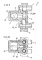
- the module 3 of FIG. 1 differs from module 2 by the fact that its intermediate stage 6, if it is identical to stage 5 as regards its part located in alignment axial with stages 4 and 8, has a large lateral extension 7, of parallelepipedal shape, provided with a removable inspection cover 41, and containing a surge arrester 42.
- the surge arrester, or surge arrester 42 has its two terminals 43, 44 plugged into the aligned slots, respectively upper and lower, of the elements 28.18 for the first terminal 43 and 29.19 for the second terminal 44, and has its earth terminal 45 coming to bear firmly against the body of the screw 10.
- the housing 7 containing the arrester 42 is integrally molded with the body of the intermediate half-sleeve 6.
- this housing 7 can be independent of the body 6, and it is detachably plugged into this body 6 for example by the terminals 43, 44, and possibly 45, or else the housing 7 does not exist at all and it is the arrester itself which is detachably plugged onto this body 6 by means of the terminals 43,44, and possibly 45.
Landscapes
- Insulating Bodies (AREA)
- Emergency Protection Circuit Devices (AREA)
- Elimination Of Static Electricity (AREA)
- Contacts (AREA)
- Coupling Device And Connection With Printed Circuit (AREA)
- Manufacturing Of Electrical Connectors (AREA)
- Mechanical Coupling Of Light Guides (AREA)
- Branch Pipes, Bends, And The Like (AREA)
Applications Claiming Priority (2)
| Application Number | Priority Date | Filing Date | Title |
|---|---|---|---|
| FR868606724A FR2598561B2 (fr) | 1986-05-06 | 1986-05-06 | Dispositif de connexion autodenudant |
| FR8606724 | 1986-05-06 |
Publications (2)
| Publication Number | Publication Date |
|---|---|
| EP0248743A1 EP0248743A1 (fr) | 1987-12-09 |
| EP0248743B1 true EP0248743B1 (fr) | 1991-10-02 |
Family
ID=9335089
Family Applications (1)
| Application Number | Title | Priority Date | Filing Date |
|---|---|---|---|
| EP87420120A Expired - Lifetime EP0248743B1 (fr) | 1986-05-06 | 1987-05-05 | Dispositif de connexion autodénudant |
Country Status (9)
| Country | Link |
|---|---|
| US (2) | US4767354A (no) |
| EP (1) | EP0248743B1 (no) |
| KR (1) | KR950004364B1 (no) |
| CA (1) | CA1299688C (no) |
| DE (1) | DE3773433D1 (no) |
| ES (1) | ES2026561T3 (no) |
| FR (1) | FR2598561B2 (no) |
| IE (1) | IE59667B1 (no) |
| NO (1) | NO169686C (no) |
Families Citing this family (22)
| Publication number | Priority date | Publication date | Assignee | Title |
|---|---|---|---|---|
| DE3902575C1 (no) * | 1989-01-26 | 1990-03-29 | Krone Ag, 1000 Berlin, De | |
| ES2066235T3 (es) * | 1990-03-13 | 1995-03-01 | Krone Ag | Regleta de terminales para la tecnica de la telecomunicacion y de los datos. |
| FR2661565B1 (fr) * | 1990-04-26 | 1992-07-10 | Sofycom | Procede de fabrication d'une fiche fendue tubulaire autodenudante pour dispositif de connexion telephonique. |
| USRE35476E (en) * | 1990-04-27 | 1997-03-11 | Raychem Corporation | Electrical connector block |
| US5096437A (en) * | 1990-04-27 | 1992-03-17 | Thomas & Betts Corporation | Electrical connector block |
| CN1035707C (zh) * | 1990-05-25 | 1997-08-20 | 索菲康姆公司 | 用于快速连接电话线的装置 |
| US5007855A (en) * | 1990-06-20 | 1991-04-16 | The Toro Company | Cable connector |
| US6302723B1 (en) * | 1991-10-11 | 2001-10-16 | Tyco Electronics Corporation | Telecommunications terminal block |
| GB9302586D0 (en) | 1993-02-10 | 1993-03-24 | Egerton A C Ltd | Transmission line connectors and assemblies thereof |
| FR2707446B1 (fr) * | 1993-07-07 | 1995-08-11 | Pouyet Int | Dispositif terminal d'interconnexion téléphonique d'abonné. |
| US5385482A (en) * | 1993-09-01 | 1995-01-31 | Georgian Art Lighting Designs, Inc. | Wiring connector device |
| DE69522639T2 (de) | 1995-09-22 | 2002-04-18 | Pouyet International, Ivry Sur Seine | Test und Trennanordnung für eine Telefonlinie |
| FR2749404B3 (fr) * | 1996-05-29 | 1998-04-17 | Plymouth Francaise Sa | Dispositif de detection d'ouvrages enterres |
| US5704801A (en) * | 1996-08-30 | 1998-01-06 | The Whitaker Corporation | Power cable tap connector |
| WO1998045896A1 (en) * | 1997-04-10 | 1998-10-15 | The Whitaker Corporation | Power cable tap connector |
| US6232557B1 (en) | 1997-11-07 | 2001-05-15 | Rockwell Technologies, Llc | Network cable and modular connection for such a cable |
| US6179644B1 (en) | 1997-11-07 | 2001-01-30 | Rockwell Technologies, Llc | Power and data network system media architecture |
| US6095867A (en) * | 1998-09-21 | 2000-08-01 | Rockwell Technologies, Llc | Method and apparatus for transmitting power and data signals via a network connector system including integral power capacitors |
| DE20200973U1 (de) * | 2002-01-24 | 2003-05-28 | Weidmüller Interface GmbH & Co., 32760 Detmold | Anschlußklemmenleiste |
| ITMI20070017A1 (it) * | 2007-01-08 | 2008-07-09 | Bticino Spa | Dispositivo di connessione rapida a perforazione di isolante per collegamenti elettrici |
| DE102008013317B4 (de) * | 2008-03-10 | 2010-10-14 | Adc Gmbh | Verfahren zur Herstellung einer Aderanschlussleiste mit Gelfüllung |
| US7985094B2 (en) * | 2008-09-15 | 2011-07-26 | Adc Gmbh | Connector block |
Family Cites Families (10)
| Publication number | Priority date | Publication date | Assignee | Title |
|---|---|---|---|---|
| US2033199A (en) * | 1934-06-22 | 1936-03-10 | Burndy Engineering Co Inc | Insulated electrical connecter |
| US2758280A (en) * | 1952-05-29 | 1956-08-07 | Rca Corp | Electrical connector |
| US2710949A (en) * | 1952-09-10 | 1955-06-14 | Singer Mfg Co | Electrical plug connectors and sockets therefor |
| US3945705A (en) * | 1972-06-09 | 1976-03-23 | Minnesota Mining And Manufacturing Company | Wire-splicing apparatus and contact element therefor |
| US3935637A (en) * | 1974-11-26 | 1976-02-03 | Amp Incorporated | Removable wiring device assembly |
| US4080034A (en) * | 1976-06-10 | 1978-03-21 | Amp Incorporated | Insulation piercing tap assembly |
| US4262985A (en) * | 1979-03-26 | 1981-04-21 | Bell Telephone Laboratories, Incorporated | Connector for plural conductors |
| US4449777A (en) * | 1982-03-01 | 1984-05-22 | Minnesota Mining And Manufacturing Company | Drop wire connector |
| FR2541049B1 (fr) * | 1983-02-15 | 1985-09-13 | Faucigny Communication | Dispositif de connexion autodenudant |
| US4684196A (en) * | 1986-04-25 | 1987-08-04 | Kupler Corporation | Electrical clamp connector |
-
1986
- 1986-05-06 FR FR868606724A patent/FR2598561B2/fr not_active Expired
-
1987
- 1987-04-23 IE IE106487A patent/IE59667B1/en not_active IP Right Cessation
- 1987-04-27 KR KR1019870004055A patent/KR950004364B1/ko not_active Expired - Lifetime
- 1987-05-05 ES ES198787420120T patent/ES2026561T3/es not_active Expired - Lifetime
- 1987-05-05 NO NO871863A patent/NO169686C/no not_active IP Right Cessation
- 1987-05-05 DE DE8787420120T patent/DE3773433D1/de not_active Expired - Lifetime
- 1987-05-05 CA CA000536349A patent/CA1299688C/fr not_active Expired - Lifetime
- 1987-05-05 EP EP87420120A patent/EP0248743B1/fr not_active Expired - Lifetime
- 1987-05-06 US US07/047,339 patent/US4767354A/en not_active Ceased
-
1990
- 1990-08-20 US US07/569,951 patent/USRE33903E/en not_active Expired - Lifetime
Also Published As
| Publication number | Publication date |
|---|---|
| FR2598561B2 (fr) | 1989-05-19 |
| NO169686C (no) | 1992-07-22 |
| CA1299688C (fr) | 1992-04-28 |
| IE871064L (en) | 1987-11-06 |
| KR950004364B1 (ko) | 1995-04-28 |
| US4767354A (en) | 1988-08-30 |
| NO871863L (no) | 1987-11-09 |
| NO871863D0 (no) | 1987-05-05 |
| EP0248743A1 (fr) | 1987-12-09 |
| KR880013268A (ko) | 1988-11-30 |
| USRE33903E (en) | 1992-04-28 |
| IE59667B1 (en) | 1994-03-09 |
| DE3773433D1 (de) | 1991-11-07 |
| FR2598561A2 (fr) | 1987-11-13 |
| NO169686B (no) | 1992-04-13 |
| ES2026561T3 (es) | 1992-05-01 |
Similar Documents
| Publication | Publication Date | Title |
|---|---|---|
| EP0248743B1 (fr) | Dispositif de connexion autodénudant | |
| EP0519812B2 (fr) | Connecteur coaxial pour le raccordement d'un câble coaxial à une carte imprimée de circuit électronique | |
| FR2768862A1 (fr) | Prise de courant faible a capuchon arriere organisateur | |
| EP0504035A2 (fr) | Dispositif de raccordement pour un ou deux câbles électriques, et procédé pour monter ce dispositif à l'extrémité du ou des câbles | |
| FR2463526A1 (fr) | Connecteur de cable a armure metallique sous gaine | |
| EP0637853B1 (fr) | Module d'interconnexion rapide de deux lignes téléphoniques monopolaires | |
| FR2745662A1 (fr) | Connecteur telephonique | |
| EP0858136B1 (fr) | Dispositif de connexion électrique à sécurité de contact améliorée | |
| EP2028737B1 (fr) | Dispositif de raccordement électrique entre deux cellules à moyenne ou haute tension et poste de distribution comportant au moins un tel dispositif | |
| EP0466528B1 (fr) | Dispositif de connexion rapide pour une borne de batterie d'accumulateur | |
| EP3089295B1 (fr) | Dispositif d'interconnexion électrique configuré pour établir une liaison équipotentielle entre un tronçon de chemin de câbles et un tronçon de câble électrique | |
| FR2766628A1 (fr) | Peigne d'interconnexion pour alignement de bornes de raccordement electrique d'un appareillage et module(s) de logement d'appareillage correspondant(s) | |
| EP1147574B1 (fr) | Dispositif de connexion pour cable coaxial | |
| EP0642138A1 (fr) | Câble plat comportant au moins deux conducteurs enrobés dans une gaine isolante | |
| FR2702097A1 (fr) | Assemblage de connecteurs électriques, borne électrique d'une seule pièce et connecteur électrique. | |
| EP0933856B1 (fr) | Manchon d'étanchéité rétractable à froid pour câble électrique | |
| FR2963488A1 (fr) | Embout multipolaire de connexion electrique | |
| FR2692724A1 (fr) | Connecteur de fils. | |
| EP3975353A1 (fr) | Dispositif de distribution électrique | |
| EP1928058B1 (fr) | Borne de connexion électrique automatique | |
| FR2527015A1 (fr) | Connecteur verrouillable et deverrouillable pour cables electriques | |
| FR2611341A1 (fr) | Dispositif pour la distribution automatique d'embouts pour cables conducteurs electriques | |
| EP4154360B1 (fr) | Dispositif de detrompage ameliore, ensemble de connexion electrique comportant ledit dispositif de detrompage ameliore et procédé de montage associé | |
| EP0172779A1 (fr) | Connecteur electrique multipolaire | |
| FR2751482A1 (fr) | Dispositif pour la realisation d'une epissure |
Legal Events
| Date | Code | Title | Description |
|---|---|---|---|
| PUAI | Public reference made under article 153(3) epc to a published international application that has entered the european phase |
Free format text: ORIGINAL CODE: 0009012 |
|
| AK | Designated contracting states |
Kind code of ref document: A1 Designated state(s): BE DE ES GB IT NL SE |
|
| 17P | Request for examination filed |
Effective date: 19880129 |
|
| 17Q | First examination report despatched |
Effective date: 19900911 |
|
| GRAA | (expected) grant |
Free format text: ORIGINAL CODE: 0009210 |
|
| AK | Designated contracting states |
Kind code of ref document: B1 Designated state(s): BE DE ES GB IT NL SE |
|
| ITF | It: translation for a ep patent filed | ||
| REF | Corresponds to: |
Ref document number: 3773433 Country of ref document: DE Date of ref document: 19911107 |
|
| GBT | Gb: translation of ep patent filed (gb section 77(6)(a)/1977) | ||
| REG | Reference to a national code |
Ref country code: ES Ref legal event code: FG2A Ref document number: 2026561 Country of ref document: ES Kind code of ref document: T3 |
|
| PLBE | No opposition filed within time limit |
Free format text: ORIGINAL CODE: 0009261 |
|
| STAA | Information on the status of an ep patent application or granted ep patent |
Free format text: STATUS: NO OPPOSITION FILED WITHIN TIME LIMIT |
|
| 26N | No opposition filed | ||
| EAL | Se: european patent in force in sweden |
Ref document number: 87420120.5 |
|
| REG | Reference to a national code |
Ref country code: GB Ref legal event code: IF02 |
|
| PGFP | Annual fee paid to national office [announced via postgrant information from national office to epo] |
Ref country code: NL Payment date: 20040416 Year of fee payment: 18 |
|
| PGFP | Annual fee paid to national office [announced via postgrant information from national office to epo] |
Ref country code: SE Payment date: 20040521 Year of fee payment: 18 |
|
| PG25 | Lapsed in a contracting state [announced via postgrant information from national office to epo] |
Ref country code: SE Free format text: LAPSE BECAUSE OF NON-PAYMENT OF DUE FEES Effective date: 20050506 |
|
| PG25 | Lapsed in a contracting state [announced via postgrant information from national office to epo] |
Ref country code: NL Free format text: LAPSE BECAUSE OF NON-PAYMENT OF DUE FEES Effective date: 20051201 |
|
| EUG | Se: european patent has lapsed | ||
| NLV4 | Nl: lapsed or anulled due to non-payment of the annual fee |
Effective date: 20051201 |
|
| PGFP | Annual fee paid to national office [announced via postgrant information from national office to epo] |
Ref country code: GB Payment date: 20060525 Year of fee payment: 20 |
|
| PGFP | Annual fee paid to national office [announced via postgrant information from national office to epo] |
Ref country code: ES Payment date: 20060526 Year of fee payment: 20 |
|
| PGFP | Annual fee paid to national office [announced via postgrant information from national office to epo] |
Ref country code: IT Payment date: 20060531 Year of fee payment: 20 |
|
| PGFP | Annual fee paid to national office [announced via postgrant information from national office to epo] |
Ref country code: BE Payment date: 20060620 Year of fee payment: 20 |
|
| PGFP | Annual fee paid to national office [announced via postgrant information from national office to epo] |
Ref country code: DE Payment date: 20060630 Year of fee payment: 20 |
|
| PG25 | Lapsed in a contracting state [announced via postgrant information from national office to epo] |
Ref country code: ES Free format text: LAPSE BECAUSE OF EXPIRATION OF PROTECTION Effective date: 20070507 |
|
| REG | Reference to a national code |
Ref country code: GB Ref legal event code: PE20 |
|
| REG | Reference to a national code |
Ref country code: ES Ref legal event code: FD2A Effective date: 20070507 |
|
| PG25 | Lapsed in a contracting state [announced via postgrant information from national office to epo] |
Ref country code: GB Free format text: LAPSE BECAUSE OF EXPIRATION OF PROTECTION Effective date: 20070504 |
|
| BE20 | Be: patent expired |
Owner name: *CARPANO & PONS Effective date: 20070505 |