EP0248733A1 - Beschickungsvorrichtung für Ionenaustauscher-Harze - Google Patents
Beschickungsvorrichtung für Ionenaustauscher-Harze Download PDFInfo
- Publication number
- EP0248733A1 EP0248733A1 EP87401240A EP87401240A EP0248733A1 EP 0248733 A1 EP0248733 A1 EP 0248733A1 EP 87401240 A EP87401240 A EP 87401240A EP 87401240 A EP87401240 A EP 87401240A EP 0248733 A1 EP0248733 A1 EP 0248733A1
- Authority
- EP
- European Patent Office
- Prior art keywords
- hopper
- loading
- chamber
- outlet tube
- resin
- Prior art date
- Legal status (The legal status is an assumption and is not a legal conclusion. Google has not performed a legal analysis and makes no representation as to the accuracy of the status listed.)
- Withdrawn
Links
- 239000003456 ion exchange resin Substances 0.000 title description 2
- 229920003303 ion-exchange polymer Polymers 0.000 title description 2
- 239000011347 resin Substances 0.000 claims abstract description 39
- 229920005989 resin Polymers 0.000 claims abstract description 39
- 150000002500 ions Chemical class 0.000 claims description 17
- 239000012530 fluid Substances 0.000 description 10
- XLYOFNOQVPJJNP-UHFFFAOYSA-N water Substances O XLYOFNOQVPJJNP-UHFFFAOYSA-N 0.000 description 6
- 230000002285 radioactive effect Effects 0.000 description 3
- 239000000654 additive Substances 0.000 description 2
- 230000015572 biosynthetic process Effects 0.000 description 2
- 125000002091 cationic group Chemical group 0.000 description 2
- 230000005484 gravity Effects 0.000 description 2
- 230000005855 radiation Effects 0.000 description 2
- 238000007789 sealing Methods 0.000 description 2
- 239000000126 substance Substances 0.000 description 2
- 239000004952 Polyamide Substances 0.000 description 1
- 125000000129 anionic group Chemical group 0.000 description 1
- KGBXLFKZBHKPEV-UHFFFAOYSA-N boric acid Chemical compound OB(O)O KGBXLFKZBHKPEV-UHFFFAOYSA-N 0.000 description 1
- 239000004327 boric acid Substances 0.000 description 1
- 230000007797 corrosion Effects 0.000 description 1
- 238000005260 corrosion Methods 0.000 description 1
- 238000010790 dilution Methods 0.000 description 1
- 239000012895 dilution Substances 0.000 description 1
- 238000011010 flushing procedure Methods 0.000 description 1
- 239000013529 heat transfer fluid Substances 0.000 description 1
- 238000003780 insertion Methods 0.000 description 1
- 230000037431 insertion Effects 0.000 description 1
- 238000009413 insulation Methods 0.000 description 1
- 239000007788 liquid Substances 0.000 description 1
- 239000000463 material Substances 0.000 description 1
- 229920002647 polyamide Polymers 0.000 description 1
- 238000012958 reprocessing Methods 0.000 description 1
- 230000000717 retained effect Effects 0.000 description 1
- 229920006395 saturated elastomer Polymers 0.000 description 1
- 239000000243 solution Substances 0.000 description 1
- 239000000725 suspension Substances 0.000 description 1
Images
Classifications
-
- B—PERFORMING OPERATIONS; TRANSPORTING
- B01—PHYSICAL OR CHEMICAL PROCESSES OR APPARATUS IN GENERAL
- B01J—CHEMICAL OR PHYSICAL PROCESSES, e.g. CATALYSIS OR COLLOID CHEMISTRY; THEIR RELEVANT APPARATUS
- B01J47/00—Ion-exchange processes in general; Apparatus therefor
- B01J47/10—Ion-exchange processes in general; Apparatus therefor with moving ion-exchange material; with ion-exchange material in suspension or in fluidised-bed form
-
- B—PERFORMING OPERATIONS; TRANSPORTING
- B01—PHYSICAL OR CHEMICAL PROCESSES OR APPARATUS IN GENERAL
- B01J—CHEMICAL OR PHYSICAL PROCESSES, e.g. CATALYSIS OR COLLOID CHEMISTRY; THEIR RELEVANT APPARATUS
- B01J47/00—Ion-exchange processes in general; Apparatus therefor
-
- B—PERFORMING OPERATIONS; TRANSPORTING
- B01—PHYSICAL OR CHEMICAL PROCESSES OR APPARATUS IN GENERAL
- B01J—CHEMICAL OR PHYSICAL PROCESSES, e.g. CATALYSIS OR COLLOID CHEMISTRY; THEIR RELEVANT APPARATUS
- B01J8/00—Chemical or physical processes in general, conducted in the presence of fluids and solid particles; Apparatus for such processes
- B01J8/0015—Feeding of the particles in the reactor; Evacuation of the particles out of the reactor
Definitions
- the invention relates to a device for loading anioic or cationic resins in ion exchangers used for the treatment of effluents and fluids from the various circuits of a pressurized water nuclear power plant.
- Pressurized water nuclear power plants have many fluid circuits, including the primary circuit.
- the primary fluid which circulates in this circuit has a double function; it acts as a heat transfer fluid intended to extract the calories provided by the chain reaction within the reactor, but also as a moderating fluid in combination with certain additives, more particularly boric acid.
- Another circuit the liquid effluent treatment circuit, purifies all radioactive elements of the effluents which must return to the storage tanks located outside the containment.
- the ion exchanger is provided with a supply duct which is offset from the casemat in which it is enclosed. This duct extends to a height such that its connection flange comes flush with the service floor. A funnel is then screwed onto this flange while the staff manually pours bags of resin into the same funnel. By gravity, the resins, guided in the conduit, accumulate in the ion exchanger.
- the present invention relates to a mechanical loading device of a resin exchanger which overcomes these drawbacks. It allows remote loading of resin ion exchangers from an unexposed area. It therefore makes it possible to prevent the handling personnel from being exposed to radioactive doses.
- the loading device comprises: - a hopper, - a receiving chamber located under the hopper, said chamber comprising an outlet opening to which a discharge chute is connected, and a flexible outlet tube located in the extension of the chute, - first transfer means located in the receiving chamber for transferring said resin to the outlet tube, - Second transfer means located in the outlet tube and over the entire length of the latter, for transferring said resin to a loading funnel of said ion exchanger.
- the loading hopper can be placed at a distance from the ion exchanger, and protected from effective biological protection.
- the first transfer means drive the resins to the flexible tube; then the second transfer means drive them to the loading T of the exchanger.
- the resins then flow into the ion exchanger.
- the exposure time is limited to the time taken by a worker to unclip a shutter tape from a side loading opening, this time being able to be further reduced by the use of a chain connector, to introduce the end of the pipe in the loading T, and to carry out the reverse operations.
- the loading device further comprises a devouting chamber, located between the hopper and the receiving chamber, and in which is disposed a rotating shaft supporting a plurality of arms arranged in a hortogonal fashion.
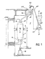
- FIG. 1 shows an elevation view of a resin ion exchanger.
- This exchanger designated by the general reference 1, rests by means of pads 3 on a support 5 linked to the concrete structure 7.
- Different connections are connected to the exchanger.
- a nozzle 9 leading to the upper part of the exchanger makes it possible to introduce the fluid to be treated after the latter has been depressurized and brought to a temperature compatible with the organic products which constitute the resins.
- Two nozzles, 11 and 13, leading to the lower part of the exchanger, allow the continuous evacuation and treatment of this same fluid. Strainers, of the conventional type (not shown), are placed in the nozzles 11 and 13 so that only the fluid can pass, the resins being retained.
- a central tap 15 also located at the lower part of the exchanger is used for emptying the used resins.
- a tap 17 having two bends in opposite directions extends to a connecting flange 19 housed in a recess 21 provided in the slab of the circulation floor.
- the tap 17 allows the exchanger to be fed of ions in new resins.
- the flange 19 is closed by a tape fixed by bolts. Reloading is carried out by means of a funnel (not shown) which is screwed in place of the tape on the flange 19.
- This funnel consists of a vertical cylindrical portion linked to an upper part of cylindrical-frustoconical shape.
- This loading device is screwed manually by direct access into the recess 21 of the circulation floor 23.
- the resins are loaded manually using bags poured into the funnel. The resins flow by gravity into the ion exchanger through the nozzle 17.
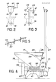
- the invention overcomes this drawback. To this end, it firstly comprises a loading funnel 25 shown in FIG. 1 and more particularly in FIG. 2.
- This funnel permanently fixed to the flange 19, has a lateral tap 27 for the introduction of a flexible pipe 29 preferably terminated by a guide end piece 31.
- the function of the pipe and the end piece, which have been shown in dotted lines in FIG. 2, will be explained later with reference to FIG. 4.
- a T-connector referenced 33, provided with two clamps 35 and 37 and screwed at the bottom on the flange 19.
- a sealing tape 39 closes the upper end, while a sealing tape 41 closes, also hermetically, the lateral insertion orifice 35.
- the tape 41 is fixed on the flange 35 by means of a flexible chain connection 43 rather than bolts, as this is done in a classic way.
- a loading device 45 consists of a hopper 47 which can be closed by a cover 49 pivotally mounted on the hopper.
- the cover 49 is provided with electrical safety contacts 51 which prohibit the control of the gear motor 59 when the cover is not in the correct position.
- a devouting chamber 53 is connected to the lower end of the hopper.
- a shaft 55 mounted rotatably, supporting a plurality of arms 57 (see Figure 5) arranged orthogonally.
- the shaft 55 is rotated by a gearmotor group 59.
- the gearmotor group drives in parallel a first transfer screw, or loading screw 61, located in a receiving chamber placed under the devouting chamber 53.
- the chamber 63 has a outlet opening to which a discharge chute 65 is connected.
- a flexible outlet tube 67 is located in the extension of the chute 65 perpendicular thereto.
- This semi-rigid tube is made for example of polyamide.
- the transfer means 61 are constituted by a helical screw in flat wires, of the Archimedes screw type, the longitudinal axis of which is parallel to the rotating shaft 55. This screw is driven by the same geared motor group 59 as the shaft rotating 55. The transfer screw 61 pours the resin 69 into the chute 65. The resin is then taken up by a transfer spring 71 which is also of the helical type made of flat wires. This spring 71 is present over the entire length of the flexible loading tube 67.
- the entire loading device namely the gearmotor group 59 and the motor 73, is supplied with energy electric and controlled by the control box 75 fixed under the hopper.
- the worker begins by unclamping the shutter tape 41 which closes the lateral opening. This operation is made faster by the use of a chain connector 43 which requires less time to open and close than conventional bolts (see Figure 3).
- the guide piece 31 is then introduced inside T 33 or the funnel 25 ( Figure 2).
- the end of the pipe 67 having been put in place, the loading operation can begin.
- the resins are poured into the hopper 45.
- the rotating arms 57 prevent the formation of agglomerates while the transfer screws 61 and 71 drive the resin balls to the loading T or to the funnel, as the case may be.
- the resins are then poured into the exchanger through the nozzle 17 (see Figure 1).
- the exposure time of a worker to the radiations emitted by the resins is limited to the time necessary for, on the one hand, debriding the shutter tape, introducing the end of the flexible hose and on the other hand remove the end of this hose and replace the tape when the loading has been carried out. Between these two operations, loading can be carried out safely, away from radiation.
Landscapes
- Chemical & Material Sciences (AREA)
- Organic Chemistry (AREA)
- Chemical Kinetics & Catalysis (AREA)
- Processing And Handling Of Plastics And Other Materials For Molding In General (AREA)
- Treatment Of Liquids With Adsorbents In General (AREA)
- Treatment Of Water By Ion Exchange (AREA)
- Feeding, Discharge, Calcimining, Fusing, And Gas-Generation Devices (AREA)
- Filling Or Emptying Of Bunkers, Hoppers, And Tanks (AREA)
Applications Claiming Priority (2)
| Application Number | Priority Date | Filing Date | Title |
|---|---|---|---|
| FR8608063 | 1986-06-04 | ||
| FR8608063A FR2599641B1 (fr) | 1986-06-04 | 1986-06-04 | Dispositif de chargement de resines echangeuses d'ions |
Publications (1)
| Publication Number | Publication Date |
|---|---|
| EP0248733A1 true EP0248733A1 (de) | 1987-12-09 |
Family
ID=9336001
Family Applications (1)
| Application Number | Title | Priority Date | Filing Date |
|---|---|---|---|
| EP87401240A Withdrawn EP0248733A1 (de) | 1986-06-04 | 1987-06-03 | Beschickungsvorrichtung für Ionenaustauscher-Harze |
Country Status (8)
| Country | Link |
|---|---|
| EP (1) | EP0248733A1 (de) |
| JP (1) | JPS62298459A (de) |
| KR (1) | KR880000143A (de) |
| CA (1) | CA1278269C (de) |
| DE (1) | DE248733T1 (de) |
| ES (1) | ES2001001A4 (de) |
| FR (1) | FR2599641B1 (de) |
| ZA (1) | ZA873924B (de) |
Citations (2)
| Publication number | Priority date | Publication date | Assignee | Title |
|---|---|---|---|---|
| FR2312437A1 (fr) * | 1975-05-28 | 1976-12-24 | Milton Roy Dosapro | Procede pour le reglage du debit de transporteurs-doseurs de matieres granuleuses ou pulverulentes |
| FR2478045A3 (fr) * | 1980-03-14 | 1981-09-18 | Libra Sa | Dispositif a vis transporteuse pour l'alimentation de vis transporteuses verticales |
Family Cites Families (1)
| Publication number | Priority date | Publication date | Assignee | Title |
|---|---|---|---|---|
| JPS60137713A (ja) * | 1983-12-24 | 1985-07-22 | Ichieda Sangyo Kk | 定量移送装置 |
-
1986
- 1986-06-04 FR FR8608063A patent/FR2599641B1/fr not_active Expired
-
1987
- 1987-05-26 CA CA000537993A patent/CA1278269C/en not_active Expired - Lifetime
- 1987-06-02 JP JP62138843A patent/JPS62298459A/ja active Pending
- 1987-06-02 ZA ZA873924A patent/ZA873924B/xx unknown
- 1987-06-03 ES ES87401240T patent/ES2001001A4/es active Pending
- 1987-06-03 DE DE198787401240T patent/DE248733T1/de active Pending
- 1987-06-03 EP EP87401240A patent/EP0248733A1/de not_active Withdrawn
- 1987-06-03 KR KR870005610A patent/KR880000143A/ko not_active Withdrawn
Patent Citations (2)
| Publication number | Priority date | Publication date | Assignee | Title |
|---|---|---|---|---|
| FR2312437A1 (fr) * | 1975-05-28 | 1976-12-24 | Milton Roy Dosapro | Procede pour le reglage du debit de transporteurs-doseurs de matieres granuleuses ou pulverulentes |
| FR2478045A3 (fr) * | 1980-03-14 | 1981-09-18 | Libra Sa | Dispositif a vis transporteuse pour l'alimentation de vis transporteuses verticales |
Non-Patent Citations (1)
| Title |
|---|
| PATENT ABSTRACTS OF JAPAN, vol. 9, no. 300 (M-433)[2023], 27 novembre 1985; & JP-A-60 137 713 (ICHIEDA SANGYO K.K.) 22-07-1985 * |
Also Published As
| Publication number | Publication date |
|---|---|
| ES2001001A4 (es) | 1988-04-16 |
| KR880000143A (ko) | 1988-03-23 |
| JPS62298459A (ja) | 1987-12-25 |
| DE248733T1 (de) | 1988-06-09 |
| FR2599641B1 (fr) | 1988-08-05 |
| ZA873924B (en) | 1987-12-02 |
| CA1278269C (en) | 1990-12-27 |
| FR2599641A1 (fr) | 1987-12-11 |
Similar Documents
| Publication | Publication Date | Title |
|---|---|---|
| EP0537071B1 (de) | Verfahren zur Konditionierung oder Wiederaufbereitung von gebrauchten ionischen Kartuschen | |
| BE897468A (fr) | Procede de remplacement des broches de guidage d'un tube-guide et dispositif correspondant | |
| FR2672100A1 (fr) | Vanne de coupure automatique a deux etages. | |
| EP0004241A1 (de) | Verbindungseinrichtung zwischen einem Behälter und einem zu entladenden Raum | |
| EP0248733A1 (de) | Beschickungsvorrichtung für Ionenaustauscher-Harze | |
| EP0153225B1 (de) | Wärmetauscher mit einem Notkühlsystem und schneller Kernreaktor mit einem derartigen Wärmetauscher | |
| EP0148802B1 (de) | Einrichtung zur Handhabung von Brennstoffelementen und Brennstoffelement für die Vorrichtung | |
| FR2728382A1 (fr) | Procede pour demonter des elements encombrants des equipements internes d'une cuve sous pression d'une installation nucleaire et pour recueillir les elements demontes | |
| FR2783345A1 (fr) | Procede et installation de remplissage de futs contenant des dechets dangereux | |
| FR2525379A1 (fr) | Dispositif d'irradiation pour exposer des matieres a irradier au coeur d'un reacteur nucleaire | |
| CA1249509A (fr) | Appareil d'intervention sur un robinet immerge | |
| EP0555127B1 (de) | Verfahren und Einrichtung zur Dekontaminierung eines gebrauchten nuklearen Dampferzeugers | |
| EP0437394B1 (de) | Rührerantreibungseinheit, insbesondere ein MischerDekantierapparat zur Verwendung in einer Vorrichtung zur Wiederaufarbeitung von Kernbrennstoffen | |
| EP0018262A1 (de) | Schneller Kernreaktor mit einem zylindrischen Innenbehälter | |
| EP1700315A2 (de) | Einrichtung und verfahren zur packung von kernbrennstoffbaugruppen mit doppel-eingrenzungsbarriere | |
| FR2953319A1 (fr) | Dispositif et procede d'assistance au chargement et dechargement du coeur d'un reacteur nucleaire a caloporteur sodium et reacteur nucleaire a caloporteur sodium comprenant un tel dispositif | |
| EP0022032B1 (de) | Vorrichtung und Verfahren zum Ausführen von Austauschreaktionen in Lagerbecken für radioaktive Stoffe | |
| EP0175615A1 (de) | Bewegliche Mischvorrichtung | |
| EP0819310B1 (de) | Vorrichtung zur rückhaltung von ferromagnetischen teilchen in einer flüssigkeit, die in einer leitung fliesst | |
| FR2792346A1 (fr) | Chasse automatique pour eaux usees | |
| EP0030884A1 (de) | Vorrichtung zum Behandeln der Verbindungen in einer Flüssigkeit | |
| EP0048671B1 (de) | Anlage zur Energieerzeugung mit mehreren Kernreaktoren mit schnellen Neutronen und mit einer Vorrichtung zum Auswechseln von Brennelementen | |
| EP0203861A1 (de) | Modulare Ultrafiltrationsvorrichtung für die Kühlflüssigkeit eines Kernreaktors | |
| FR2520150A1 (fr) | Dispositif pour transferer horizontalement entre deux enceintes des elements combustibles nucleaires stockes en position verticale | |
| EP0247937B1 (de) | Ladeeinrichtung für spaltzonenbildende Elemente eines Kernreaktors mit schnellen Neutronen |
Legal Events
| Date | Code | Title | Description |
|---|---|---|---|
| PUAI | Public reference made under article 153(3) epc to a published international application that has entered the european phase |
Free format text: ORIGINAL CODE: 0009012 |
|
| AK | Designated contracting states |
Kind code of ref document: A1 Designated state(s): BE CH DE ES GB LI |
|
| GBC | Gb: translation of claims filed (gb section 78(7)/1977) | ||
| DET | De: translation of patent claims | ||
| 17P | Request for examination filed |
Effective date: 19880516 |
|
| 17Q | First examination report despatched |
Effective date: 19890331 |
|
| STAA | Information on the status of an ep patent application or granted ep patent |
Free format text: STATUS: THE APPLICATION IS DEEMED TO BE WITHDRAWN |
|
| 18D | Application deemed to be withdrawn |
Effective date: 19920208 |
|
| RIN1 | Information on inventor provided before grant (corrected) |
Inventor name: LAVALERIE, CLAUDE |