EP0248464A1 - Vorrichtung zum Verpacken einer Reihe von Deckeln - Google Patents
Vorrichtung zum Verpacken einer Reihe von Deckeln Download PDFInfo
- Publication number
- EP0248464A1 EP0248464A1 EP87200897A EP87200897A EP0248464A1 EP 0248464 A1 EP0248464 A1 EP 0248464A1 EP 87200897 A EP87200897 A EP 87200897A EP 87200897 A EP87200897 A EP 87200897A EP 0248464 A1 EP0248464 A1 EP 0248464A1
- Authority
- EP
- European Patent Office
- Prior art keywords
- row
- covers
- packaging
- station
- packaging material
- Prior art date
- Legal status (The legal status is an assumption and is not a legal conclusion. Google has not performed a legal analysis and makes no representation as to the accuracy of the status listed.)
- Granted
Links
- 238000004806 packaging method and process Methods 0.000 title claims abstract description 57
- 239000000853 adhesive Substances 0.000 claims abstract description 59
- 230000001070 adhesive effect Effects 0.000 claims abstract description 59
- 239000005022 packaging material Substances 0.000 claims abstract description 32
- 230000032258 transport Effects 0.000 claims description 4
- 239000002390 adhesive tape Substances 0.000 description 5
- 230000001419 dependent effect Effects 0.000 description 4
- 238000006073 displacement reaction Methods 0.000 description 4
- 230000015572 biosynthetic process Effects 0.000 description 3
- 238000011144 upstream manufacturing Methods 0.000 description 3
- 238000002844 melting Methods 0.000 description 2
- 230000008018 melting Effects 0.000 description 2
- 230000001105 regulatory effect Effects 0.000 description 2
- 238000010276 construction Methods 0.000 description 1
- 238000001514 detection method Methods 0.000 description 1
- 230000002349 favourable effect Effects 0.000 description 1
- 239000003292 glue Substances 0.000 description 1
- 238000010438 heat treatment Methods 0.000 description 1
- 238000004519 manufacturing process Methods 0.000 description 1
- 239000000463 material Substances 0.000 description 1
- 238000000034 method Methods 0.000 description 1
- 238000012856 packing Methods 0.000 description 1
- 238000005192 partition Methods 0.000 description 1
- 230000003252 repetitive effect Effects 0.000 description 1
- 238000007493 shaping process Methods 0.000 description 1
- 230000001360 synchronised effect Effects 0.000 description 1
- 230000000007 visual effect Effects 0.000 description 1
Images


Classifications
-
- B—PERFORMING OPERATIONS; TRANSPORTING
- B65—CONVEYING; PACKING; STORING; HANDLING THIN OR FILAMENTARY MATERIAL
- B65B—MACHINES, APPARATUS OR DEVICES FOR, OR METHODS OF, PACKAGING ARTICLES OR MATERIALS; UNPACKING
- B65B11/00—Wrapping, e.g. partially or wholly enclosing, articles or quantities of material, in strips, sheets or blanks, of flexible material
- B65B11/06—Wrapping articles, or quantities of material, by conveying wrapper and contents in common defined paths
- B65B11/08—Wrapping articles, or quantities of material, by conveying wrapper and contents in common defined paths in a single straight path
- B65B11/10—Wrapping articles, or quantities of material, by conveying wrapper and contents in common defined paths in a single straight path to fold the wrappers in tubular form about contents
- B65B11/12—Wrapping articles, or quantities of material, by conveying wrapper and contents in common defined paths in a single straight path to fold the wrappers in tubular form about contents and then to form closing folds of similar form at opposite ends of the tube
-
- B—PERFORMING OPERATIONS; TRANSPORTING
- B65—CONVEYING; PACKING; STORING; HANDLING THIN OR FILAMENTARY MATERIAL
- B65D—CONTAINERS FOR STORAGE OR TRANSPORT OF ARTICLES OR MATERIALS, e.g. BAGS, BARRELS, BOTTLES, BOXES, CANS, CARTONS, CRATES, DRUMS, JARS, TANKS, HOPPERS, FORWARDING CONTAINERS; ACCESSORIES, CLOSURES, OR FITTINGS THEREFOR; PACKAGING ELEMENTS; PACKAGES
- B65D75/00—Packages comprising articles or materials partially or wholly enclosed in strips, sheets, blanks, tubes or webs of flexible sheet material, e.g. in folded wrappers
- B65D75/04—Articles or materials wholly enclosed in single sheets or wrapper blanks
- B65D75/06—Articles or materials wholly enclosed in single sheets or wrapper blanks in sheets or blanks initially folded to form tubes
- B65D75/08—Articles or materials wholly enclosed in single sheets or wrapper blanks in sheets or blanks initially folded to form tubes with the ends of the tube closed by folding
Definitions
- the invention relates to a device of the type referred to in the preamble of claim 1 for packaging a row of covers positioned coaxially of one another.
- a device is des.cr- ibed in the earlier but not pre-published Dutch patent application 85.01520.
- this device it is possible to package a row of covers, whereby the packaging material is arranged tightly around the row. From this results a robust, form retaining packaging.
- a limitation of this device is the maximum permissible difference from one another of the row lengths of covers of at most 20 mm.
- the invention has for its object to provide a device for packaging a row of covers whereby the covers are packaged into a sack while the covers can easily be poured from the sack via the discharge opening. Packing in a sack affords the further advantage that due to a relatively greater length of the discharge opening flap there is greater tolerance for cover row lengths to be handled.
- the folding station comprises gripping means gripping onto the wrapped packaging material from outside, which means hold the packaging material away from the row of covers during forming of the longitudinal fold. In this way there results extra space in the paper that is wrapped and affixed around the row of covers.
- Extra space can be provided in the paper in a simple manner if the gripping means grip the longitudinal fold edge which extends from the base plate and/or the locking plate, since these longitudinal fold edges extend freely from the base and/or locking plate and no opposing forces have to be overcome in the forming of the space.
- a particularly advantageous embodiment of the gripping means results if gripping takes place by suction attachment to the packaging material, as a pressure difference is applied crosswise of the packaging material, and for this purpose the gripping means are connected via a line to a vacuum source and attach themselves by suction via at least one vacuum nozzle to the packaging material.
- the gripping means are accommodated in the base plate and/or locking plate and the gripping means comprise at least one vacuum nozzle it is recommended that the base plate and/or the locking plate comprises an underpressure chamber of which a wall facing toward the packaging material is provided with the vacuum nozzle.
- the longitudinal fold edges located in the discharge opening flap are also adhered to each other so that the sack opening is adhered up to the discharge opening and discharge can take place without risk.
- a support is temporarily arranged at that place such that the longitudinal fold edges to be adhered to each other can be pressed against it, ensuring glue adhesion.
- the device is further characterized by an adhesive support which can move axially reciprocating relative to a row of covers present in the folding/adhesive station and accommodated in a sheet of packaging material and which forms a support for the longitudinal fold edges to be adhered.
- a con- ,striction in the packaging be formed in the proximity of this cover.
- a constriction can be effected if the adhesive support can move to a position P at an interval p from the row of covers, and if the adhesive support takes the form of a cylinder, the section of which corresponds substantially with that of the row of covers and is provided with means for generating an underpressure in the space lying between the row of covers and the adhesive support, as a result of which a packaging constriction is formed.
- the adhesive support can move from the position P to the position Q close to the end wall position of the row of covers.
- the movement of the adhesive support can be regulated with certainty if the adhesive support is provided with a sensor for setting the distances P and Q.
- the tolerance for row lengths to be handled is already increased.
- the tolerance can be increased still further if the folding means for folding and folding back of the discharge opening flap are located at a quite large interval beyond the end folding means for forming the sack bottom, and after forming of the sack bottom the virtually completed packaging is moved using a pusher element to the end folding unit for formation of the discharge opening flap.
- the folding station comprises:
- the device according to the invention permits a greater tolerance for row length, it is possible to handle counted off quantities of covers with this device, and to this end the device is further characterized in that the feed station comprises a counting unit for forming a row of covers consisting of a determined set number.
- the invention relates to a row of covers packaged with the device according to the invention which are accommodated in a sack-shaped packaging which is provided on one side with a closed bottom and on the other with a discharge opening for opening which is folded back and may be adhered to the packaging.
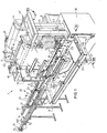
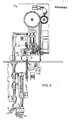
- the device 1 comprises successively in the packaging direction: a feed station A for the rows of covers 2; a wrapping station B for wrapping the row of covers 2 in sheet 3; a folding station C for folding the wrapped sheet 5; and an intermediate station D for adhering fold parts to the packaging.
- device 1 comprises conveyor means 8 for transporting the row 2.
- feed station A and wrapping station B are also a supply station E for widths of packaging material 9.
- cutting unit F present for cutting packaging material 9 into sheet 3.
- Feed station A is provided with two feed units 10 and 11 which have a trough form and are each connected upstream to a machine manufacturing elements 13.
- Each feed unit 10 and 11 leads to a feed table 12 which is guided in guides 14 and 15 and can slide under the influence of a pneumatic cylinder 216 between each of the two feed units 10 and 11 and wrapping station B.
- Conveyor means 8 comprise for each feed unit 10 and 11 a conveyor unit 16 and 17 respectively.
- Each conveyor unit 16 and 17 comprises a guide strip 18 having a strip 19 firmly attached to it downstream and a cut-off member 21 located upstream which can be moved up and down. using a cylinder 20.
- Guide strip 18 is firmly attached to a piston 23 guided in a cylinder 22.
- each trough-shaped feed unit 10, 11 is a known counting unit 160 which counts off the covers by means of light reflection on a cover portion and which after counting a pre-determined number separates this row 2 from the growing row 24, this row 2 then being enclosed between the strips 19 and 21 of the respective conveyor units 16 and 17.
- Conveyor unit 16 transports row 2 at a faster speed relative to the speed of growth of the row 24 to an intermediate station 25 directly at the outlet of each feed unit 10 and 11 or to a point in front of a pusher element 28.
- Regulating, detection, control and actuating means do not per se form part of the invention and are therefore not described further.
- conveyor unit 17 transports the row 2 to a point in front of a pusher element 28 which can move reciprocally over the feed table 12 (see fig. 13).
- Pusher element 28 is guided via a hook-shaped arm 29 by means of guides 30 and 31 on the feed table 12. In this way the pusher element 28 moves when feed table 12 moves.
- a guide 32 arranged along the edge 33 adjoining wrapping station B.
- Guide 32 can tilt between a tilted position shown in fig. 1 and 13 and a position whereby the guide lies in the plane of the feed table. In this latter position the guide partially bridges a slit 34 lying between feed station A and wrapping station B.
- the movement of pusher element 28 away from wrapping station B is bounded by a buffer unit 35 with which the stroke of pusher element 28 is adjustable, also using adjustment bolt 236, subject for example to the diameter of the covers 13.
- Feed table 12 together with its guiding is releasably attached to the base frame 36 of device 1.
- feed station A can be aligned relative to wrapping station B.
- Supply unit 1 for widths of packaging material 9 comprises a tower 39 which is carried on the frame 36.
- Tower 39 comprises a seat 40 for rolls 41 and 44 of packaging material.
- the width 9 is guided over the roller 42 and roller 43, and then guided between a drum roller 45 and a co-operating pressure roller 46.
- Drum roller 45 is provided with an internally fitted motor which drives a shaft 48 coupled via toothed wheels 47 with drum 45.
- a code is applied to width 9 and thereby to the sausage-like packaging 4.
- the code applied is for example a code for the device 1.
- the rollers 45 and 46 are attached for rotation to carriages 50 and 51 guided along tower 39, which carriages, using a spindle 52 screwed into a cross piece 53, are height adjustable in respect of feed table 12 and a work table 54 located in the same plane.
- Each carriage 50 and 51 is provided with a spindle 52.
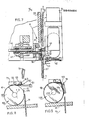
- Fig. 7 shows in more detail the cutting unit F for cutting into a sheet 3 the width of packaging material 9 which is guided between plates 55 and 56 forming a letter box.
- the cut sheet 3 is guided at its longitudinal edges in "U"-shaped guide strips 57.
- the cutting unit consists of a stationary knife blade 58 extending over the whole breadth of the width 9 of packaging material and a disc-shaped knife 59 co-operating with it which can be displaced transversely over the width 9.
- displacement knife 59 is driven for rotation by rollers 61 running over a paper pressure strip 60.
- punches 63 actuated by a pressure cylinder 62 the sheet is clamped in position after cutting.
- the rotary knife 59 is connected for displacement on a pressure cylinder 64 and moves between two positions situated on either side of width 9 (see fig. 1) so that the paper pressure strip 60 can be displaced between the positions shown in fig. 7 with full lines and dashed lines.
- a nose 67 mounted for sliding in the piece 65 by means of a rod 66 can be carried. into the passage between plates 55 and 56, in order to lead the width 9 passing through cutting unit F such that the width goes between the stationary knife 58 and the paper pressure strip 60 and is guided downstream in the side guides 57.
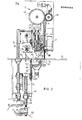
- the figures 2-6, 8 and 9 show in more detail the wrapping station B, the folding station C and a part of the adhesive station D.
- Wrapping station B comprises a wrapping base plate 68 aligned with feed table 12 and a wrapping plate 69 arranged at an interval a above base plate 68. Wrapping plate 69 is suspended while locked against tilting out of the horizontal position from a beam 70 by means of links 71 and 72 in parallelepiped orientation. Link 71 is provided with a nose 73 which co-operates with an adjustable stop 74. A lowest position of wrapping plate 69 is set in this way, and can if required be adjusted with the adjusting screw 275. Springs 161 force the wrapping plate 69 to its lowest position.
- Folding station C comprises a longitudinal fold unit 75 with a folding base plate 76 and a locking plate 77 arranged for tilting at an interval b above base plate 76, and reciprocally co-operating folder blades 78 and 79.
- Folder blade 79 referred to as the lower folder 79, forms the fold edge 80 to be applied against the row 2 and is provided with a wedge-shaped pushing member 81 which is guided for sliding along the surface 82 of the lower folder 79 facing towards the row of covers 2 using a rod 84 mounted for sliding in the bearing 83.
- the lower folder can be moved through a slit 85 arranged in folding base plate 76 using a franc 86 which supports on and rolls over the curve 88 by means of a curve roller 87.
- the lower folder is arranged on the lower folder frame 90 which is guided on rod 89, whereby a spring 91 continually forces frame 90 to its lowest position.
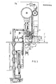
- the figures 3-6 and 8 and 9 show the operation of the wrapping station B and the longitudinal fold unit 75.
- a row 98 is pressed through a hanging sheet 99 and carried beneath the wrapping plate 69. Fingers 127 and 128 of pusher element 28 ' prevent tilting of the covers. The punches 63 are deactivated during this movement.
- the interval a is smaller than the diameter d of the elements 13, so that when row 98 is carried beneath plate 69 the sheet cannot displace relative to it.
- the length of the fold edge 80 is dependent on the height h between detector 200 and the underside of the wrapping base plate 68.
- the length of the fold edge 92 is dependent on the height k from the cutting blade 59 to the wrapping base plate 68, whereby the height k can be set with spindle 52 (fig. 1).
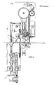
- Fig. 4 shows clearly that the pusher element carries row 98 through wrapping station B into folding station C. As a result of wrapping, sheet 99 is arranged in a "U" shape around row 98.
- the row 100 initially present in folding station C is handled at this location from the longitudinal fold unit 75 and the end folding unit 101.
- Fig. 5 shows the final position of row 98 in the longitudinal fold unit 75. It can clearly be seen that the tilted locking plate 77 prevents a displacement of row 98 against the packaging direction.
- An adhesive rod 103 provided with adhesive fingers 102 is then activated (see fig. 15) whereby the fold edge 80 is provided over its length with discrete adhesive points.
- the adhesive fingers 102 can move between a position indicated by dashed lines submerged in an adhesive container 105 and a position shown in full lines, in which adhesive fingers 102 touch fold edge 80.
- the lower folder 79 is provided with a number of slits 106 as a result of which lower folder 79 does not come into conflict with adhesive fingers 102 (fig. 14). Lower folder 79 can if required-be constructed from a number of separate lower folder members.
- Locking plate 77 is provided with gripping means 82 which grip sheet 99 on the fold edge 81 in the folding station.
- Gripping means 82 comprise an underpressure chamber 83 which is connected via a line 84 to a vacuum source (not shown).
- a wall 162 facing towards sheet 99 is provided with an elongate vacuum nozzle 163 which extends substantially over the whole length of the locking plate. It is likewise possible to use a large number of vacuum nozzles positioned at an interval from one another. Whatever the case, by applying a vacuum the fold edge 81 is sucked against wall 162 and held clear of row 98.
- Underpressure chamber 83 is coupled with the vacuum source as soon as row 98 reaches the position drawn in fig. 8, and the vacuum is disconnected when row 98 leaves the folding station.
- the adhesive be set more rapidly and to this end the upper folder 78 can be provided with heating means (not shown), whereby the setting time of the adhesive can be reduced from 6-10 secs. to 2-3 secs., with the upper folder at a temperature of ca. 100° C ' .
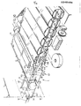
- Fig. 10-12 show in more detail the end folding unit 101 of folding station C which is intended for formation of the bottom fold of the sack bottom 165.
- the end folding unit comprises two end folders 110 which can move relative to the end wall positions 111 of a wrapped row 112 of elements which arrive from wrapping station B at folding station C.
- sheet 113 is in a "U" shape, so that when end folder 110 is moved from the position shown with dashed lines to the position shown with full lines a bottom fold part 115 is folded out of the excess portion 114.
- the end folder 110 is displaced as according to arrow 116 (fig. 11) onto the end wall position 111, whereby the other bottom fold part 117 is formed. Fingers 127 and 128 pass through the longitudinal slot 129 in the end folder.
- a guide strip 130 also prevents tilting of the covers.
- Printing unit 125 prints a code depending on whether the row 2 is supplied via feed unit 10 or feed unit 11. In this way is indicated from which cover forming machine the covers originate.
- fig. 15 shows a number of setting planes in the device 1.
- the plane 145 which goes through the lower folder 109 determines the stroke of the pusher element 28 into the longitudinal fold unit 75. 1
- the planes 146a and 146b go through the axial axis of a row of elements. Depending on the distance of these planes to the wrapping base plate 68 and the folding base plate 76 the radius r of each finger 102 is set so that the adhesive points are formed on the place where adjoining rows of folded sausage-like packagings are in line contact with one another. Moreover, soiling of the lower folder is prevented.
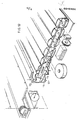
- the adhesive tape 147 used in fig. 16 is provided with two longitudinal edges 148 and 149 which are free of adhesive 150. An end wall position 151 can in this way be opened simply because these longitudinal edges 148 and 149 then serve as edges for gripping.
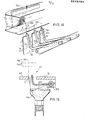
- Fig. 16 and 17 show the place and function of the adhesive support 166.
- the adhesive support 166 Prior to pusher element 28 being removed from wrapping station B and with it its fingers 127 and 128 from the end wall portions of the row 167, the adhesive support 166 is placed close to row 167, in order to replace finger 128, in a position P at a distance p.
- the function of finger 127 is taken over on one side by guide strip 130 and on the other side by the bottom fold part 115.
- the adhesive support is provided with a sensor 170 which is guided in a bushing 168 and under spring bias of a spring 169, with which on the one hand the distance p can be adjusted and on the other a minimum distance q.
- the adhesive support 166 is positioned at a distance Q before row 167, wrapping as shown in fig. 8 and 9 and adhering of the fold parts is performed.
- the outside surface 171 therefore serves hereby as supporting surface against which the fold parts to be adhered to each other are pressed using upper folder 78.
- a minimum requirement is that the adhesive support forms a support at the point of this contact face, but adhesive support 168 should preferably have a cross section which corresponds substantially to that of the row.
- a vacuum is generated in the space 173 situated between the row 167 and adhesive support 166.
- the adhesive support is provided for this purpose with passages 174 connected to a vacuum source, which passages run out into openings 176 arranged in a front wall 175.
- the packaging material moves to a position as shown with dashed lines 177.
- the adhesive support 166 is then moved towards the row 167 to a minimal distance Q, whereby the packaging material is creased such that an enduring packaging constriction 179 is formed.
- Adhesive support 166 is then removed and tilting of the covers out of row 167 is prevented by the now present packaging constriction 179 (see fig.
- the folding station comprises, apart from the first end folding unit 131 for forming the bottom fold 165 and the second end folding unit 132 for forming the discharge opening fold 182, a pusher element 186 located between both end folding units 131, 132, with which the packagings are aligned relative to the second end folding unit 132, namely so that the constriction 179 is guided by guide rods 187, 188 which are positioned transversely of the axial axis of each packaging.
- guide rods 187, 188 which are positioned transversely of the axial axis of each packaging.
- the fold-back means 190 comprise a pivoting arm 191 which is forced against discharge opening fold 182 under the influence of a spring 192.
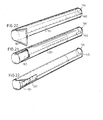
- the fold-back means further comprise a roller 194 mounted for rotation in a fork 193, so that the packaging 196 pressed against an end partition 195 acquires a form 197 of the discharge opening fold drawn in fig. 16. This situation is shown from another visual angle as according to arrow XVIII in fig. 18. Should no further process be carried out on packaging 196, it has the form as shown in fig. 20.
- the device according to the invention can also be provided with only one feed unit. All that is essential is that a sack shaped packaging is formed, out of which the rows of covers can easily be poured via the discharge opening.
Landscapes
- Engineering & Computer Science (AREA)
- Mechanical Engineering (AREA)
- Basic Packing Technique (AREA)
Applications Claiming Priority (2)
| Application Number | Priority Date | Filing Date | Title |
|---|---|---|---|
| NL8601428A NL8601428A (nl) | 1986-06-03 | 1986-06-03 | Inrichting voor het verpakken van een rij deksels, en de vervaardigde verpakking. |
| NL8601428 | 1986-06-03 |
Publications (2)
| Publication Number | Publication Date |
|---|---|
| EP0248464A1 true EP0248464A1 (de) | 1987-12-09 |
| EP0248464B1 EP0248464B1 (de) | 1991-03-27 |
Family
ID=19848112
Family Applications (1)
| Application Number | Title | Priority Date | Filing Date |
|---|---|---|---|
| EP87200897A Expired EP0248464B1 (de) | 1986-06-03 | 1987-05-14 | Vorrichtung zum Verpacken einer Reihe von Deckeln |
Country Status (6)
| Country | Link |
|---|---|
| US (1) | US4776149A (de) |
| EP (1) | EP0248464B1 (de) |
| JP (1) | JPS63152513A (de) |
| AU (1) | AU598546B2 (de) |
| DE (1) | DE3768859D1 (de) |
| NL (1) | NL8601428A (de) |
Cited By (2)
| Publication number | Priority date | Publication date | Assignee | Title |
|---|---|---|---|---|
| WO1999025624A1 (en) * | 1997-11-17 | 1999-05-27 | B.Ma. Snc Di Cafano Giuseppe E Raffaele | Easy-to-open packaging for lumps of sugar |
| WO2006057607A1 (en) * | 2004-11-25 | 2006-06-01 | Nordisk Plåtindustri Benetec Ab | Device and method for packaging a row of objects in a shrinkable foil |
Families Citing this family (4)
| Publication number | Priority date | Publication date | Assignee | Title |
|---|---|---|---|---|
| US4967537A (en) * | 1989-10-26 | 1990-11-06 | Adolph Coors Company | Apparatus for packaging articles |
| US5005340A (en) * | 1989-12-21 | 1991-04-09 | Fleetwood Systems, Inc. | Apparatus for inspecting and packaging can ends |
| US5471822A (en) * | 1991-09-30 | 1995-12-05 | Coors Brewing Company | Apparatus and method for packaging articles |
| JP2936458B2 (ja) * | 1995-10-31 | 1999-08-23 | 株式会社フジキカイ | 粒状物品の集合包装方法および装置 |
Citations (3)
| Publication number | Priority date | Publication date | Assignee | Title |
|---|---|---|---|---|
| US1757079A (en) * | 1928-02-07 | 1930-05-06 | Cynthia Mills | Band feeder |
| NL6513930A (de) * | 1964-11-07 | 1966-05-09 | ||
| GB1069649A (en) * | 1963-11-28 | 1967-05-24 | Auto Wrappers Norwich Ltd | An improved method of wrapping articles |
Family Cites Families (8)
| Publication number | Priority date | Publication date | Assignee | Title |
|---|---|---|---|---|
| US1069649A (en) * | 1911-11-22 | 1913-08-05 | Emanuel Rothschild | Box. |
| GB1211535A (en) * | 1966-11-24 | 1970-11-11 | Narottam Mohanlal Chauhan | Device for handling discrete laminar articles |
| US3866389A (en) * | 1973-05-09 | 1975-02-18 | Elsner Eng Works Inc | Roll wrapping machine |
| US4020617A (en) * | 1975-10-22 | 1977-05-03 | Hans Sickinger Co. | Heat shrink packaging machine |
| CH632203A5 (de) * | 1978-08-22 | 1982-09-30 | Sig Schweiz Industrieges | Einrichtung zur konstanthaltung des gewichtes von stapelpackungen. |
| CA1180992A (en) * | 1980-09-15 | 1985-01-15 | John E. Nordstrom | High speed wrapping machine |
| US4651500A (en) * | 1985-02-14 | 1987-03-24 | Valley Tissue Packaging, Inc. | Method and apparatus for wrapping rolls of paper |
| NL8501520A (nl) * | 1985-05-28 | 1986-12-16 | Thomassen & Drijver | Inrichting en werkwijze voor het verpakken van een rij schijfvormige elementen, en de vervaardigde verpakking. |
-
1986
- 1986-06-03 NL NL8601428A patent/NL8601428A/nl not_active Application Discontinuation
-
1987
- 1987-05-04 US US07/046,028 patent/US4776149A/en not_active Expired - Fee Related
- 1987-05-14 DE DE8787200897T patent/DE3768859D1/de not_active Expired - Fee Related
- 1987-05-14 EP EP87200897A patent/EP0248464B1/de not_active Expired
- 1987-05-30 JP JP62137575A patent/JPS63152513A/ja active Pending
- 1987-06-01 AU AU73761/87A patent/AU598546B2/en not_active Ceased
Patent Citations (3)
| Publication number | Priority date | Publication date | Assignee | Title |
|---|---|---|---|---|
| US1757079A (en) * | 1928-02-07 | 1930-05-06 | Cynthia Mills | Band feeder |
| GB1069649A (en) * | 1963-11-28 | 1967-05-24 | Auto Wrappers Norwich Ltd | An improved method of wrapping articles |
| NL6513930A (de) * | 1964-11-07 | 1966-05-09 |
Cited By (2)
| Publication number | Priority date | Publication date | Assignee | Title |
|---|---|---|---|---|
| WO1999025624A1 (en) * | 1997-11-17 | 1999-05-27 | B.Ma. Snc Di Cafano Giuseppe E Raffaele | Easy-to-open packaging for lumps of sugar |
| WO2006057607A1 (en) * | 2004-11-25 | 2006-06-01 | Nordisk Plåtindustri Benetec Ab | Device and method for packaging a row of objects in a shrinkable foil |
Also Published As
| Publication number | Publication date |
|---|---|
| AU598546B2 (en) | 1990-06-28 |
| DE3768859D1 (de) | 1991-05-02 |
| US4776149A (en) | 1988-10-11 |
| NL8601428A (nl) | 1988-01-04 |
| JPS63152513A (ja) | 1988-06-25 |
| AU7376187A (en) | 1987-12-10 |
| EP0248464B1 (de) | 1991-03-27 |
Similar Documents
| Publication | Publication Date | Title |
|---|---|---|
| US5340263A (en) | Apparatus for feeding packaging machines with stacks of sheet material | |
| US5251425A (en) | Enveloping device | |
| DE3443362C2 (de) | ||
| US3690650A (en) | Method and apparatus for feeding sheet material into a hopper | |
| US5203953A (en) | Process and apparatus for conveying labels to be transferred to a (cigarette) pack | |
| US4914893A (en) | Large size container banding apparatus | |
| US5218813A (en) | Bundling device and method | |
| US4179113A (en) | Apparatus for feeding leaflets to rapidly moving articles | |
| GB2027666A (en) | Method and apparatus for bundling sheets of thin material for example banknotes with tape | |
| EP0248464A1 (de) | Vorrichtung zum Verpacken einer Reihe von Deckeln | |
| US5535573A (en) | Apparatus (blank unit) for feeding blanks to an article which is to be wrapped | |
| US5197260A (en) | Method for packing articles, and machine for performing the method | |
| US4085564A (en) | Method and apparatus for making tray-type packets | |
| US3044772A (en) | Method of and means for handling and stacking folded sheets | |
| US4810153A (en) | Machine for receiving and stacking blanks of cardboard or like material of variable shape and format, successively cut out from a continuous web | |
| US4991374A (en) | Packaging machine for slide-fastener manufacture | |
| US4669248A (en) | Apparatus for packing a row of lids and the completed package | |
| US5304030A (en) | Device for the automatic feeding of stacks of cutouts to a user machine | |
| EP0680882B1 (de) | Maschine zum Verpacken von Kleidungsstücken, wie Strümpfe oder dergleichen, in Schachteln | |
| US4249844A (en) | Apparatus for accumulating stacks of note books or the like | |
| US5308056A (en) | Apparatus for stacking flat workpieces on a stacking table | |
| US7497067B2 (en) | Device for packing flat articles in transport containers | |
| CN100364861C (zh) | 包装以z字形状各回形环圈方式放置的柔软薄片物料的系统 | |
| US2991603A (en) | Stack handling machine for newspapers and the like | |
| US3579944A (en) | Apparatus and method for banding groups of envelopes |
Legal Events
| Date | Code | Title | Description |
|---|---|---|---|
| PUAI | Public reference made under article 153(3) epc to a published international application that has entered the european phase |
Free format text: ORIGINAL CODE: 0009012 |
|
| 17P | Request for examination filed |
Effective date: 19870514 |
|
| AK | Designated contracting states |
Kind code of ref document: A1 Designated state(s): BE DE FR GB IT NL |
|
| 17Q | First examination report despatched |
Effective date: 19890608 |
|
| ITF | It: translation for a ep patent filed | ||
| GRAA | (expected) grant |
Free format text: ORIGINAL CODE: 0009210 |
|
| AK | Designated contracting states |
Kind code of ref document: B1 Designated state(s): BE DE FR GB IT NL |
|
| REF | Corresponds to: |
Ref document number: 3768859 Country of ref document: DE Date of ref document: 19910502 |
|
| ET | Fr: translation filed | ||
| PLBE | No opposition filed within time limit |
Free format text: ORIGINAL CODE: 0009261 |
|
| STAA | Information on the status of an ep patent application or granted ep patent |
Free format text: STATUS: NO OPPOSITION FILED WITHIN TIME LIMIT |
|
| 26N | No opposition filed | ||
| PGFP | Annual fee paid to national office [announced via postgrant information from national office to epo] |
Ref country code: BE Payment date: 19950612 Year of fee payment: 9 |
|
| PG25 | Lapsed in a contracting state [announced via postgrant information from national office to epo] |
Ref country code: BE Effective date: 19960531 |
|
| BERE | Be: lapsed |
Owner name: THOMASSEN & DRIJVER-VERBLIFA N.V. Effective date: 19960531 |
|
| PGFP | Annual fee paid to national office [announced via postgrant information from national office to epo] |
Ref country code: FR Payment date: 19970527 Year of fee payment: 11 |
|
| PGFP | Annual fee paid to national office [announced via postgrant information from national office to epo] |
Ref country code: DE Payment date: 19970530 Year of fee payment: 11 |
|
| PGFP | Annual fee paid to national office [announced via postgrant information from national office to epo] |
Ref country code: NL Payment date: 19970531 Year of fee payment: 11 |
|
| PGFP | Annual fee paid to national office [announced via postgrant information from national office to epo] |
Ref country code: GB Payment date: 19970606 Year of fee payment: 11 |
|
| PG25 | Lapsed in a contracting state [announced via postgrant information from national office to epo] |
Ref country code: GB Free format text: LAPSE BECAUSE OF NON-PAYMENT OF DUE FEES Effective date: 19980514 |
|
| PG25 | Lapsed in a contracting state [announced via postgrant information from national office to epo] |
Ref country code: FR Free format text: LAPSE BECAUSE OF NON-PAYMENT OF DUE FEES Effective date: 19980531 |
|
| PG25 | Lapsed in a contracting state [announced via postgrant information from national office to epo] |
Ref country code: NL Free format text: LAPSE BECAUSE OF NON-PAYMENT OF DUE FEES Effective date: 19981201 |
|
| GBPC | Gb: european patent ceased through non-payment of renewal fee |
Effective date: 19980514 |
|
| NLV4 | Nl: lapsed or anulled due to non-payment of the annual fee |
Effective date: 19981201 |
|
| PG25 | Lapsed in a contracting state [announced via postgrant information from national office to epo] |
Ref country code: DE Free format text: LAPSE BECAUSE OF NON-PAYMENT OF DUE FEES Effective date: 19990302 |
|
| REG | Reference to a national code |
Ref country code: FR Ref legal event code: ST |
|
| PG25 | Lapsed in a contracting state [announced via postgrant information from national office to epo] |
Ref country code: IT Free format text: LAPSE BECAUSE OF NON-PAYMENT OF DUE FEES;WARNING: LAPSES OF ITALIAN PATENTS WITH EFFECTIVE DATE BEFORE 2007 MAY HAVE OCCURRED AT ANY TIME BEFORE 2007. THE CORRECT EFFECTIVE DATE MAY BE DIFFERENT FROM THE ONE RECORDED. Effective date: 20050514 |