EP0248317A2 - Ossature spatiale réticulaire - Google Patents
Ossature spatiale réticulaire Download PDFInfo
- Publication number
- EP0248317A2 EP0248317A2 EP87107596A EP87107596A EP0248317A2 EP 0248317 A2 EP0248317 A2 EP 0248317A2 EP 87107596 A EP87107596 A EP 87107596A EP 87107596 A EP87107596 A EP 87107596A EP 0248317 A2 EP0248317 A2 EP 0248317A2
- Authority
- EP
- European Patent Office
- Prior art keywords
- rod
- elements
- length
- reticular
- spatial structure
- Prior art date
- Legal status (The legal status is an assumption and is not a legal conclusion. Google has not performed a legal analysis and makes no representation as to the accuracy of the status listed.)
- Granted
Links
Images


Classifications
-
- E—FIXED CONSTRUCTIONS
- E04—BUILDING
- E04B—GENERAL BUILDING CONSTRUCTIONS; WALLS, e.g. PARTITIONS; ROOFS; FLOORS; CEILINGS; INSULATION OR OTHER PROTECTION OF BUILDINGS
- E04B1/00—Constructions in general; Structures which are not restricted either to walls, e.g. partitions, or floors or ceilings or roofs
- E04B1/18—Structures comprising elongated load-supporting parts, e.g. columns, girders, skeletons
- E04B1/19—Three-dimensional [3D] framework structures
- E04B1/1903—Connecting nodes specially adapted therefor
- E04B1/1906—Connecting nodes specially adapted therefor with central spherical, semispherical or polyhedral connecting element
-
- E—FIXED CONSTRUCTIONS
- E04—BUILDING
- E04B—GENERAL BUILDING CONSTRUCTIONS; WALLS, e.g. PARTITIONS; ROOFS; FLOORS; CEILINGS; INSULATION OR OTHER PROTECTION OF BUILDINGS
- E04B1/00—Constructions in general; Structures which are not restricted either to walls, e.g. partitions, or floors or ceilings or roofs
- E04B1/32—Arched structures; Vaulted structures; Folded structures
- E04B1/3211—Structures with a vertical rotation axis or the like, e.g. semi-spherical structures
-
- E—FIXED CONSTRUCTIONS
- E04—BUILDING
- E04B—GENERAL BUILDING CONSTRUCTIONS; WALLS, e.g. PARTITIONS; ROOFS; FLOORS; CEILINGS; INSULATION OR OTHER PROTECTION OF BUILDINGS
- E04B7/00—Roofs; Roof construction with regard to insulation
- E04B7/08—Vaulted roofs
- E04B7/10—Shell structures, e.g. of hyperbolic-parabolic shape; Grid-like formations acting as shell structures; Folded structures
- E04B7/105—Grid-like structures
-
- E—FIXED CONSTRUCTIONS
- E04—BUILDING
- E04B—GENERAL BUILDING CONSTRUCTIONS; WALLS, e.g. PARTITIONS; ROOFS; FLOORS; CEILINGS; INSULATION OR OTHER PROTECTION OF BUILDINGS
- E04B1/00—Constructions in general; Structures which are not restricted either to walls, e.g. partitions, or floors or ceilings or roofs
- E04B1/18—Structures comprising elongated load-supporting parts, e.g. columns, girders, skeletons
- E04B1/19—Three-dimensional [3D] framework structures
- E04B1/1903—Connecting nodes specially adapted therefor
- E04B1/1909—Connecting nodes specially adapted therefor with central cylindrical connecting element
-
- E—FIXED CONSTRUCTIONS
- E04—BUILDING
- E04B—GENERAL BUILDING CONSTRUCTIONS; WALLS, e.g. PARTITIONS; ROOFS; FLOORS; CEILINGS; INSULATION OR OTHER PROTECTION OF BUILDINGS
- E04B1/00—Constructions in general; Structures which are not restricted either to walls, e.g. partitions, or floors or ceilings or roofs
- E04B1/18—Structures comprising elongated load-supporting parts, e.g. columns, girders, skeletons
- E04B1/19—Three-dimensional [3D] framework structures
- E04B2001/1924—Struts specially adapted therefor
- E04B2001/1927—Struts specially adapted therefor of essentially circular cross section
-
- E—FIXED CONSTRUCTIONS
- E04—BUILDING
- E04B—GENERAL BUILDING CONSTRUCTIONS; WALLS, e.g. PARTITIONS; ROOFS; FLOORS; CEILINGS; INSULATION OR OTHER PROTECTION OF BUILDINGS
- E04B1/00—Constructions in general; Structures which are not restricted either to walls, e.g. partitions, or floors or ceilings or roofs
- E04B1/18—Structures comprising elongated load-supporting parts, e.g. columns, girders, skeletons
- E04B1/19—Three-dimensional [3D] framework structures
- E04B2001/1924—Struts specially adapted therefor
- E04B2001/1942—Struts adjustable in length
-
- E—FIXED CONSTRUCTIONS
- E04—BUILDING
- E04B—GENERAL BUILDING CONSTRUCTIONS; WALLS, e.g. PARTITIONS; ROOFS; FLOORS; CEILINGS; INSULATION OR OTHER PROTECTION OF BUILDINGS
- E04B1/00—Constructions in general; Structures which are not restricted either to walls, e.g. partitions, or floors or ceilings or roofs
- E04B1/18—Structures comprising elongated load-supporting parts, e.g. columns, girders, skeletons
- E04B1/19—Three-dimensional [3D] framework structures
- E04B2001/1957—Details of connections between nodes and struts
- E04B2001/196—Screw connections with axis parallel to the main axis of the strut
-
- E—FIXED CONSTRUCTIONS
- E04—BUILDING
- E04B—GENERAL BUILDING CONSTRUCTIONS; WALLS, e.g. PARTITIONS; ROOFS; FLOORS; CEILINGS; INSULATION OR OTHER PROTECTION OF BUILDINGS
- E04B1/00—Constructions in general; Structures which are not restricted either to walls, e.g. partitions, or floors or ceilings or roofs
- E04B1/18—Structures comprising elongated load-supporting parts, e.g. columns, girders, skeletons
- E04B1/19—Three-dimensional [3D] framework structures
- E04B2001/1957—Details of connections between nodes and struts
- E04B2001/1963—Screw connections with axis at an angle, e.g. perpendicular, to the main axis of the strut
-
- E—FIXED CONSTRUCTIONS
- E04—BUILDING
- E04B—GENERAL BUILDING CONSTRUCTIONS; WALLS, e.g. PARTITIONS; ROOFS; FLOORS; CEILINGS; INSULATION OR OTHER PROTECTION OF BUILDINGS
- E04B1/00—Constructions in general; Structures which are not restricted either to walls, e.g. partitions, or floors or ceilings or roofs
- E04B1/18—Structures comprising elongated load-supporting parts, e.g. columns, girders, skeletons
- E04B1/19—Three-dimensional [3D] framework structures
- E04B2001/1981—Three-dimensional [3D] framework structures characterised by the grid type of the outer planes of the framework
- E04B2001/1987—Three-dimensional [3D] framework structures characterised by the grid type of the outer planes of the framework triangular grid
-
- E—FIXED CONSTRUCTIONS
- E04—BUILDING
- E04B—GENERAL BUILDING CONSTRUCTIONS; WALLS, e.g. PARTITIONS; ROOFS; FLOORS; CEILINGS; INSULATION OR OTHER PROTECTION OF BUILDINGS
- E04B1/00—Constructions in general; Structures which are not restricted either to walls, e.g. partitions, or floors or ceilings or roofs
- E04B1/32—Arched structures; Vaulted structures; Folded structures
- E04B2001/3217—Auxiliary supporting devices used during erection of the arched structures
-
- E—FIXED CONSTRUCTIONS
- E04—BUILDING
- E04B—GENERAL BUILDING CONSTRUCTIONS; WALLS, e.g. PARTITIONS; ROOFS; FLOORS; CEILINGS; INSULATION OR OTHER PROTECTION OF BUILDINGS
- E04B1/00—Constructions in general; Structures which are not restricted either to walls, e.g. partitions, or floors or ceilings or roofs
- E04B1/32—Arched structures; Vaulted structures; Folded structures
- E04B2001/3235—Arched structures; Vaulted structures; Folded structures having a grid frame
- E04B2001/3241—Frame connection details
- E04B2001/3247—Nodes
-
- E—FIXED CONSTRUCTIONS
- E04—BUILDING
- E04B—GENERAL BUILDING CONSTRUCTIONS; WALLS, e.g. PARTITIONS; ROOFS; FLOORS; CEILINGS; INSULATION OR OTHER PROTECTION OF BUILDINGS
- E04B1/00—Constructions in general; Structures which are not restricted either to walls, e.g. partitions, or floors or ceilings or roofs
- E04B1/32—Arched structures; Vaulted structures; Folded structures
- E04B2001/3235—Arched structures; Vaulted structures; Folded structures having a grid frame
- E04B2001/3252—Covering details
-
- E—FIXED CONSTRUCTIONS
- E04—BUILDING
- E04B—GENERAL BUILDING CONSTRUCTIONS; WALLS, e.g. PARTITIONS; ROOFS; FLOORS; CEILINGS; INSULATION OR OTHER PROTECTION OF BUILDINGS
- E04B1/00—Constructions in general; Structures which are not restricted either to walls, e.g. partitions, or floors or ceilings or roofs
- E04B1/32—Arched structures; Vaulted structures; Folded structures
- E04B2001/3294—Arched structures; Vaulted structures; Folded structures with a faceted surface
Definitions
- the present invention represents a particular apparatus related to a spatial structure which can be obtained, preferably but not necessarily, by means of a pneumatic lifting system and is composed of extendable modular elements, coupled to the nodes by means of spherical hollow hinges, all the elements being assembled on a substantially plane level on a membrane fixed to a perimetral foundation ridge or the like.
- a method for performing a covering, preferably dome- shaped and pneumatically erected, which is substantially constituted by a plurality of rod-like elements which are assembled and connected at their end to non-spherical nodes and rigidly fixed to a membrane anchored peripherally on a planar surface which in practice delimits the covering region.
- variable-length rod-like elements are furthermore provided which are still assembled on a base plane, coupling their ends to connecting nodes, the rod-like elements having a limited possibility of articulation with respect to the nodes, during the phase of automatic raising.
- an erection of the supporting structure of the covering is provided by means of a pneumatic action or the like, acting on said membrane so that, in reaching the desired configuration, the variable-length rod-like elements extend telescopically until they reach a selected length, by rotating about their own axis, but not about the geometrical center of the node.
- locking means intervene which are directly provided in the rod-like elements, and prevent said elements from assuming a length which differs from the preset one.
- the various rod-like elements assembled beforehand on a base plane, allow to achieve a precise automatic positioning thereof to provide a specific spatial structure substantially in the shape of a dome or of a vault and pneumatically erected.
- the-connection between the known rod-like elements of the non-spherical type is generally provided by means of complex elements with different shapes which lock into or insert in corresponding specifically provided seats.
- the covering membrane which is rigidly coupled to the assembly of the node, can transmit directly to the metallic structure stresses and vibrations which are capable of triggering moments which can be harmful to the local stability of the rod-node assembly, due to the lack of concentricity of the axes of the rods with respect to the geometrical center of the node as the angle of incidence of the axes of the rod-like elements varies with respect to the vertical axis which passes through the center of the nodes.
- the aim of the invention is indeed to eliminate the above described disadvantages by providing a reticular structure for variable geometries, including the global ones which can be contained in spherical shapes and preferably with pneumatic forming, which offers the advantage of greatly facilitating all the steps of making the components, their assembly, raising the structure, disassembly of the components and their possible recovery for other purposes or future uses of the same structure.
- a particular object of the present invention is to provide a reticular structure, provided with a more efficient and simplified perimetral anchoring/connection node for the various rod-like elements connected thereto and which, even when the structure is erected, can be replaced or makes it possible to replace or eliminate one or more rod-like elements connected thereto, with the possibility of facilitating their locking once the designed preset position has been reached.
- a reticular spatial structure preferably pneumatically erected, composed of modular elements, according to the invention, comprising a plurality of perimetral rod-like elements associable, at their ends, with perimetral nodes, a plurality of variable-length rod-like elements pivotable, at their ends, to connecting nodes provided, like the perimetral nodes, with a spherical contact surface adapted to allow the rotation of at least part of said variable-length rod-like elements both about the axis of said elements and with respect to the geometrical center of the various nodes, for the extension of said variable-length elements during the pneumatic raising of the framework preassembled on a substantially horizontal base plane for the formation of a reticular spatial structure, preferably but not necessarily in the shape of a dome, locking means being furthermore provided to prevent the return of said variable-length rod-like elements to lengths which differ from the intended final extension lengths, characterized in that said connecting no
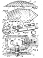
- the pneumatically erected reticular spatial structure comprises a plurality of perimetral rod-like elements, indicated by 1, which advantageously but not necessarily are of the fixed-length type, and at their ends are coupled to perimetral nodes, generally indicated by the reference numeral 2, after arranging the lower plates 12a on the resting plane according to the preset geometry.
- the structure is arranged on a base plane on a membrane 13, anchored peripherally to the pneumatically sealed foundations, arranging the rod-like elements 1 according to a geometrical pattern provided by the project and connecting them to the perimetral nodes.
- the reticular structure furthermore comprises variable-length rod-like elements, generally indicated by the reference numeral 10 which also, at their ends, are articulated to connecting nodes 11 with the possibility of rotating about their own axis of rotation with respect to the geometrical center of said connecting nodes; furthermore, part of the rod-like elements 10 are articulated also to the perimetral nodes 2, so as to create, in practice, a plane grid applied both to the membrane 13, at selected points, and to the perimetral foundation plinths.
- variable-length rod-like elements generally indicated by the reference numeral 10 which also, at their ends, are articulated to connecting nodes 11 with the possibility of rotating about their own axis of rotation with respect to the geometrical center of said connecting nodes; furthermore, part of the rod-like elements 10 are articulated also to the perimetral nodes 2, so as to create, in practice, a plane grid applied both to the membrane 13, at selected points, and to the perimetral foundation plinths.
- the entire apparatus of the connecting node 11 is provided with a lower plate 12a and with an upper plate 12b securing the membrane 13 between themselves by means of a threaded connecting pivot 14 suspended, rocker-like, from the node.
- the plates 12a and 12b are provided, on their face connecting the membrane 13, with annular recesses, indicated by 15, which facilitate the adhesion of the membrane to the plates, in order to ensure a waterproof connection.
- the pivot 14 is suspended from the hollow body, indicated by 20, which is substantially composed of a lower base 21 and of an upper base 22 connected to a wall having the inner and outer surfaces shaped according to concentric spherical surfaces.
- the lower base 21 defines, in the region of coupling to the pivot 14, a coupling seat 25 shaped like a spherical portion, in which a complementarily shaped nut 26 engages and allows a variable positioning of the hollow body 20 with respect to the pivot 14.
- a ring 26 of elastically deformable material is interposed between the lower base 21 and the upper plate 12 and acts as a shock absorber, absorbing part of the vibrations transmitted by the membrane to the metallic structure.
- a plurality of openings 30 is provided on the wall 23 for the passage of the locking bolts 34 required to lock the ends of the rod-like elements 10.
- the rod-like elements 10 are provided with a terminal body 31 which defines a spherical seat 32 in the region of coupling to the wall 23 which has a curvature matching the curvature of the node spherical surface, so as to achieve a stable coupling also when the angle of the terminal body with respect to the node varies.
- a shaped body 33 which has a spherical configuration in the region of contact to the inner surface, so as to ensure a perfect coupling also of the surfaces in contact inside the node, as the angle of incidence of the terminal body with respect to the node varies.
- the upper base 22 is screwed to the hollow body 20 so as to be removable and to permit access to the bolts 34 for the final locking in the preset position of the various rod-like elements once their extension is completed to reach the preset length after the structure has been erected.
- the structure can be raised, as previously mentioned, by pneumatic means, but conceptually nothing varies if it is raised by means different from pneumatic ones, such as, for example, by means of cables, jacks or other mechanical systems.
- the various variable-length rod-like elements 10 have a tubular body, indicated by 40; which, at least at one end, defines a threaded portion 41 with which a ring nut 42 engages.
- the ring nut 42 is provided,with an abutment 43, which, in cooperation with the end of the tubular body 40, defines the snap coupling seat 44 for a locking means which is advantageously constituted by a split elastic ring 45 housed in a piston-like body 46 which is slideable within the tubular body 10.
- the elastic ring 45 is positioned on the body 46 on the opposite side with respect to the terminal body 31.
- a threaded portion 47 is provided in the region of coupling between the piston body 46 and the terminal body 31, and a locking nut 48 is engaged therein once the desired extension has been performed.
- the piston-like body 46 is housed in the tubular body 40 and supports the elastic ring 45.
- the ring locks in the coupling seat 44 defined by the abutment 43 and by the end of the tubular body 40 thus preventing any further axial motion of the tubular body with respect to the piston-like body.
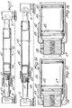
- Figs. 17, 18 and 19 it is illustrated a rod-like element with variable working length, according to another aspect of the invention.
- an outer tubular body 60 has, at one of its ends, an outer threaded portion 61 engaging a sleeve 62 which inwardly defines an abutment 63 delimitating, with the end of the outer tubular body 60, a seat 64 in which split elastic rings 65 are provided acting in compression.
- the threaded means 66 arranged outside the sleeve 62 to radially compress the rings 65.
- An inner tubular body 70 is accommodated inside the tubular body 60 and defines a piston-like portion 71 providing a locking seat 72 in which said elastic rings 65 are locked to prevent the reentry of the inner tubular body 70 once it has been extended to the preset length.
- a device for performing the final extension can be provided as illustrated in figs. 20 and 21.
- Such a device comprises a threaded sleeve 80 which is connected to the terminal body 81 and engages rotatably with a threaded portion 83 defined by the tubular element 82.
- the threaded sleeve 80 is provided with a diametral hole 84 which is engageable by a tool to rotate the sleeve so as to "pull" the tubular element 82 until the snap- together coupling of the elastic rings is achieved.
- an element for locking the reentry of the tubular element 82 which consists of a diametral body 85 diametrally supported by the tubular element 82.
- the body 85 has a minimum length such as to be included in the dimensions of the tubular element 82:and is extendable to engage in abutment with the sleeve provided on the outer tubular element.
- the body 85 is composed of a first part 85a and of a second part 85b with a mutual coupling of the bolt-threaded seat type.
- the perimetral nodes 2 can be made similar to the nodes 11, assembling them in such a way as to make them capable of oscillating in order to assume the correct position, or possibly a hollow body 20 can be fixed with a preset inclination to an upper base plate 50 which, by means of the locking tension elements 51, locks onto a lower base plate 52 which can be connected to a plinth for anchoring to the ground or to the perimetral foundation ridge.
- a plane reticular structure is applied to a membrane 13 which is peripherally anchored and pneumatically sealed, by connecting to one another the perimetral nodes of the foundations of the rod-like elements 1, as well as variable-length rod-like elements 10 to the connecting nodes, according to a preset pattern, then air is forced below the membrane, performing the gradual raising, which, as already mentioned above, can also be achieved with different means.
- the rod-like elements 10 extend and rotate both about their own axis and about the various geometrical centers of the connecting nodes until, once the preset working length has been reached the rod-like elements lock at the set position.
- the ring nuts of the locking nuts and of the various rod-like elements are tightened, and then the rod-like elements are locked with respect to the nodes by using the bolt 14 which can be reached from the interior of the hollow body 20, thus achieving also the locking at all the nodes.
- the invention achieves the proposed aims, and in particular the fact is stressed that the reticular structure, according to the invention, has a remarkably easy assembly, due to the presence of components similar to one another, composed of nodes and variable-length rod-like elements, which have the possibility of reaching a preset length during the pneumatic raising.
- the system makes it possible to release quickly the various lockings in order to recover the elements at a substantially plane level, preferably through a pneumatic disassembly.
- variable-length rod-like elements can be provided, according to the requirements, either with both ends extendable or with one fixed end and with one extendable end.
- the materials employed may be any according to the requirements
Landscapes
- Engineering & Computer Science (AREA)
- Architecture (AREA)
- Physics & Mathematics (AREA)
- Electromagnetism (AREA)
- Civil Engineering (AREA)
- Structural Engineering (AREA)
- Separation Using Semi-Permeable Membranes (AREA)
- Tents Or Canopies (AREA)
- Pivots And Pivotal Connections (AREA)
- Organic Low-Molecular-Weight Compounds And Preparation Thereof (AREA)
- Hinges (AREA)
- Apparatus Associated With Microorganisms And Enzymes (AREA)
- Threshing Machine Elements (AREA)
- Biological Depolymerization Polymers (AREA)
- Vehicle Body Suspensions (AREA)
- Surgical Instruments (AREA)
Priority Applications (1)
| Application Number | Priority Date | Filing Date | Title |
|---|---|---|---|
| AT87107596T ATE72469T1 (de) | 1986-06-05 | 1987-05-25 | Retikulare raeumliche struktur. |
Applications Claiming Priority (2)
| Application Number | Priority Date | Filing Date | Title |
|---|---|---|---|
| IT2068786 | 1986-06-05 | ||
| IT20687/86A IT1190044B (it) | 1986-06-05 | 1986-06-05 | Tstruttura reticolare spaziale composta da elementi modulari estensibili telescopicamente e vincolati a nodi a cerniera sferica |
Publications (3)
| Publication Number | Publication Date |
|---|---|
| EP0248317A2 true EP0248317A2 (fr) | 1987-12-09 |
| EP0248317A3 EP0248317A3 (en) | 1990-05-30 |
| EP0248317B1 EP0248317B1 (fr) | 1992-02-05 |
Family
ID=11170577
Family Applications (1)
| Application Number | Title | Priority Date | Filing Date |
|---|---|---|---|
| EP87107596A Expired - Lifetime EP0248317B1 (fr) | 1986-06-05 | 1987-05-25 | Ossature spatiale réticulaire |
Country Status (13)
| Country | Link |
|---|---|
| US (1) | US4796389A (fr) |
| EP (1) | EP0248317B1 (fr) |
| JP (1) | JPS6335978A (fr) |
| AT (1) | ATE72469T1 (fr) |
| AU (1) | AU597377B2 (fr) |
| CA (1) | CA1287961C (fr) |
| DE (1) | DE3776593D1 (fr) |
| ES (1) | ES2030677T3 (fr) |
| IL (1) | IL82707A0 (fr) |
| IT (1) | IT1190044B (fr) |
| NZ (1) | NZ220552A (fr) |
| SU (1) | SU1570655A3 (fr) |
| ZA (1) | ZA874051B (fr) |
Cited By (2)
| Publication number | Priority date | Publication date | Assignee | Title |
|---|---|---|---|---|
| FR2628461A1 (fr) * | 1988-03-14 | 1989-09-15 | Overbeeke Daniel | Barre pour construction multidimensionnelle en treillis |
| GB2300240A (en) * | 1995-04-25 | 1996-10-30 | Bailey Ralph Peter Steven | Constructional system |
Families Citing this family (19)
| Publication number | Priority date | Publication date | Assignee | Title |
|---|---|---|---|---|
| JP2750278B2 (ja) * | 1995-04-19 | 1998-05-13 | 小川テント株式会社 | トラス構築用ジョイント及びトラス構築用ジョイントユニット |
| US6065263A (en) * | 1997-06-27 | 2000-05-23 | Kaieitechno Co., Ltd. | Connecting structure for concrete block and connector used therefor |
| US5996288A (en) * | 1997-10-20 | 1999-12-07 | Aiken; Ernest G | Geodesic domes and improved joints therefor |
| GB0003085D0 (en) * | 2000-02-10 | 2000-03-29 | Peter Dann Limited | Arch structure |
| US20090113816A1 (en) * | 2002-03-15 | 2009-05-07 | Jean-Christophe Jacques Kling | Architectural system using a retractable strut aligned in a base plane and an extension strut protruding acutely from the base plane |
| US6887009B1 (en) | 2002-10-01 | 2005-05-03 | Conservatek Industries, Inc. | Cylindrical joint and reticulated frame structure |
| US7921613B2 (en) * | 2008-06-11 | 2011-04-12 | Koichi Paul Nii | Terraced structured land joint and assembly system |
| DE202009000481U1 (de) * | 2009-01-13 | 2010-06-02 | B.T. Innovation Gmbh | Spannschloss für Betonfertigteile |
| JP5500913B2 (ja) * | 2009-08-27 | 2014-05-21 | 新日鉄住金エンジニアリング株式会社 | ラチスシェル構造の節点構造及びその施工方法 |
| JP5489600B2 (ja) * | 2009-08-27 | 2014-05-14 | 新日鉄住金エンジニアリング株式会社 | ラチスシェル構造の節点構造及びその施工方法 |
| JP2010229811A (ja) * | 2010-06-16 | 2010-10-14 | Glenn A Reynolds | 同軸接合システム |
| CN102995748B (zh) * | 2012-12-06 | 2015-01-14 | 北京工业大学 | 充气膜压杆及作法 |
| EP2921600B1 (fr) * | 2014-03-19 | 2016-05-18 | Airbus Operations GmbH | Joint rotatif, kit de construction de charpente et procédé de construction d'une ossature |
| US20170159280A1 (en) * | 2014-08-15 | 2017-06-08 | Kenneth E. Nunn | Construction and hub structures therefrom |
| EP3098463B1 (fr) * | 2015-05-26 | 2018-03-14 | Airbus Operations GmbH | Joint rotatif, kit de construction d'ossature et procédé de fabrication d'un joint rotatif |
| EP3135833B1 (fr) * | 2015-08-27 | 2019-05-08 | Airbus Operations GmbH | Joint rotatif, kit de construction de structure en treillies avec des joints rotatifs de structure et procédé de fabrication d'un joint rotatif |
| ES2659841A1 (es) * | 2018-01-11 | 2018-03-19 | Universidad Politécnica de Madrid | Estructura reticular transformable |
| TWI770599B (zh) * | 2020-09-04 | 2022-07-11 | 賴祥瑞 | 模組化連接裝置 |
| CN113389277B (zh) * | 2021-03-15 | 2023-07-11 | 中国水利水电第九工程局有限公司 | 一种双层钢结构网架复合膜结构建筑物屋顶施工方法 |
Family Cites Families (9)
| Publication number | Priority date | Publication date | Assignee | Title |
|---|---|---|---|---|
| US3006670A (en) * | 1959-06-02 | 1961-10-31 | Goodyear Aircraft Corp | Frame for supporting domed structures |
| US3129531A (en) * | 1961-11-14 | 1964-04-21 | Connor Robert | Reinforced building structure |
| US3973370A (en) * | 1972-05-22 | 1976-08-10 | Mcallister Jack G | Method of making a frame assembly |
| US3918233A (en) * | 1973-02-27 | 1975-11-11 | Harold Graves Simpson | Construction system |
| US4296585A (en) * | 1978-05-30 | 1981-10-27 | Dante Bini | Permanent weather covers |
| EP0070096A3 (fr) * | 1981-07-14 | 1983-05-11 | Norman Ashley Boyce | Ossature rigide pour bâtiment pourvue d'un élément gonflable |
| DE8123976U1 (de) * | 1981-08-17 | 1982-02-04 | Mero-Raumstruktur GmbH & Co Würzburg, 8700 Würzburg | Bausatz zur herstellung einer aus einzelnen plattenfoermigen dachelementen zusammenzusetzenden dachhaut |
| ZA834078B (fr) * | 1982-03-05 | 1984-01-23 | ||
| US4669909A (en) * | 1984-03-02 | 1987-06-02 | Galan Inchaurbe Jose M | Spacial structure |
-
1986
- 1986-06-05 IT IT20687/86A patent/IT1190044B/it active
-
1987
- 1987-05-25 DE DE8787107596T patent/DE3776593D1/de not_active Expired - Fee Related
- 1987-05-25 EP EP87107596A patent/EP0248317B1/fr not_active Expired - Lifetime
- 1987-05-25 AT AT87107596T patent/ATE72469T1/de not_active IP Right Cessation
- 1987-05-25 ES ES198787107596T patent/ES2030677T3/es not_active Expired - Lifetime
- 1987-05-29 IL IL82707A patent/IL82707A0/xx not_active IP Right Cessation
- 1987-06-01 US US07/055,955 patent/US4796389A/en not_active Expired - Fee Related
- 1987-06-03 CA CA000538680A patent/CA1287961C/fr not_active Expired - Lifetime
- 1987-06-04 AU AU73846/87A patent/AU597377B2/en not_active Ceased
- 1987-06-04 JP JP62139075A patent/JPS6335978A/ja active Pending
- 1987-06-04 NZ NZ220552A patent/NZ220552A/en unknown
- 1987-06-05 ZA ZA874051A patent/ZA874051B/xx unknown
- 1987-06-05 SU SU874202721A patent/SU1570655A3/ru active
Cited By (2)
| Publication number | Priority date | Publication date | Assignee | Title |
|---|---|---|---|---|
| FR2628461A1 (fr) * | 1988-03-14 | 1989-09-15 | Overbeeke Daniel | Barre pour construction multidimensionnelle en treillis |
| GB2300240A (en) * | 1995-04-25 | 1996-10-30 | Bailey Ralph Peter Steven | Constructional system |
Also Published As
| Publication number | Publication date |
|---|---|
| SU1570655A3 (ru) | 1990-06-07 |
| US4796389A (en) | 1989-01-10 |
| CA1287961C (fr) | 1991-08-27 |
| IT1190044B (it) | 1988-02-10 |
| ES2030677T3 (es) | 1992-11-16 |
| JPS6335978A (ja) | 1988-02-16 |
| EP0248317A3 (en) | 1990-05-30 |
| AU7384687A (en) | 1987-12-10 |
| EP0248317B1 (fr) | 1992-02-05 |
| IT8620687A1 (it) | 1987-12-05 |
| IT8620687A0 (it) | 1986-06-05 |
| IL82707A0 (en) | 1987-11-30 |
| ATE72469T1 (de) | 1992-02-15 |
| AU597377B2 (en) | 1990-05-31 |
| DE3776593D1 (de) | 1992-03-19 |
| ZA874051B (en) | 1988-02-24 |
| NZ220552A (en) | 1990-04-26 |
Similar Documents
| Publication | Publication Date | Title |
|---|---|---|
| EP0248317B1 (fr) | Ossature spatiale réticulaire | |
| US5943837A (en) | Quick erect shelter apparatus | |
| US4296585A (en) | Permanent weather covers | |
| CA1269585A (fr) | Moyeu et capuchon de perche pour armature de tente | |
| US2962034A (en) | Shelter and method of making same | |
| US6345638B1 (en) | Multiple peak cable tent | |
| AU603861B2 (en) | Node member for use in building a geodesic structure | |
| US5423341A (en) | Unitized foldable tent frame | |
| US3059658A (en) | Shelter framework | |
| US4324083A (en) | Space frame | |
| US3922827A (en) | Hyperbolic tower structure | |
| AU674258B2 (en) | Emergency shelter | |
| US5566516A (en) | Spherical grid | |
| WO1994024380A9 (fr) | Abri de securite | |
| CN110894759B (zh) | 一种输电线路架设电力电线杆 | |
| WO1996025572A2 (fr) | Systemes gonflables de support de toit | |
| GB2192965A (en) | Space frame system | |
| IT1260770B (it) | Giunto per strutture tridimensionali reticolari | |
| US2359683A (en) | Horizontal tank and support therefor | |
| US4190990A (en) | Frame assembly | |
| US9151035B2 (en) | Double axis frame strut | |
| CH642130A5 (en) | Process for forming a dome-shaped spatial roof and reticular structure for effecting said process | |
| CN215170198U (zh) | 井下扇形风障骨架 | |
| WO2000026544A1 (fr) | Ameliorations concernant des structures provisoires | |
| US3393480A (en) | Antenna supporting tower and method of constructing same |
Legal Events
| Date | Code | Title | Description |
|---|---|---|---|
| PUAI | Public reference made under article 153(3) epc to a published international application that has entered the european phase |
Free format text: ORIGINAL CODE: 0009012 |
|
| AK | Designated contracting states |
Kind code of ref document: A2 Designated state(s): AT CH DE ES FR GB IT LI |
|
| PUAL | Search report despatched |
Free format text: ORIGINAL CODE: 0009013 |
|
| AK | Designated contracting states |
Kind code of ref document: A3 Designated state(s): AT CH DE ES FR GB IT LI |
|
| RHK1 | Main classification (correction) |
Ipc: E04B 1/19 |
|
| 17P | Request for examination filed |
Effective date: 19900620 |
|
| 17Q | First examination report despatched |
Effective date: 19910326 |
|
| GRAA | (expected) grant |
Free format text: ORIGINAL CODE: 0009210 |
|
| AK | Designated contracting states |
Kind code of ref document: B1 Designated state(s): AT CH DE ES FR GB IT LI |
|
| PG25 | Lapsed in a contracting state [announced via postgrant information from national office to epo] |
Ref country code: AT Effective date: 19920205 |
|
| REF | Corresponds to: |
Ref document number: 72469 Country of ref document: AT Date of ref document: 19920215 Kind code of ref document: T |
|
| REF | Corresponds to: |
Ref document number: 3776593 Country of ref document: DE Date of ref document: 19920319 |
|
| ET | Fr: translation filed | ||
| ITF | It: translation for a ep patent filed | ||
| REG | Reference to a national code |
Ref country code: ES Ref legal event code: FG2A Ref document number: 2030677 Country of ref document: ES Kind code of ref document: T3 |
|
| PLBE | No opposition filed within time limit |
Free format text: ORIGINAL CODE: 0009261 |
|
| STAA | Information on the status of an ep patent application or granted ep patent |
Free format text: STATUS: NO OPPOSITION FILED WITHIN TIME LIMIT |
|
| 26N | No opposition filed | ||
| PGFP | Annual fee paid to national office [announced via postgrant information from national office to epo] |
Ref country code: GB Payment date: 19940503 Year of fee payment: 8 |
|
| PGFP | Annual fee paid to national office [announced via postgrant information from national office to epo] |
Ref country code: CH Payment date: 19940919 Year of fee payment: 8 |
|
| PGFP | Annual fee paid to national office [announced via postgrant information from national office to epo] |
Ref country code: ES Payment date: 19940927 Year of fee payment: 8 Ref country code: DE Payment date: 19940927 Year of fee payment: 8 |
|
| PGFP | Annual fee paid to national office [announced via postgrant information from national office to epo] |
Ref country code: FR Payment date: 19940929 Year of fee payment: 8 |
|
| PG25 | Lapsed in a contracting state [announced via postgrant information from national office to epo] |
Ref country code: GB Effective date: 19950525 |
|
| PG25 | Lapsed in a contracting state [announced via postgrant information from national office to epo] |
Ref country code: ES Free format text: LAPSE BECAUSE OF NON-PAYMENT OF DUE FEES Effective date: 19950526 |
|
| PG25 | Lapsed in a contracting state [announced via postgrant information from national office to epo] |
Ref country code: LI Effective date: 19950531 Ref country code: CH Effective date: 19950531 |
|
| GBPC | Gb: european patent ceased through non-payment of renewal fee |
Effective date: 19950525 |
|
| REG | Reference to a national code |
Ref country code: CH Ref legal event code: PL |
|
| PG25 | Lapsed in a contracting state [announced via postgrant information from national office to epo] |
Ref country code: DE Effective date: 19960201 |
|
| PG25 | Lapsed in a contracting state [announced via postgrant information from national office to epo] |
Ref country code: FR Effective date: 19960229 |
|
| REG | Reference to a national code |
Ref country code: FR Ref legal event code: ST |
|
| REG | Reference to a national code |
Ref country code: FR Ref legal event code: ST |
|
| REG | Reference to a national code |
Ref country code: ES Ref legal event code: FD2A Effective date: 19990201 |
|
| PG25 | Lapsed in a contracting state [announced via postgrant information from national office to epo] |
Ref country code: IT Free format text: LAPSE BECAUSE OF NON-PAYMENT OF DUE FEES;WARNING: LAPSES OF ITALIAN PATENTS WITH EFFECTIVE DATE BEFORE 2007 MAY HAVE OCCURRED AT ANY TIME BEFORE 2007. THE CORRECT EFFECTIVE DATE MAY BE DIFFERENT FROM THE ONE RECORDED. Effective date: 20050525 |