EP0248313A2 - Stand for a roadsign - Google Patents
Stand for a roadsign Download PDFInfo
- Publication number
- EP0248313A2 EP0248313A2 EP87107584A EP87107584A EP0248313A2 EP 0248313 A2 EP0248313 A2 EP 0248313A2 EP 87107584 A EP87107584 A EP 87107584A EP 87107584 A EP87107584 A EP 87107584A EP 0248313 A2 EP0248313 A2 EP 0248313A2
- Authority
- EP
- European Patent Office
- Prior art keywords
- post
- profile
- adapter
- beacon
- recess
- Prior art date
- Legal status (The legal status is an assumption and is not a legal conclusion. Google has not performed a legal analysis and makes no representation as to the accuracy of the status listed.)
- Granted
Links
Images


Classifications
-
- E—FIXED CONSTRUCTIONS
- E01—CONSTRUCTION OF ROADS, RAILWAYS, OR BRIDGES
- E01F—ADDITIONAL WORK, SUCH AS EQUIPPING ROADS OR THE CONSTRUCTION OF PLATFORMS, HELICOPTER LANDING STAGES, SIGNS, SNOW FENCES, OR THE LIKE
- E01F9/00—Arrangement of road signs or traffic signals; Arrangements for enforcing caution
- E01F9/60—Upright bodies, e.g. marker posts or bollards; Supports for road signs
- E01F9/623—Upright bodies, e.g. marker posts or bollards; Supports for road signs characterised by form or by structural features, e.g. for enabling displacement or deflection
- E01F9/631—Upright bodies, e.g. marker posts or bollards; Supports for road signs characterised by form or by structural features, e.g. for enabling displacement or deflection specially adapted for breaking, disengaging, collapsing or permanently deforming when deflected or displaced, e.g. by vehicle impact
- E01F9/638—Upright bodies, e.g. marker posts or bollards; Supports for road signs characterised by form or by structural features, e.g. for enabling displacement or deflection specially adapted for breaking, disengaging, collapsing or permanently deforming when deflected or displaced, e.g. by vehicle impact by connection of stud-and-socket type, e.g. spring-loaded
-
- E—FIXED CONSTRUCTIONS
- E01—CONSTRUCTION OF ROADS, RAILWAYS, OR BRIDGES
- E01F—ADDITIONAL WORK, SUCH AS EQUIPPING ROADS OR THE CONSTRUCTION OF PLATFORMS, HELICOPTER LANDING STAGES, SIGNS, SNOW FENCES, OR THE LIKE
- E01F9/00—Arrangement of road signs or traffic signals; Arrangements for enforcing caution
- E01F9/60—Upright bodies, e.g. marker posts or bollards; Supports for road signs
- E01F9/688—Free-standing bodies
- E01F9/692—Portable base members therefor
-
- Y—GENERAL TAGGING OF NEW TECHNOLOGICAL DEVELOPMENTS; GENERAL TAGGING OF CROSS-SECTIONAL TECHNOLOGIES SPANNING OVER SEVERAL SECTIONS OF THE IPC; TECHNICAL SUBJECTS COVERED BY FORMER USPC CROSS-REFERENCE ART COLLECTIONS [XRACs] AND DIGESTS
- Y10—TECHNICAL SUBJECTS COVERED BY FORMER USPC
- Y10T—TECHNICAL SUBJECTS COVERED BY FORMER US CLASSIFICATION
- Y10T403/00—Joints and connections
- Y10T403/70—Interfitted members
- Y10T403/7098—Non-circular rod section is joint component
Definitions
- beacons On streets and squares, various types of beacons as well as information signs, prohibition signs, barriers and the like must be temporarily set up again and again. Particularly at the construction sites on the trunk roads and highways, beacons with or without additional traffic signs or lamps are placed in large numbers in close succession in order to create a route that is as visually complete as possible on the sections of the route deviating from the usual traffic route.
- These beacons are usually attached to beacon stands, which are also called footplate stands and which have a footplate, a beacon tube and a holder between the beacon tube and the footplate.
- the part of the holder on the base plate generally consists of a pocket with a square cross section.
- the footplate In the case of a metal version of the footplate, it is formed by its structural parts and / or by additionally welded-on steel bar sections.
- the pocket In the case of plastic footplates and the like, the pocket is formed as a recess in the top of the footplate.
- the mostly round beacon tube has a square foot that fits the bag at its lower end. In part, it is formed by welded bar sections.
- the square foot is formed by a plastic molded part with a cuboid shape, which has a round through tube into which the beacon tube is inserted and is usually secured against twisting by a rivet.
- the beacon tubes are generally designed as galvanized steel tubes which, due to their diameter and wall thickness, have a considerable moment of resistance to bending to have. If such a beacon stand is driven around by a vehicle, the beacon tube is bent and usually even kinked. Sometimes the beacon tube is torn out of the footplate and flung away. In the cases in which the beacon tube jams in the holder, the beacon tube exerts a leverage effect on the footplate due to its high resistance moment, so that it is raised on the drive-up side. It can drill into the underside of the vehicle traveling over it and cause serious damage to the front axle, especially to the parts of the steering and braking system. In addition, the vehicle can be deflected from its direction of travel, so that it comes off the road or drives into it in oncoming traffic.
- the invention specified in claim 1 or 2 is based on the object of designing beacon stands in such a way that, in particular, the risk of the footplate rising up is reduced or eliminated when the beacon stand is passed over.
- this post Due to the fact that a post with an M-profile is used instead of a beacon tube, this post has a sufficiently high resistance to bending for the vehicles passing by, e.g. due to gusts of wind or air blows, so that the beacon sheet or the beacon body attached to the post or else a traffic sign maintains its position in the correct orientation. If such a beacon stand is run over and there is a higher lateral load on the post, the post is bent just above the footplate. At the bending point, the webs of the M-profile, which run partly parallel and partly at an angle to one another, are brought together. In a way, they are folded up.
- the embodiment of the beacon stand according to claim 1 is particularly suitable for converting existing beacon stands, in which the previously existing foot plates can continue to be used until one day it becomes necessary to replace them with a new foot plate, which is then another Embodiment can have.
- the embodiment of the beacon stand according to claim 2 is particularly suitable for those beacon stands, in which the base plate is therefore completely matched to the profile of the post with the M-profile.
- the adapter ensures that the parts of the adapter protruding into the spaces between the individual webs of the M-profile of the post provide additional support. This also ensures that with a higher lateral load on the post and at the beginning of a bending process in the longitudinal section of the post received by the adapter, its webs are held in the predetermined mutual assignment and the resulting mutual distance, so that the post does not move in the The footplate is recessed and the seat of the post is loosened, but that the post is held in the adapter and thus in the recess of the footplate and the bending or bending process outside the holder takes place or the bending process itself is not disturbed by foreign parts.
- the same is achieved for posts in foot plates with a downward recess.
- the adapter at the foot of the post in the direction of the bulge has a dimension which is greater than the clear width of the recess in the footplate. Because the adapter part with the bulge is provided on the inside with an axial recess which is open on the end face, the wall part with the bulge has an increased bending elasticity. When a post is inserted with such an adapter, the wall part with the ramp-shaped recess is increasingly elastically deformed inwards. The elastic restoring force of this wall part is then constantly maintained, so that this adapter exerts a considerable clamping force between the post and the footplate.
- such a post has a very firm fit in the footplate, which makes additional fastening parts unnecessary, which not only makes the beacon stand cheaper, but can also be assembled and disassembled more quickly.
- a reliable permanent connection of the adapter to the post is possible, for which no further fastening means are also required.
- the bending moment against bending is significantly increased in this length section.
- the stiffening elements are mounted in a height range in which the beacon stand is usually from the bumper of a passenger car is hit, is achieved by the stiffening elements that at the point of impact of the bumper does not create a second kink under its impact, in which the parts of the post, the beacon blade or the beacon body or a traffic sign or other located above the force application point traffic engineering parts under the effect of their inertia relative to the forward bending movement do not remain relatively behind and thereby strike back against the moving vehicle and damage the vehicle.
- Such a design of the beacon stand is particularly advantageous when higher acceleration speeds and the resulting higher acceleration and, as a result, higher inertia forces are to be expected.
- the reinforcing elements can be relatively easily attached to the post, a permanent connection between the stiffening elements and the post being guaranteed even if the post is elastically deformed or undergoes plastic deformation within certain limits.
- both the deformation resistance of the post against denting and the moment of resistance of the post against bending is greatly increased, but without the mass of the post in this area increasing very much.
- the connecting rigidity of the post is increased by an embodiment of the beacon stand according to claim 11.
- the risk of injury when handling the post is reduced, and at the same time the pressing of the post into the recess of a base plate is facilitated, in particular if the adapter is designed according to claim 5 and has a ramp-shaped bulge.
- the design of the post according to claim 11 of the shape is made that the stiffening elements and their end plate is formed like the adapter in the embodiment according to claim 5, one and the same plastic molding can be used for both ends of the post. This significantly reduces the cost of manufacturing and storing these parts.
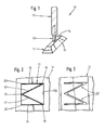
- the beacon stand 10 shown as a whole in FIG. 1 has a base plate 11, a beacon body 12 and a post 13.
- the foot plate 11 has a rectangular plan. In rough approximation it has a shape like a hipped roof with the ridge area flattened. However, it could also have any other body shape, for example that of a flat elongated cuboid.
- a recess 15 In the flat upper side 14 of the base plate 11 there is a recess 15, generally in the middle, which usually has a square outline. In some beacon stands of this type, the recess 15 is designed as a through hole, but in others as a blind hole. This recess 15 forms part of the holder for the post 13.
- the beacon body 12 is designed as a hollow body which has a lenticular or a rectangular outline at the lower end.
- the beacon body 12 has a rectangular cross-sectional shape at the upper closed end, which is generally narrower than the plan at the lower end.
- the side surfaces of the beacon body run in a continuous transition to the upper cross-sectional shape.
- the two flat side surfaces are slightly inclined towards each other.
- the beacon body 12 has a through hole in the middle of its plan area, which is matched to the shape and dimensions of the post 13. Additional guide and / or holding elements for the post 13 are present at least in the region of this through hole and / or also in the interior of the hollow body 12. Often there is also a transverse through hole in the beacon body 12 and present in the post 13, into which a holding or securing pin is inserted, through which the two parts are held together.
- the post 13 is made of metal, generally as a light metal extrusion. It has an M-profile as can be seen in FIG. 2.
- the two side webs 16 of the M-profile are aligned parallel to one another. They have the same length among themselves, which is at least approximately the same as their mutual outer distance.
- the length of the side webs 16 and their outer spacing depend on the shape and the clear width of the recess 15 in the base plate 11. If the recess 15 has a square rather than a square outline, care must be taken that the M profile of the Post 13, the side webs 16 is matched to the length of those side walls that are aligned transversely to the longitudinal extension of the foot plate 11.
- the two central webs 17 of the M-profile are arranged in a V-shape and are designed such that they extend from the connection point 18 with the respectively adjacent side web at least approximately to the middle of the connecting section of the free ends 20 of the two side webs 16. Under these conditions, it is achieved that at least the V-shaped portion of the M-profile formed by the two central webs always remains in the middle of the recess 15 because the triangle spanned by them is at their union point 19 and at the connection points 18 or at least supports the adjoining part of the two side webs 16 on the side walls of the recess 15.
- the M-profile of the post 13 is shown with sharp edges in FIG. 2.
- the profile shape can be somewhat flattened on the outside and somewhat rounded on the inside.
- the Post 13 is not made as a light metal extruded profile but as a folded profile from sheet metal, there are roundings of the M-profile at the transition points from one side web to the subsequent center web or between the two metal webs, but these should be kept as low as possible.
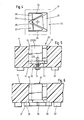
- the foot plate 21 has a recess 22 which in turn has an M-shaped outline shape as a negative shape to the M-profile of the post 13.
- This plan shape is matched to the post 13 so that the end portion of the post 13 can be inserted into the recess 16 and has a tight fit in it.
- This close coordination applies in particular to those areas of the recess 22 which accommodate the side webs 16 and middle webs 17 of the post 13.
- the recess 16 can be made with larger roundings of their outline shape in order to facilitate the insertion of a post 13.
- the very close approximation of the outline shape of the recess 16 to the M-profile of the post 13 results in a very good hold of all the profile parts of the post 13.
- a similar close guidance of the profile parts of the post 13 and the resulting good hold of the post 13 in the base plate can be achieved by inserting an adapter 23 into the recess 15, the outer shape of which and dimensions are closely matched to the shape and dimensions of the recess 15.
- This adapter 23 has a lateral recess 24 on each of two sides facing away from one another and a central recess 25 in the central region thereof They are aligned perpendicularly and merge into one another and, at least approximately, represent a negative form of the M-profile of the post 13.
- larger roundings and thus corresponding deviations of the boundary walls of the recesses 24 and 25 from the nominal geometric shape of the M-profile are possible on the inside of the transition points between two profile parts.
- the two adapter parts 26 and 27 are mirror images of one another.
- the adapter part 28 has approximately a shape which arises from an adapter parts 26 and 27 which are joined together on their back surfaces.
- the three adapter parts 26 ... 28 are made in one piece with a base plate 29 (FIG. 5).
- This base plate 29 has a plan area which is closely matched to the plan of the recess 15 of the base plate 11 and which therefore ensures that the adapter 23 fits well in the recess 15.
- a securing of the adapter 23 can be created by providing a through hole 32 in the floor area of the adapter part 28 in the bottom part 31 of the foot plate 11 which closes off the recess 15 at the bottom, that a threaded hole 33 in the form of a blind hole is present in the line of alignment in the adapter 23 and that a fastening screw 34 is inserted through the through hole 32 and screwed into the threaded hole 33.
- a modified adapter 35 shown in FIG. 6 is used. Its floor plan is the same as the adapter 23 (Fig. 4) or at least equal to the floor plan of the passage.
- the base plate 36 which unites the adapter parts to one another, is provided with a circumferential collar 37, which is already indicated by dash-dotted lines in FIG. 4. This collar 37 protrudes all over the outline of the recess 15 Aus. At least two diametrically located points, there are fastening means approximately in the form of fastening screws 38, which are indicated in FIG.
- the base plate 11 or 11 ⁇ is provided on its underside with feet 39 or 39 ⁇ , through which there is sufficient clearance for the head on the underside of the base plate the fastening screw 34 or for the collar 37 on the base plate 36 remains free. If there is no such free space, the fastening screw 34 would have to be designed as a countersunk screw or a recess should be provided on the underside of the foot plate 11 for this purpose. In a similar manner, a corresponding recess would have to be provided on the underside of the footplate 11 ⁇ for the collar 38.
- the adapter 40 for the post 13, which can be seen in FIGS. 7 and 8, is modified in some features compared to the adapter 23 (FIGS. 4 and 5).
- the continuous base plate 41 With the continuous base plate 41, the outline of which is at least approximately the same as the outline of the recess 15 of the base plate 11, the three column-like or peg-like adapter parts 42 ... 44 are formed, between which the post 13 with the M-profile can be inserted.
- the middle adapter part 42 with the outline shape of an isosceles triangle is provided on the inside with an axial recess 45 which extends from the base plate 41 to the free end face of the adapter 40 and which opens out there.
- the adapter parts 43 and 44 are each provided with a recess 46 and 47, respectively.
- the recess 45 gives the outer wall 48 of the adapter part 42 a certain elasticity in the direction of the interior of the recess 45.
- a bulge 49 is formed on the outside of the outer wall 48, which extends approximately from the base plate 41 to just below the free end face of the adapter 40 and which is designed in a ramp shape in this direction.
- the protrusion of the bulge 49 has a minimum value in the area of the base plate 41 and a maximum value in the area of the free end face facing away from it. Their cross-sectional area is arcuate, as can be seen from FIG. 8.
- the bulge 49 on the adapter part 42 acts like a wedge when the adapter 40 is inserted together with the posts 13 into the recess 15 in the footplate 11.
- the outer wall 48 is increasingly elastically deformed inwards.
- the restoring force caused thereby in the outer wall 48 acts as a clamping force between the adapter 40 and the base plate 11, the post 13 also being clamped at the same time because the adapter 12 is supported on its central webs 17.
- the clamping force generated by the bulge 49 on the outer wall 48 is sufficient to provide the adapter 40 and thus the post 13 with a firm fit in the recess 15 in the footplate 11. If this should not be sufficient due to the greater flexibility of the material of the base plate 11, the adapter parts 43 and 44 could also be provided with bulges similar to the bulges 49.
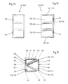
- a beacon stand 50 is explained as a further exemplary embodiment, the post of which is additionally modified.
- the reference numerals of this beacon stand 50 are increased by 40 compared to the reference numerals of the beacon stand 10 according to FIGS. 1 and 2. With this stipulation, the information on that beacon stand also applies here at least analogously.
- stiffening elements are arranged on the post 53 in a certain length section and thus at a certain height above the floor.
- one stiffening element 61 can be seen in FIGS. 9 and 10 and the two stiffening elements 62 in FIG. 11.
- the stiffening elements 61 and 62 are matched to the cavities of the M-profile of the post 53 so that they complement this profile to a full profile.
- the plan projection of the stiffening element 61 is an isosceles triangle.
- the plan projection of the two stiffening elements 62 is a right-angled triangle, which is at least approximately equal to one half of the plan projection of the stiffening element 61.
- the stiffening elements 61 and 62 are molded plastic parts.
- the stiffening element 61 has a wall 63 along the narrow side of its plan shape, a wall 64 along one of the long sides of its plan shape, and on both End faces each have a wall 65 and 66 (FIG. 13).
- the open side of the stiffening element 61 is closed by its adjacent central web 57.
- the cavity of the stiffening element 61 present within said walls is divided by a rib or by a plurality of ribs 67 and 68, which are oriented at right angles to the longitudinal extent of the stiffening element 61 and thus at the same time at right angles to the longitudinal axis of the post 53.
- the ribs 67 and 68 extend from the walls 63 and 64 to the long side of the triangular plan shape of the stiffening element 61, so that their outer edge can rest against the central web 57 of the post 53 over the entire length.
- the stiffening elements 62 have the wall 69 on their narrow side, the wall 71 on the one longitudinal side running at right angles thereto and the wall 72 and 73 on each of their end faces. Their cavity is also divided by two ribs 74 and 75, as is the case with the stiffening element 61.
- the elevation projections parallel to the wall 69 of the stiffening elements 62 thus correspond to the corresponding elevation projections of the stiffening element 61, which can be seen in FIGS. 5 and 6.
- the stiffening element 61 there are a few recesses 76 and 77 on the narrower wall 63 in the region of their end walls 65 and 66, or at least in the vicinity of the two outer edges.
- the stiffening elements 62 there are only one recess 78 or 79 on the right-angled edge. These recesses 76 ... 79 are used to fasten the stiffening elements 61 and 62 to a post 53.
- one of these recesses is provided in the area the adjacent edge of the M-profile plastically deformed a small length and thereby into the relevant recess.
- stiffening elements 61 and 62 both in the transverse direction of the Post 53 as well as in its longitudinal direction in the cavity of its M-profile.
- This attachment by positive locking has the advantage that the connection between the stiffening elements 61 and 62 and the post 53 is still ensured even if the post 53 is elastically deformed or if it experiences permanent deformations within certain limits.
- the post 53 is provided at its lower end with an adapter 81, which is designed like the adapter 40 (FIGS. 7 and 8).
- an adapter 81 which is designed like the adapter 40 (FIGS. 7 and 8).
- a cap 82 is placed, which is also designed like the adapter 40.
- This cap 82 increases the connection stiffness and bending stiffness of the upper part of the post 53. It also reduces the risk of injury which could otherwise occur when handling the post with a sharp-edged M profile.
- the adapter 81 and the cap 82 each have a columnar adapter part 85 and two columnar adapter parts 86, which are connected to one another by a base plate 83 and 84, respectively.
- the adapter 81 and the cap 82 are secured in the same way as the stiffening elements 61 and 62, by bending small lengths of the edges of the M-profile of the post 53 into corresponding recesses on the adapter 81 and on the cap 82.
Landscapes
- Engineering & Computer Science (AREA)
- Architecture (AREA)
- Civil Engineering (AREA)
- Structural Engineering (AREA)
- Road Signs Or Road Markings (AREA)
- Near-Field Transmission Systems (AREA)
- Investigating Or Analysing Materials By Optical Means (AREA)
Abstract
Bei dem Bakenständer weist die Fußplatte (11) auf ihrer Oberseite eine Ausnehmung (15) mit rechteckigem oder quadratischen Grundriß auf, in die der Pfosten (13) eingesteckt ist. Am Pfosten (13) ist entweder ein Bakenblatt befestigt oder ein Bakenkörper aufgesteckt. Der Pfosten (13) weist ein M-Profil auf, dessen beide zueinander parallelen Seitenstege (16) untereinander die gleiche Länge haben, die zumindest annähernd gleich der lichten Weite der Ausnehmung (15) in der Fußplatte (11) ist. Die beiden Mittelstege (17) des M-Profils haben untereinander ebenfalls die gleiche Länge und erstrecken sich von der Verbindungsstelle (18) mit dem jeweils benachbarten Seitensteg (16) aus zumindest annähernd bis zur Mitte (19) der Verbindungsstrecke der freien Enden (20) der beiden Seitenstege (16) des M-Profils hin.In the beacon stand, the base plate (11) has a recess (15) with a rectangular or square outline on its top, into which the post (13) is inserted. A beacon sheet is attached to the post (13) or a beacon body is attached. The post (13) has an M-profile, the two parallel side webs (16) of which are mutually parallel and have the same length, which is at least approximately equal to the inside width of the recess (15) in the footplate (11). The two central webs (17) of the M-profile also have the same length and extend from the connection point (18) with the adjacent side web (16) at least approximately to the middle (19) of the connecting section of the free ends (20) of the two side webs (16) of the M profile.
Description
Auf Straßen und Plätzen müssen immer wieder Baken der verschiedensten Art sowie Hinweisschilder, Verbotsschilder, Absperrschranken und dergleichen vorübergehend aufgestellt werden. Insbesondere an den Baustellen auf den Fernstraßen und Autobahnen werden Baken mit oder ohne zusätzliche Verkehrszeichen oder Lampen in größerer Anzahl dicht hintereinander aufgestellt, um an den vom üblichen Verkehrsweg abweichenden Streckenabschnitten ein visuell möglichst lückenlose Verkehrsführung zu schaffen. Diese Baken werden in der Regel an Bakenständern befestigt, die auch Fußplattenständer genannt werden und die eine Fußplatte, ein Bakenrohr und eine Halterung zwischen dem Bakenrohr und der Fußplatte aufweisen.On streets and squares, various types of beacons as well as information signs, prohibition signs, barriers and the like must be temporarily set up again and again. Particularly at the construction sites on the trunk roads and highways, beacons with or without additional traffic signs or lamps are placed in large numbers in close succession in order to create a route that is as visually complete as possible on the sections of the route deviating from the usual traffic route. These beacons are usually attached to beacon stands, which are also called footplate stands and which have a footplate, a beacon tube and a holder between the beacon tube and the footplate.
Bei herkömmlichen Bakenständern, insbesondere bei solchen älterer Bauart, besteht der Teil der Halterung an der Fußplatte im allgemeinen aus einer Tasche mit quadratischem Querschnitt. Sie wird bei einer metallenen Ausführung der Fußplatte durch deren Konstruktionsteile und/oder durch zusätzlich angeschweißte Stabstahlabschnitte gebildet. Bei Fußplatten aus Kunststoff und dergleichen, ist die Tasche als Ausnehmung der Oberseite der Fußplatte angeformt. Das meist runde Bakenrohr weist an seinem unteren Ende einen zur Tasche passenden Vierkantfuß auf. Zum Teil wird er durch angeschweißte Stabstahlabschnitte gebildet. Bei einer anderen Ausführungsform des Bakenrohres wird der Vierkantfuß durch ein Kunststoff-Formteil mit quaderförmiger Gestalt gebildet, das ein rundes Durchgangsrohr aufweist, in welches das Bakenrohr eingesteckt ist und meist durch einen Niet gegen verdrehen gesichert ist.In conventional beacon stands, especially those of an older type, the part of the holder on the base plate generally consists of a pocket with a square cross section. In the case of a metal version of the footplate, it is formed by its structural parts and / or by additionally welded-on steel bar sections. In the case of plastic footplates and the like, the pocket is formed as a recess in the top of the footplate. The mostly round beacon tube has a square foot that fits the bag at its lower end. In part, it is formed by welded bar sections. In another embodiment of the beacon tube, the square foot is formed by a plastic molded part with a cuboid shape, which has a round through tube into which the beacon tube is inserted and is usually secured against twisting by a rivet.
Die Bakenrohre sind im allgemeinen als verzinkte Stahlrohre ausgebildet, die aufgrund ihres Durchmessers und ihrer Wandstärke ein beträchliches Widerstandsmoment gegen Biegung haben. Wenn ein solcher Bakenständer durch ein Fahrzeug umgefahren wird, wird das Bakenrohr verbogen und meist sogar abgeknickt. Manchmal wird das Bakenrohr dabei auch aus der Fußplatte herausgerissen und weggeschleudert. In den Fällen, in denen das Bakenrohr sich in Halterung verklemmt, übt das Bakenrohr infolge seines hohen Widerstandmomentes eine Hebelwirkung auf die Fußplatte aus, so daß sie auf der Auffahrseite angehoben wird. Dabei kann sie sich in die Unterseite des darüber hinwegfahrenden Fahrzeuges hineinbohren und an der Vorderachse, vor allem an den Teilen der Lenkung und Bremsanlage, schwere Schäden anrichten. Außerdem kann das Fahrzeug dabei aus seiner Fahrtrichtung abgelenkt werden, so daß es von der Straße abkommt oder bei Gegenverkehr in diesen hineinfährt.The beacon tubes are generally designed as galvanized steel tubes which, due to their diameter and wall thickness, have a considerable moment of resistance to bending to have. If such a beacon stand is driven around by a vehicle, the beacon tube is bent and usually even kinked. Sometimes the beacon tube is torn out of the footplate and flung away. In the cases in which the beacon tube jams in the holder, the beacon tube exerts a leverage effect on the footplate due to its high resistance moment, so that it is raised on the drive-up side. It can drill into the underside of the vehicle traveling over it and cause serious damage to the front axle, especially to the parts of the steering and braking system. In addition, the vehicle can be deflected from its direction of travel, so that it comes off the road or drives into it in oncoming traffic.
Der in Anspruch 1 oder 2 angegebenen Erfindung liegt die Aufgabe zugrunde, Bakenständer so zu gestalten, daß insbesondere die Gefahr des Aufbäumens der Fußplatte beim Überfahren des Bakenständers vermindert oder beseitigt ist.The invention specified in claim 1 or 2 is based on the object of designing beacon stands in such a way that, in particular, the risk of the footplate rising up is reduced or eliminated when the beacon stand is passed over.
Dadurch das an Stelle eines Bakenrohres ein Pfosten mit einem M-Profil verwendet wird, hat dieser Pfosten für die etwa durch Windstöße oder durch die Luftstöße vorbeifahrender Fahrzeuge, ein ausreichend großes Widerstandsmoment gegen Biegung, so daß das am Pfosten befestigte Bakenblatt oder der Bakenkörper oder auch ein Verkehrszeichen seine Stellung in der richtigen Ausrichtung beibehält. Wenn ein solcher Bakenständer überfahren wird und dabei eine höhere seitliche Belastung des Pfostens entsteht, wird der Pfosten kurz oberhalb der Fußplatte verbogen. An der Biegestelle werden die teils parallel und teils schräg zueinander verlaufenden Stege des M-Profils einander genähert. Sie werden gewissermaßen zusammengefaltet. Dadurch verringert sich das Widerstansmoment des Pfostens gegen Biegung an dieser Stelle schlagartig auf einen sehr viel geringeren Wert, so daß der Pfosten mit dem Bakenblatt oder mit dem Bakenkörper praktisch wie bei einem Gelenk umklappt, ohne daß die Fußplatte dabei nennenswert aufbäumt. Damit kann das Fahrzeug ungehindert über den Bakeständer hinwegfahren, ohne daß die Gefahr besteht, daß die Fußplatte sich an der Unterseite des Fahrzeuges verhakt und/oder darin hineinbohrt. Nach einem solchen Unfall muß der Pfosten zwar ausgetauscht werden. Die Kosten dafür sind aber weit geringer als die Kosten, die bei dem Fahrzeug entstünden, wenn beim Überfahren des Bakenständers dessen Fußplatte sich aufbäumen würde und sich din die Unterseite des Fahrzeuges hineinbohren würde.Due to the fact that a post with an M-profile is used instead of a beacon tube, this post has a sufficiently high resistance to bending for the vehicles passing by, e.g. due to gusts of wind or air blows, so that the beacon sheet or the beacon body attached to the post or else a traffic sign maintains its position in the correct orientation. If such a beacon stand is run over and there is a higher lateral load on the post, the post is bent just above the footplate. At the bending point, the webs of the M-profile, which run partly parallel and partly at an angle to one another, are brought together. In a way, they are folded up. This suddenly reduces the resistance of the post to bending at this point to a much lower value, so that the post with the beacon blade or with the beacon body folds down practically like a joint, without the footplate lifting up appreciably. This allows the vehicle to drive over the bake stand unhindered without the risk of the footplate getting caught on the underside of the vehicle and / or boring into it. After such an accident, the post has to be replaced. The costs for this, however, are far lower than the costs that would arise for the vehicle if, when the beacon stand was passed over, its base plate would rise up and the inner side of the vehicle was drilled into it.
Die Ausführungsform des Bakenständers nach Anspruch 1 kommt vor allem für das Umrüsten bereits vorhandener Bakenständer in Betracht, bei dem die bisher schon vorhandenen Fußplatten weiter verwendet werden können, bis es eines Tages erforderlich wird, sie durch eine neue Fußplatte zu ersetzen, die dann eine andere Ausführungsform haben kann. Die Ausführungsform des Bakenständers nach Anspruch 2 kommt vor allem für solche Bakenständer in Betracht, bei denen also die Fußplatte ganz auf das Profil des Pfosten mit dem M-Profil abgestimmt ist.The embodiment of the beacon stand according to claim 1 is particularly suitable for converting existing beacon stands, in which the previously existing foot plates can continue to be used until one day it becomes necessary to replace them with a new foot plate, which is then another Embodiment can have. The embodiment of the beacon stand according to claim 2 is particularly suitable for those beacon stands, in which the base plate is therefore completely matched to the profile of the post with the M-profile.
Wenn ein Bakenständer der erstgenannten Ausführungsform nach Anspruch 3 ausgestaltet wird, wird durch den Adapter erreicht, daß die zwischen den einzelnen Stegen des M-Profils des Pfostens in diese Zwischenräume hineinragenden Teile des Adpaters einen zusätzlichen Halt geben. Dadurch wird außerdem erreicht, daß bei einer höheren seitlichen Belastung des Pfostens und bei einem beginnenden Biegevorgang in dem vom Adapter aufgenommenen Längenabschnitt des Pfostens dessen Stege in der vorgegebenen gegenseitigen Zuordnung und dem daraus sich ergebenden gegenseitigen Abstand gehalten werden, so daß der Pfosten nicht in der Ausnehmung der Fußplatte umknickt und dabei der Sitz des Pfostens gelockert wird, sondern daß der Pfosten im Adapter und damit in der Ausnehmung der Fußplatte festgehalten wird und der Biege- oder Abknickvorgang außerhalb der Halterung erfolgt oder der Biegevorgang seinerseits nicht durch fremde Teile gestört wird. Bei der alternativen Ausgestaltung des Bakenständers nach Anspruch 4 wird das gleiche erreicht für Pfosten bei Fußplatten mit einer nach unten durchgehenden Ausnehmung.If a beacon stand of the first-mentioned embodiment is designed according to claim 3, the adapter ensures that the parts of the adapter protruding into the spaces between the individual webs of the M-profile of the post provide additional support. This also ensures that with a higher lateral load on the post and at the beginning of a bending process in the longitudinal section of the post received by the adapter, its webs are held in the predetermined mutual assignment and the resulting mutual distance, so that the post does not move in the The footplate is recessed and the seat of the post is loosened, but that the post is held in the adapter and thus in the recess of the footplate and the bending or bending process outside the holder takes place or the bending process itself is not disturbed by foreign parts. In the alternative embodiment of the beacon stand according to claim 4, the same is achieved for posts in foot plates with a downward recess.
Bei einem nach Anspruch 5 ausgestalteten Bakenständer hat der Adapter am Fuß des Pfostens in Richtung der Auswölbung eine Abmessung, die größer als die lichte Weite der Ausnehmung in der Fußplatte ist. Dadurch, daß der Adapterteil mit der Auswölbung im inneren mit einer axialen Ausnehmung versehen ist, die an der Stirnseite offen ist, hat der Wandteil mit der Auswölbung eine erhöhte Biegeelastizität. Beim Einstecken eines Pfostens mit einem solchen Adapter wird der Wandteil mit der rampenförmigen Ausnehmung im zunehmenden Maße elastisch nach innen verformt. Die elastische Rückstellkraft dieses Wandteils bleibt anschließend ständig erhalten, so daß dieser Adapter eine beträchtliche Klemmkraft zwischen dem Pfosten und der Fußplatte ausübt. Dadurch hat ein solcher Pfosten einen sehr festen Sitz in der Fußplatte, der zusätzliche Befestigungsteile überflüssig macht, wodurch der Bakenständer nicht nur billiger wird, sondern auch schneller montiert und demontiert werden kann. Bei einer Ausgestaltung des Bakenständers nach Anspruch 6 ist eine zuverlässige dauerhafte Verbindung des Adapters mit dem Pfosten möglich, für die ebenfalls keine weiteren Befestigungsmittel erforderlich sind.In a beacon stand designed according to claim 5, the adapter at the foot of the post in the direction of the bulge has a dimension which is greater than the clear width of the recess in the footplate. Because the adapter part with the bulge is provided on the inside with an axial recess which is open on the end face, the wall part with the bulge has an increased bending elasticity. When a post is inserted with such an adapter, the wall part with the ramp-shaped recess is increasingly elastically deformed inwards. The elastic restoring force of this wall part is then constantly maintained, so that this adapter exerts a considerable clamping force between the post and the footplate. As a result, such a post has a very firm fit in the footplate, which makes additional fastening parts unnecessary, which not only makes the beacon stand cheaper, but can also be assembled and disassembled more quickly. In a configuration of the beacon stand according to claim 6, a reliable permanent connection of the adapter to the post is possible, for which no further fastening means are also required.
Bei einer Ausgestaltung des Bakenständers nach Anspruch 7, bei der in einer gewissen Entfernung oberhalb des in die Fußplatte eingesteckten Endabschnittes am Pfosten Versteifungselemente angeordnet sind, die das Endprofil des Pfostens zu einem Vollprofil ergänzen, ist in diesem Längenabschnitt das Biegemoment gegen Biegen wesentlich erhöht. Insbesondere dann, wenn ein solcher Bakenständer nach Anspruch 8 die Versteifungselemente in einem Höhebereich angebracht werden, in dem der Bakenständer üblicherweise von der Stoßstange eines auffahrenden Personenkraftwages getroffen wird, wird durch die Versteifungselemente erreicht, daß an der Auftreffstelle der Stoßstange unter ihrer Schlagwirkung nicht eine zweite Knickstelle entsteht, bei der die oberhalb der Kraftangriffsstelle befindlichen Teile des Pfostens, des Bakenblattes oder des Bakenkörpers oder eines Verkehrszeichens oder sonstiger verkehrstechnischer Teile unter der Wirkung ihrer Massenträgheitskraft gegenüber der nach vorn gerichteten Knickbewegung nicht relativ zurückbleiben und dadurch gegen das sich weiterbewegende Fahrzeug zurückschlagen und das Fahrzeug beschädigen. Eine solche Ausbildung des Bakenständers ist dann besonders vorteilhaft, wenn mit höheren Auffahrgeschwindigkeiten und daraus sich ergebender höherer Beschleunigung und infolge dessen mit höheren Massenträgheitskräften gerechnet werden muß. Bei einer Weiterbildung des Bakenständers nach Anspruch 9 lassen sich die Verstärkungselemente verhältnismäßig einfach am Pfosten befestigen, wobei auch dann noch eine dauerhafte Verbindung zwischen den Versteifungselementen und dem Pfosten gewährleistet ist, wenn der Pfosten elastisch verformt wird oder in gewissen Grenzen eine plastische Verformung erfährt.In an embodiment of the beacon stand according to claim 7, in which stiffening elements are arranged at a certain distance above the end section inserted into the base plate on the post, which complement the end profile of the post to a full profile, the bending moment against bending is significantly increased in this length section. Especially when such a beacon stand according to claim 8, the stiffening elements are mounted in a height range in which the beacon stand is usually from the bumper of a passenger car is hit, is achieved by the stiffening elements that at the point of impact of the bumper does not create a second kink under its impact, in which the parts of the post, the beacon blade or the beacon body or a traffic sign or other located above the force application point traffic engineering parts under the effect of their inertia relative to the forward bending movement do not remain relatively behind and thereby strike back against the moving vehicle and damage the vehicle. Such a design of the beacon stand is particularly advantageous when higher acceleration speeds and the resulting higher acceleration and, as a result, higher inertia forces are to be expected. In a further development of the beacon stand according to claim 9, the reinforcing elements can be relatively easily attached to the post, a permanent connection between the stiffening elements and the post being guaranteed even if the post is elastically deformed or undergoes plastic deformation within certain limits.
Durch eine Ausgestaltung des Bakenständers nach Anspruch 10 wird zwar sowohl der Formänderungswiderstand des Pfostens gegen Einbeulen und das Widerstandsmoment des Pfostens gegen Biegung stark erhöht, ohne daß dadurch aber die Masse des Pfostens in diesem Bereich sehr stark zunimmt.By an embodiment of the beacon stand according to
Durch eine Ausgestaltung des Bakenständers nach Anspruch 11 wird die Verbindungssteifigkeit des Pfostens erhöht. Zusätzlich wird die Gefahr von Verletzungen bei der Handhabung des Pfostens verringert, und zugleich das Eindrücken des Pfostens in die Ausnehmung einer Bodenplatte erleichtert, insbesondere dann wenn der Adapter nach Anspruch 5 ausgestaltet ist und eine rampenförmige Auswölbung aufweist. Wenn die Ausgestaltung des Pfostens nach Anspruch 11 der Gestalt vorgenommen wird, daß die Versteifungselemente und ihre Endplatte gleich dem Adapter in der Ausgestaltung nach Anspruch 5 ausgebildet wird, kann ein und dasselbe Kunststofformteil für beide Enden des Pfostens verwendet werden. Dadurch werden die Kosten für die Herstellung und für die Lagerhaltung dieser Teile erheblich vermindert.The connecting rigidity of the post is increased by an embodiment of the beacon stand according to
Im folgenden wird die Erfindung anhand eines in der Zeichnung dargestellten Ausführungsbeispieles näher erläutert. Es zeigen:
- Fig. 1 eine perspektivische Ansicht eines Bakenständers gemäß der Erfindung mit Fußplatte, Pfosten und Bakenkörper;
- Fig. 2 und 3 je eine Seitenansicht der quer zur Fußplatte ausgerichteten beiden Seiten des Pfostens des Bakenständers;
- Fig. 4 eine teilweise geschnitten dargestellte Draufsicht und je ein Horizontalschnitt dreier Versteifungselemente des Pfostens;
- Fig. 5 und 6 je eine Seitenansicht des mittleren Versteifungselementes nach Fig. 4;
- Fig. 7 einen Vertikalschnitt einer weiteren abgewandelten Ausführungsform des Adapters nach der Schnittverlaufslinie VII - VII in Fig. 8;
- Fig. 8 eine Draufsicht des Adapters nach Fig. 7 mit einem Horizontalschnitt des zugehörigen Pfostens
- Fig. 9 eine perspektivische Ansicht eines abgewandelten Ausführungsbeispieles des Bakenständers;
- Fig. 10 und 11 je eine Seitenansicht der quer zur Fußplatte ausgerichteten beiden Seiten des Pfostens nach Fig. 9;
- Fig. 12 eine teilweise geschnitten dargestellte Draufsicht und je ein Horizontalschnitt dreier Versteifungselemente des Pfostens nach Fig. 9;
- Fig. 13 und 14 je eine Seitenansicht des mittleren Versteifungs elementes nach Fig. 12.
- Figure 1 is a perspective view of a beacon stand according to the invention with a base plate, post and beacon body.
- 2 and 3 each show a side view of the two sides of the post of the beacon stand aligned transversely to the base plate;
- 4 is a top view, partly in section, and a horizontal section of three stiffening elements of the post;
- 5 and 6 each show a side view of the middle stiffening element according to FIG. 4;
- 7 shows a vertical section of a further modified embodiment of the adapter along the section line VII - VII in FIG. 8;
- Fig. 8 is a plan view of the adapter of FIG. 7 with a horizontal section of the associated post
- 9 is a perspective view of a modified embodiment of the beacon stand;
- 10 and 11 each show a side view of the two sides of the post according to FIG. 9 aligned transversely to the base plate;
- FIG. 12 shows a top view, partly in section, and a horizontal section of three stiffening elements of the post according to FIG. 9;
- 13 and 14 are each a side view of the central stiffening element of FIG .. 12
Der aus Fig. 1 als Ganzes ersichtliche Bakenständer 10 weist eine Fußplatte 11, einen Bakenkörper 12 und einen Pfosten 13 auf.The beacon stand 10 shown as a whole in FIG. 1 has a
Die Fußplatte 11 hat einen rechteckigen Grundriß. Sie hat in grober Näherung eine Form wie ein Walmdach, bei dem der Firstbereich abgeflacht ist. Sie könnte aber auch jede andere Körperform, beispielsweise die eines flachen langgestreckten Quaders, haben. In der ebenen Oberseite 14 der Fußplatte 11 ist - im allgemeinen in der Mitte - eine Ausnehmung 15 vorhanden, die meistens einen quadratischen Grundriß hat. Bei manchen Bakenständern dieser Art ist die Ausnehmung 15 als Durchgangsloch, bei anderen jedoch als Sackloch ausgebildet. Diese Ausnehmung 15 bildet einen Teil der Halterung für den Pfosten 13.The
Der Bakenkörper 12 ist als Hohlkörper ausgebildet, der am unteren Ende einen linsenförmige oder einen rechteckigen Grundriß aufweist. Der Bakenkörper 12 hat am oberen geschlossenen Ende eine rechteckige Querschnittsform, die im allgemeinen schmäler als der Grundriß am unteren Ende ist. Bei der Ausführungsform mit einem unteren linsenförmigen Grundriß, verlaufen die Seitenflächen des Bakenkörpers in einem stetigen Übergang zur oberen Querschnittsform hin. Bei der Ausführungsform mit rechteckiger unterer Grundrißfläche sind die beiden ebenen Seitenflächen leicht gegeneinander geneigt.The
Am unteren Ende weist der Bakenkörper 12 in der Mitte seiner Grundrißfläche ein Durchgangsloch auf, das auf die Form und Abmessungen des Pfostens 13 abgestimmt sind. Zumindest im Bereich dieses Durchgangsloches und/oder auch im Inneren des hohlen Bakenkörpers 12 sind zusätzliche Führungs- und/oder Halteelemente für den Pfosten 13 vorhanden. Häufig ist auch ein quer verlaufendes Durchgangsloch im Bakenkörper 12 und im Pfosten 13 vorhanden, in das ein Halte- oder Sicherungsstift eingesetzt wird, durch das die beiden Teile aneinander festgehalten werden.At the lower end, the
Der Pfosten 13 ist aus Metall hergestellt, und zwar im allgemeinen als Leichtmetall-Strangpreßprofil. Er hat ein M-Profil wie aus Fig. 2 ersichtlich ist. Die beiden Seitenstege 16 des M-Profils sind zueinander parallel ausgerichtet. Sie haben untereinander die gleiche Länge, die zumindest annähernd gleich ihrem gegenseitigen Außenabstand ist. Die Länge der Seitenstege 16 und ihr Außenabstand richten sich nach der Form und der lichten Weite der Ausnehmung 15 in der Fußplatte 11. Falls die Ausnehmung 15 nicht einen quadratischen sondern einen rechteckigen Grundriß hat, ist darauf zu achten, daß bei dem M-Profil des Pfostens 13 die Seitenstege 16 auf die Länge derjenigen Seitenwände abgestimmt ist, die quer zur Längserstreckung der Fußplatte 11 ausgerichtet sind. Die beiden Mittelstege 17 des M-Profils sind V-förmig angeordnet und so ausgebildet, daß sie sich von der Verbindungsstelle 18 mit dem jeweils benachbarten Seitensteg aus zumindest annähernd bis zu der Mitte der Verbindungsstrecke der freien Enden 20 der beiden Seitenstege 16 erstrecken. Unter diesen Voraussetzungen wird erreicht, daß zumindest der durch die beiden Mittelstege gebildete V-förmige Teilbereich des M-Profils stets in der Mitte der Ausnehmung 15 bleibt, weil das von ihnen aufgespannte Dreieck sich an ihrer Vereinigungsstelle 19 und an den Verbindungsstellen 18 oder zumindest an dem daran anschließenden Teil der beiden Seitenstege 16 an den Seitenwänden der Ausnehmung 15 abstützt.The
Das M-Profil des Pfostens 13 ist in Fig. 2 scharfkantig dargestellt. Insbesondere bei der Vereinigungsstelle 19 der beiden Mittelstege 17 kann die Profilform auf der Außenseite etwas abgeflacht und auf der Innenseite etwas abgerundet sein. Ähnliches gilt für die Verbindungsstellen 18 zwischen je einem Seitensteg 16 und je einem Mittelsteg 17. Falls der Pfosten 13 nicht als Leichtmetall-Strangpreßprofil sondern als Abkantprofil aus Metallblechen hergestellt wird, ergeben sich an den Übergangsstellen vom einen Seitensteg zum anschließenden Mittelsteg oder zwischen den beiden Metallstegen von selbst Abrundungen des M-Profils, die aber so gering wie möglich gehalten werden sollen.The M-profile of the
Bei der aus Fig. 3 ausschnittweise ersichtlichen abgewandelten Ausführungsform des Bakenständer weist die Fußplatte 21 eine Ausnehmung 22 auf, die ihrerseits eine M-förmige Grundrißform als Negativform zum M-Profil des Pfostens 13 hat. Diese Grundrißform ist auf den Pfosten 13 so abgestimmt, daß der Endabschnitt des Pfostens 13 in die Ausnehmung 16 eingesteckt werden kann und darin einen möglichst festen Sitz hat. Diese enge Abstimmung gilt insbesondere für diejenigen Bereiche der Ausnehmung 22, die die Seitenstege 16 und Mittelstege 17 des Pfostens 13 aufnehmen. An den Verbindungsstellen 18 zwischen einem Seitensteg 16 und dem benachbarten Mittelsteg 17 sowie an der Vereinigungsstelle 19 der beiden Mittelstege 17 kann die Ausnehmung 16 mit größeren Abrundungen ihrer Grundrißform ausgeführt werden, um das Einsetzen eines Pfosten 13 zu erleichtern. Insgesamt ergibt die sehr weitgehende Annäherung der Grundrißform der Ausnehmung 16 an das M-Profil des Pfostens 13 einen sehr guten Halt sämtlicher Profilteile des Pfostens 13.In the modified embodiment of the beacon stand, which can be seen in detail from FIG. 3, the
Bei Fußplatten mit einer quadratischen oder rechteckigen Grundrißform, kann eine ähnliche enge Führung der Profilteile des Pfostens 13 und der daraus sich ergebende gute Halt des Pfostens 13 in der Fußplatte dadurch erreicht werden, daß ein Adapter 23 in die Ausnehmung 15 eingesetzt wird, dessen äußere Form und Abmessungen auf die Form und die Abmessungen der Ausnehmung 15 eng abgestimmt sind. Dieser Adapter 23 weist an zwei voneinander abgekehrten Seiten je eine seitliche Ausnehmung 24 und in seinem mittleren Bereich je eine mittlere Ausnehmung 25 auf, die lotrecht ausgerichtet sind die ineinander übergehen und die zumindest nährungsweise eine Negativform des M-Profils des Pfostens 13 darstellen. Dabei sind, wie zuvor schon erwähnt, auf den Innenseiten der Übergangsstellen zwischen zwei Profilteilen größere Abrundungen und damit entsprechende Abweichungen der Begrenzungswände der Ausnehmungen 24 und 25 gegenüber der geometrischen Sollform des M-Profils möglich.In the case of base plates with a square or rectangular outline shape, a similar close guidance of the profile parts of the
Außerhalb der Grundrißflächen der Ausnehmungen 24 und 25 und innerhalb der Umrißlinien der Ausnehmung 15 der Fußplatte 11 verbleiben am Adapter 23 drei säulenartige oder zapfenartige Adapterteile 26 ... 28 mit dreiecksförmiger Grundrißfläche. Die beiden Adapterteile 26 und 27 sind einander spiegelbildlich gleich. Der Adapterteil 28 hat näherungsweise eine Gestalt, die aus einer an ihren Rückenflächen miteinander vereinigten Adapterteilen 26 und 27 hervorgeht.Outside the plan areas of the
Die drei Adapterteile 26 ... 28 sind zusammen mit einer Bodenplatte 29 einstückig hergestellt (Fig. 5). Diese Bodenplatte 29 hat eine Grundrißfläche, die eng auf den Grundriß der Ausnehmung 15 der Fußplatte 11 abgestimmt ist und die daher für einen guten Sitz des Adapters 23 in der Ausnehmung 15 sorgt. Zusätzlich kann eine Sicherung des Adapters 23 dadurch geschaffen werden, daß im Grundrißbereic des Adapterteils 28 in dem die Ausnehmung 15 unten abschließenden Bodenteil 31 der Fußplatte 11 ein Durchgangsloch 32 vorhanden ist, daß in dessen Fluchtlinie im Adapter 23 ein Gewindeloch 33 in Form eines Sackloches vorhanden ist, und daß eine Befestigungsschraube 34 durch das Durchgangsloch 32 hindurchgesteckt und in das Gewindeloch 33 eingeschraubt ist.The three
Bei Fußplatten 11ʹ, bei denen die Ausnehmung 15ʹ für den Pfosten 13 als Durchgangsloch ausgebildet ist oder bei denen ein sonstiger größerer Durchgang vorhanden ist, wird ein aus Fig. 6 ersichtlicher abgewandelter Adpater 35 verwendet. Sein Grundriß ist gleich dem Adapter 23 (Fig. 4) oder zumindest gleich dem Grundriß des Durchganges. Bei ihm ist die die Adapterteile miteinander vereinigende Bodenplatte 36 mit einem umlaufenden Kragen 37 versehen, der in Fig. 4 strichpunktiert bereits angedeutet ist. Dieser Kragen 37 ragt ringsum über die Umrißlinie der Ausnehmung 15ʹ hinaus. An wenigstens zwei diametral gelegenen Stellen sind Befestigungsmittel etwa in Form von Befestigungsschrauben 38 vorhanden, die in Fig. 6 lediglich durch eine Strichpunktlinie angedeutet sind und die durch ein entsprechendes Durchgangsloch im Kragen 37 hindurchgesteckt und in ein Gewindesackloc auf der Unterseite der Fußplatte 11ʹ eingeschraubt sind. Dadurch wird sichergestellt, daß der Adapter 35 beim Einstecken eines Pfostens 13 nicht aus Versehen nach unten herausgestoßen wird, falls sein Sitz in der Ausnehmung 15ʹ, aus welchen Gründen auch immer, nicht sehr stramm sein sollte.In the case of base plates 11ʹ, in which the recess 15ʹ for the
Bei den Ausführungsformen des Bakenständers 10 mit einem Adapter gemäß Fig. 5 oder 6 wurde angenommen, daß die Fußplatte 11 bzw. 11ʹ auf ihrer Unterseite mit Füßen 39 bzw. 39ʹ versehen ist, durch die auf der Unterseite der Fußplatte ein ausreichender Freiraum für den Kopf der Befestigungsschraube 34 bzw. für den Kragen 37 an der Bodenplatte 36 frei bleibt. Falls ein solcher Freiraum nicht vorhanden ist, müßte die Befestigungsschraube 34 als Senkkopfschraube ausgebildet werden oder dafür eine Ausnehmung an der Unterseite der Fußplatte 11 vorgesehen werden. In ähnlicher Weise müßte für den Kragen 38 eine entsprechende Ausnehmung auf der Unterseite der Fußplatte 11ʹ vorgesehen werden. Im letztgenannten Falle würde es auch genügen, wenn an Stelle eines umlaufenden Kragens 37 einzelne Kragenabschnitte, die dann mehr die Form von Lappen haben, am Adapter 35 angeformt werden, die auf der Unterseite der Fußplatte 11ʹ in Ausnehmungen hineinpassen, die eine nur wenig größere Grundrißfläche als die Lappen aufweisen.In the embodiments of the beacon stand 10 with an adapter according to FIG. 5 or 6, it was assumed that the
Der aus Fig. 7 und 8 ersichtliche Adapter 40 für den Pfosten 13 ist gegenüber dem Adapter 23 (Fig. 4 und 5) in einigen Merkmalen abgewandelt. Mit der durchgehenden Bodenplatte 41, deren Grundrißform zumindest annähernd gleich der Grundrißform der Ausnehmung 15 der Fußplatte 11 ist, sind die drei säulenartigen oder zapfenartigen Adapterteile 42 ... 44 angeformt, zwischen die der Pfosten 13 mit dem M-Profil eingesteckt werden kann. Der mittlere Adapterteil 42 mit der Grundrißform eines gleichschenkligen Dreiecks ist im Inneren mit einer axialen Ausnehmung 45 versehen, die sich von der Bodenplatte 41 aus bis zur freien Stirnseite des Adapters 40 erstreckt und die dort frei mündet. In gleicher Weise sind die Adapterteile 43 und 44 mit je einer Ausnehmung 46 bzw. 47 versehen.The
Durch die Ausnehmung 45 erhält die Außenwand 48 des Adapterteils 42 eine gewisse Elastizität in Richtung auf das Innere der Ausnehmung 45 hin. Auf der Außenseite der Außenwand 48 ist eine Auswölbung 49 angeformt, die sich etwa von der Bodenplatte 41 aus bis knapp unterhalb der freien Stirnseite des Adapters 40 hin erstreckt und die in dieser Richtung rampenförmig ausgebildet ist. Der Überstand der Auswölbung 49 hat im Bereich der Bodenplatte 41 einen Kleinstwert und im Bereich der davon abgekehrten freien Stirnseite einen Größtwert. Ihre Querschnittsfläche verläuft bogenförmig, wie aus Fig. 8 ersichtlich ist.The
Die Auswölbung 49 am Adapterteil 42 wirkt wie ein Keil, wenn der Adapter 40 zusammen mit den Pfosten 13 in die Ausnehmung 15 der Fußplatte 11 eingesteckt wird. In dem Maße, in dem der Adapter 40 tiefer in die Ausnehmung 15 hineingeschoben wird, verformt sich die Außenwand 48 in zunehmendem Maße elastisch nach innen. Die dadurch in der Außenwand 48 hervorgerufene Rückstellkraft wirkt als Klemmkraft zwischen dem Adapter 40 und der Fußplatte 11, wobei zugleich auch der Pfosten 13 festgeklemmt wird, weil sich der Adapter 12 an seinen Mittelstegen 17 abstützt.The
Im allgemeinen ist die durch die Auswölbung 49 an der Außenwand 48 erzeugte Klemmkraft ausreichend, um dem Adapter 40 und damit dem Pfosten 13 einen festen Sitz in der Ausnehmung 15 der Fußplatte 11 zu verschaffen. Falls das wegen größerer Nachgiebigkeit des Werkstoffes der Fußplatte 11 einmal nicht ausreichen sollte, könnten auch die Adapterteile 43 und 44 mit ähnlichen Auswölbungen wie die Auswölbungen 49 versehen werden.In general, the clamping force generated by the
Anhand Fig. 9 ... 14 wird als weiteres Ausführungsbeispiel ein Bakenständer 50 erläutert, dessen Pfosten zusätzlich abgewandelt ist. Die Bezugszeichen dieses Bakenständers 50 sind gegenüber den Bezugszeichen des Bakenständers 10 nach Fig. 1 und 2 um 40 erhöht sind. Mit dieser Maßgabe gelten die Angaben zu jenem Bakenständer zumindest sinngemäß auch hier.9 ... 14, a
Wie in Fig. 9 bereits angedeutet ist, sind am Pfosten 53 in einem gewissen Längenabschnitt und damit in einer gewissen Höhe über dem Boden Versteifungselemente angeordnet. Davon sind in Fig. 9 und 10 das eine Versteifungselement 61 und in Fig. 11 die beiden Versteifungselemente 62 zu sehen.As already indicated in FIG. 9, stiffening elements are arranged on the
Wie in Fig. 12 angedeutet ist, sind die Versteifungselemente 61 und 62 so auf die Hohlräume des M-Profils des Pfostens 53 abgestimmt, daß sie dieses Profil zu einem Vollprofil ergänzen. Die Grundrißprojektion des Versteifungselementes 61 ist ein gleichschenkeliges Dreieck. Die Grundrißprojektion der beiden Versteifungselemente 62 ist ein rechtwinkliges Dreieck, die zumindest näherungsweise gleich der einen Hälfte der Grundrißprojektion des Versteifungselementes 61 ist.As indicated in Fig. 12, the
Die Versteifungselemente 61 und 62 sind Kunststofformteile. Das Versteifungselement 61 weist entlang der Schmalseite seiner Grundrißform eine Wand 63, entlang einer der Längsseiten seiner Grundrißform eine Wand 64 und an beiden Stirnseiten je eine Wand 65 und 66 (Fig. 13) auf. Die offene Seite des Versteifungselementes 61 wird nach dem Anbringen an einem Pfosten 53 durch dessen benachbarten Mittelsteg 57 verschlossen. Der innerhalb der genannten Wände vorhandene Hohlraum des Versteifungselementes 61 wird durch eine Rippe oder durch mehrere Rippen 67 und 68 unterteilt, die rechtwinklig zur Längserstreckung des Versteifungselementes 61 und damit zugleich rechtwinklig zur Längsachse des Pfostens 53 ausgerichtet sind. Die Rippen 67 und 68 erstrecken sich von den Wänden 63 und 64 bis an die Längsseite der dreieckigen Grundrißform des Versteifungselementes 61 hin, so daß ihr Außenrand auf der ganzen Länge am Mittelsteg 57 des Pfosten 53 anliegen kann.The
Die Versteifungselemente 62 weisen an ihrer schmalen Seite die Wand 69, an der rechtwinklig dazu verlaufenden einen Länsseite die Wand 71 und an ihren Stirnseiten je eine Wand 72 bzw. 73 auf. Ihr Hohlraum wird ebenfalls durch zwei Rippen 74 und 75 unterteilt, wie das bei dem Versteifungselement 61 der Fall ist. Die Aufrißprojektionen parallel zur Wand 69 der Versteifungselemente 62 gleichen somit den entsprechenden Aufrißprojektionen des Versteifungselementes 61, die aus Fig. 5 und 6 ersichtlich sind.The
Beim Versteifungselement 61 sind an der schmäleren Wand 63 im Bereich ihrer stirnseitigen Wände 65 und 66, oder zumindest in deren Nähe im Bereich der beiden Außenkanten je ein paar Ausnehmungen 76 bzw. 77 vorhanden. Bei den Versteifungselementen 62 befinden sich lediglich an der rechtwinkligen Kante je eine Ausnehmung 78 bzw. 79. Diese Ausnehmungen 76 ... 79 dienen der Befestigung der Versteifungselemente 61 und 62 an einem Pfosten 53. Zu diesem Zweck wird im Bereich je eine dieser Ausnehmungen von der benachbarten Kante des M-Profils ein kleiner Längenabschnitt plastisch verformt und dabei in die betreffende Ausnehmung hinein. Dadurch werden die Versteifungselemente 61 und 62 sowohl in der Querrichtung des Pfostens 53 wie auch in seiner Längsrichtung in dem betreffenden Hohlraum seines M-Profils festgehalten. Diese Befestigung durch Formschluß hat den Vorteil, daß die Verbindung zwischen den Versteifungselementen 61 und 62 und dem Pfosten 53 auch dann noch gewährleistet ist, wenn der Pfosten 53 elastisch verformt wird oder wenn er innerhalb gewisser Grenzen bleibende Verformungen erfährt.In the case of the stiffening
Wie aus Fig. 10 und 11 ersichlich ist, ist der Pfosten 53 an seinem unteren Ende mit einem Adapter 81 versehen, der gleich dem Adapter 40 (Fig. 7 und 8) ausgebildet ist. Am oberen Ende des Pfostens 53 ist eine Kappe 82 aufgesetzt, die ebenfalls gleich dem Adapter 40 ausgebildet ist. Diese Kappe 82 erhöht die Verbindungssteifigkeit und Biegesteifigkeit des oberen Teils des Pfostens 53. Außerdem verringert sie die Verletzungsgefahr, die sonst beim Handhaben des Pfostens mit scharfkantig endendem M-Profil auftreten könnte. Der Adapter 81 und die Kappe 82 weisen, wie der Adapter 40, je ein säulenförmiges Adapterteil 85 und zwei säulenförmige Adapterteile 86 auf, die durch eine Bodenplatte 83 bzw. 84 miteinander verbunden sind. Der Adapter 81 und die Kappe 82 sind in der gleichen Weise wie die Versteifungselemente 61 und 62 gesichert, indem kleine Längenabschnitte der Kanten des M-Profils des Pfostens 53 in entsprechenden Ausnehmungen am Adapter 81 und an der Kappe 82 hineingebogen werden.As can be seen from FIGS. 10 and 11, the
Claims (11)
gekennzeichnet durch die Merkmale:
- der Pfosten (13) weist ein M-Profil auf,
- die beiden Seitenstege (16) des M-Profils haben untereinander die gleiche Länge, die zumindest annähernd gleich der lichten Weite der Ausnehmung (15) entlang der beiden Seitenwände ist, die quer zur Längserstreckung der Fußplatte (11) ausgerichtet sind,
- die beiden Mittelstege (17) des M-Profils haben untereinander die gleiche Länge und erstrecken sich von der Verbindungsstelle (18) mit dem benachbarten Seitensteg (16) aus, zumindest annähernd bis zu der Mitte der Verbindungsstrecke der freien Enden (20) der beiden Seitenstege (16) des M-Profils.1. beacon stand with a base plate which has at least on its upper side a recess with a rectangular or square plan projection for a post, with a post made of metal or a tough plastic, the lower end of which fits into the recess in the base plate, and with a beacon sheet, that can be connected to the post or to a beacon body that can be plugged onto and / or connected to the post,
characterized by the features:
- The post (13) has an M-profile,
- The two side webs (16) of the M-profile have the same length, which is at least approximately equal to the inside width of the recess (15) along the two side walls, which are oriented transversely to the longitudinal extension of the footplate (11),
- The two central webs (17) of the M-profile have the same length and extend from the connection point (18) with the adjacent side web (16), at least approximately to the middle of the connecting path of the free ends (20) of the two Side bars (16) of the M-profile.
gekennzeichnet durch die Merkmale:
- der Pfosten (13) weist ein M-Profil auf,
- die beiden Seitenstege (16) des M-Profils sind zueinander parallel ausgerichtet und haben untereinander die gleiche Länge, die zumindest annähernd gleich dem Außenabstand der beiden Seitenstege (16) ist oder um eine bestimmtes Maß größer oder kleiner ist,
- die beiden Mittelstege (17) des M-Profils haben untereinander die gleiche Länge und erstrecken sich von der Verbindungsstelle (18) mit dem benachbarten Seitensteg (16) aus zumindest annähernd bis zu der Mitte der Verbindungsstrecke der freien Enden (20) der beiden Seitenstege (16) des M-Profils.
- die Ausnehmung (22) in der Fußplatte (21) hat eine Querschnittsform, die zumindest in Teilbereichend der Seitenstege (16) und der Mittelstege (17) des M-Profils des Pfostens bis an die Grundrißprojektion des M-Profils des Pfostens heranreicht oder höchstens einen geringen Abstand davon einhält.2. Beacon stand with a foot plate, which has a recess for a post at least on its top, with a post made of metal or a tough plastic, the lower end of which fits into the recess in the foot plate, and with a beacon sheet which can be connected to the post or with a beacon body that can be plugged onto and / or connected to the post,
characterized by the features:
- The post (13) has an M-profile,
- The two side webs (16) of the M-profile are aligned parallel to one another and have the same length, which is at least approximately the same as the outside distance of the two side webs (16) or is larger or smaller by a certain amount,
- The two central webs (17) of the M-profile have the same length and extend from the connection point (18) with the adjacent side web (16) at least approximately to the middle of the connecting section of the free ends (20) of the two side webs (16) of the M profile.
- The recess (22) in the base plate (21) has a cross-sectional shape that reaches at least in partial areas of the side webs (16) and the central webs (17) of the M-profile of the post up to the plan projection of the M-profile of the post or at most keep a short distance from it.
gekennzeichnet durch die Merkmale:
- es ist ein Adapter (23) vorhanden, der zumindest in einem gewissen Bereich seiner Höhen an zumindest einzelnen Umfangsstellen auf die lichte Querschnittsform der Ausnehmung (15) in der Fußplatte (11) abgestimmt ist,
- der Adapter (23) weist in seinem oberen Bereich lotrecht ausgerichtete. ineinander übergehende Ausnehmungen (24; 25) auf, deren Grundrißprojektion auf die Grundrißprojektion des M-Profils des Pfosten (13) abgestimmt ist und deren lichte Weite gleich oder geringfügig größer als die entsprechenden Abmessungen des M-Profils des Pfosten (13) ist, - vorzugsweise sind Befestigungsemelente (34) vorhanden, mittels der der Adapter (23) und die Fußplatte (11) miteinander verbindbar sind.3. Beacon stand according to claim 1
characterized by the features:
there is an adapter (23) which is matched to the clear cross-sectional shape of the recess (15) in the footplate (11) at least in a certain range of its heights at at least individual circumferential locations,
- The adapter (23) has vertically aligned in its upper region. recesses (24; 25) which merge into one another, the plan projection of which is coordinated with the plan projection of the M-profile of the post (13) and the clear width of which is the same or slightly larger than the corresponding dimensions of the M-profile of the post (13), there are preferably fastening elements (34) by means of which the adapter (23) and the base plate (11) can be connected to one another.
gekennzeichnet durch die Merkmale:
- es ist ein Adapter (35) vorhanden, dessen Außenform auf den Durchgang (15ʹ) in der Fußplatte (11ʹ) abgestimmt ist,
- der Adapter (35) weist in seinem oberen Bereich lotrecht ausgerichtete, ineinander übergehende Ausnehmungen (24; 25) auf, deren Grundrißprojektion auf die Grundrißprojektion des M-Profils des Pfostens (13) abgestimmt ist und deren lichte Weite gleich oder geringfügig größer als die entsprechenden Abmessungen des M-Profils des Pfosten (13) ist,
- der Adapter (13) weist an seinem unteren Ende einzelne Kragenabschnitte oder einen umlaufenden Kragen (37) auf, dessen Grundrißprojektion über die Grundrißprojektion der Ausnehmung (15ʹ) an der Unterseite der Fußplatte (11ʹ) hinausragt,
- der Adapter (35) und die Fußplatte (11ʹ) weisen vorzugsweise im Bereich des Kragens (37) Befestigungselemente (38) auf, mittels der der Adapter (35) und die Fußplatte (11ʹ) miteinander verbindbar sind.4. beacon stand according to claim 1, wherein the recess in the footplate has at least in a partial area of its plan projection a downwardly open passage,
characterized by the features:
- There is an adapter (35), the outer shape of which is matched to the passage (15ʹ) in the footplate (11ʹ),
- The adapter (35) has in its upper area vertically aligned, merging recesses (24; 25), the plan projection of which is coordinated with the plan projection of the M-profile of the post (13) and whose clear width is the same or slightly larger than that corresponding dimensions of the M-profile of the post (13),
- The adapter (13) has at its lower end individual collar sections or a circumferential collar (37), the floor plan projection of which extends beyond the floor plan projection of the recess (15ʹ) on the underside of the footplate (11ʹ),
- The adapter (35) and the footplate (11ʹ) preferably have fastening elements (38) in the region of the collar (37), by means of which the adapter (35) and the footplate (11ʹ) can be connected to one another.
gekennzeichnet durch die Merkmale:
- es ist ein Adapter (40) vorhanden, der zumindest in einem gewissen Bereich seiner Höhe an zumindest einzelnen Umfangsstellen auf die lichte Querschnittsform der Ausnehmung (15) in der Fußplatte (11) abgestimmt ist,
- der Adapter (40) weist in seinem oberen Bereich lotrecht ausgerichtete, ineinander übergehende Ausnehmungen auf, deren Grundrißprojektion auf die Grundrißprojektion des M-Profils des Pfostens (13) abgestimmt ist, und deren lichte Weite gleich oder geringfügig größer als die entsprechenden Abmessungen des M-Profils des Pfostens (13) ist,
- von den durch die Ausnehmungen voneinander getrennten zapfenförmigen Adapterteilen (42; 43; 44) ist zumindest der in der Symmetrieebene gelegene Adapterteil (42) im Inneren mit einer axialen Ausnehmung (45) versehen, die an der Stirnseite des Adapterteils (42) offen ist,
- auf der vom Pfosten (13) abgekehrten Außenseite (48) des Adapterteils (42) ist eine Auswölbung (49) angeformt, die über die umhüllende Quaderform des Adapters (40) nach außen hervorsteht,
- die Auswölbung (49) ist vorzugsweise rampenförmig ausgebildet, wobei ihr Überstand über die umhüllende Quaderform im Bereich des außerhalb der Ausnehmungen verbleibenden durchgehenden Bodenplatte (41) des Adapters (40) einen Kleinstwert und im Bereich der von der Bodenplatte (41) abgekehrten Stirnseite einen Größtwert hat.5. beacon stand according to claim 1,
characterized by the features:
there is an adapter (40) which is matched to the clear cross-sectional shape of the recess (15) in the footplate (11) at least in a certain area of its height at at least individual circumferential locations,
- The adapter (40) has in its upper area vertically aligned, merging recesses, the plan projection of which is coordinated with the plan projection of the M-profile of the post (13), and the clear width is the same or slightly larger than the corresponding dimensions of the M Profile of the post (13),
- Of the pin-shaped adapter parts (42; 43; 44) separated from one another by the recesses, at least the adapter part (42) located in the plane of symmetry is provided on the inside with an axial recess (45) which is open on the end face of the adapter part (42) ,
a bulge (49) is formed on the outside (48) of the adapter part (42) facing away from the post (13), which protrudes outwards beyond the cuboid shape of the adapter (40),
- The bulge (49) is preferably ramp-shaped, its protrusion over the enveloping cuboid shape in the area of the continuous bottom plate (41) of the adapter (40) remaining outside the recesses, a minimum value and in the area of the end face facing away from the bottom plate (41) Greatest value.
gekennzeichnet durch das Merkmal:
- der Adapter (40) weist in dem an die Bodenplatte (41) anschließenden Bereich seiner Höhe zumindest an einem Teil der Außenkanten seiner Quaderform Ausnehmungen auf, in die ein Endabschnitt der Seitenstege (16), vorzugsweise im Bereich der freien Längskante (20) und/oder der Verbindungskante (18) mit einem der Mittelstege (17), hineinverformbar ist.6. Beacon stand according to one of claims 3 to 5,
characterized by the characteristic:
- The adapter (40) has in the region of its height adjoining the base plate (41) at least at some of the outer edges of its cuboid shape, recesses into which an end section of the side webs (16), preferably in the region of the free longitudinal edge (20) and / or the connecting edge (18) with one of the central webs (17) is deformable.
gekennzeichnet durch das Merkmal:
- in einem bestimmten Längenabschnitt des Pfostens (53) in einer gewissen Entfernung oberhalb seines in die Fußplatte (51) eingesteckten Endabschnittes sind Versteifungselelmente (61; 62) vorhanden, die in die Hohlräume seines M-Profils eingepaßt sind und dieses zu einem quaderförmigen Vollprofil ergänzen.7. beacon stand according to one of claims 1 to 6,
characterized by the characteristic:
- In a certain length section of the post (53) at a certain distance above its end section inserted into the base plate (51) there are stiffening elements (61; 62) which are fitted into the cavities of its M-profile and complement this to form a cuboid full profile .
gekennzeichnet durch das Merkmal:
- die Versteifungselemente (61; 62) sind in einem Bereich der Höhe des Pfostens (53) angeordnet, der zumindest annähernd in dem üblichen Höhenbereich der Stoßstangen von Kraftfahrzeugen, insbesondere von Personenkraftwagen, gelegen ist.8. beacon stand according to claim 9,
characterized by the characteristic:
- The stiffening elements (61; 62) are arranged in a region of the height of the post (53) which is at least approximately in the usual height range of the bumpers of motor vehicles, in particular of passenger cars.
gekennzeichnet durch das Merkmal:
- die Versteifungselemente (61; 62) weisen vorzugsweise im Bereich ihrer Stirnseiten (25, 26; 32, 33) Ausnehmungen (36, 37; 38, 39) auf, in die kleine Längenabschnitte der ihnen benachbarten Längskante (58; 60) der Seitenstege (56; 57) des Pfostens (53) hineinverformbar sind.9. beacon stand according to claim 7 or 8,
characterized by the characteristic:
- The stiffening elements (61; 62) preferably have recesses (36, 37; 38, 39) in the region of their end faces (25, 26; 32, 33), into the small longitudinal sections of the adjacent longitudinal edge (58; 60) of the side webs (56; 57) of the post (53) are deformable.
gekennzeichnet durch die Merkmale:
- die Versteifungselement (61; 62) weisen in ihrer Längsrichtung verlaufende Hohlräume auf,
- vorzugsweise sind in den Hohlräumen Versteifungsrippen (27, 28; 34, 35) eingeformt, die bevorzugt rechtwinklig zur Längsachse des Pfostens (53) ausgerichtet sind.10. Beacon stand according to one of claims 7 to 9,
characterized by the features:
- The stiffening element (61; 62) have cavities running in their longitudinal direction,
- Stiffening ribs (27, 28; 34, 35) are preferably formed in the cavities and are preferably oriented at right angles to the longitudinal axis of the post (53).
gekennzeichnet durch die Merkmale:
- an dem vom Einsteckende abgekehrten oberen Ende des Pfostens (51) sind Versteifungselemente (82) angeordnet,
- vorzugsweise sind diese Versteifungselemente (82) an ihrer am Ende des Pfostens (53) gelegenen Stirnseite durch eine gemeinsame Endplatte (41) miteinander verbunden, die bevorzugt an ihnen einstückig angeformt ist.11. Beacon stand according to one of claims 1 to 10,
characterized by the features:
- Stiffening elements (82) are arranged on the upper end of the post (51) facing away from the insertion end,
- These stiffening elements (82) are preferably connected to one another on their end face located at the end of the post (53) by a common end plate (41), which is preferably integrally formed on them.
Priority Applications (1)
| Application Number | Priority Date | Filing Date | Title |
|---|---|---|---|
| AT87107584T ATE65813T1 (en) | 1986-05-31 | 1987-05-25 | BEACON STAND. |
Applications Claiming Priority (4)
| Application Number | Priority Date | Filing Date | Title |
|---|---|---|---|
| DE3618404 | 1986-05-31 | ||
| DE19863618404 DE3618404A1 (en) | 1986-05-31 | 1986-05-31 | Distance signal (distance marker, beacon) stand |
| DE8706706U DE8706706U1 (en) | 1987-05-09 | 1987-05-09 | |
| DE8706706U | 1987-05-09 |
Publications (3)
| Publication Number | Publication Date |
|---|---|
| EP0248313A2 true EP0248313A2 (en) | 1987-12-09 |
| EP0248313A3 EP0248313A3 (en) | 1988-09-07 |
| EP0248313B1 EP0248313B1 (en) | 1991-07-31 |
Family
ID=25844269
Family Applications (1)
| Application Number | Title | Priority Date | Filing Date |
|---|---|---|---|
| EP87107584A Expired - Lifetime EP0248313B1 (en) | 1986-05-31 | 1987-05-25 | Stand for a roadsign |
Country Status (5)
| Country | Link |
|---|---|
| US (1) | US4799448A (en) |
| EP (1) | EP0248313B1 (en) |
| AT (1) | ATE65813T1 (en) |
| DE (1) | DE3771784D1 (en) |
| ES (1) | ES2025585T3 (en) |
Families Citing this family (7)
| Publication number | Priority date | Publication date | Assignee | Title |
|---|---|---|---|---|
| GB2255998B (en) * | 1991-05-16 | 1995-02-08 | Dee Organ Ltd | Improvements relating to temporary road signs |
| US5606931A (en) * | 1994-08-19 | 1997-03-04 | Rogers; Richard G. | Spot identifying marker |
| US5676350A (en) * | 1994-12-06 | 1997-10-14 | Galli; George | Portable barrier system with portable post mounting device |
| US6117021A (en) | 1996-06-28 | 2000-09-12 | Cobra Golf, Incorporated | Golf club shaft |
| US6349667B1 (en) * | 1999-09-28 | 2002-02-26 | Richard J. Rogers | Location marker |
| US9583027B1 (en) * | 2005-05-09 | 2017-02-28 | Mfp Industries, Llc | Crashworthy portable traffic control sign |
| JP6235137B2 (en) * | 2014-06-06 | 2017-11-22 | シャープ株式会社 | Display device and television receiver |
Citations (7)
| Publication number | Priority date | Publication date | Assignee | Title |
|---|---|---|---|---|
| DE2059609A1 (en) * | 1969-12-05 | 1971-06-24 | Pont A Mousson | Signal mast |
| US3762674A (en) * | 1971-11-08 | 1973-10-02 | H Ortega | Releasable signpost receptacle |
| FR2307915A1 (en) * | 1975-04-15 | 1976-11-12 | Sergie Gie Etudes Serv Transpo | Post for attaching variety of public signs - has series of removable plates which can be easily changed without dismantling |
| DE2924432A1 (en) * | 1978-10-06 | 1980-04-24 | Tischhauser Ag Hans | Rail or sign bearing post in sand cased anchorage - is installed using enveloping plastics or rubber inset in housing |
| EP0134607A2 (en) * | 1983-08-18 | 1985-03-20 | REHAU AG + Co | Marking arrangement for highway construction sites |
| DE8535843U1 (en) * | 1985-12-20 | 1986-03-06 | Junker, Wilhelm, 7150 Backnang | Posts for traffic signs and traffic facilities |
| DE8614764U1 (en) * | 1986-05-31 | 1986-07-24 | Junker, Wilhelm, 7150 Backnang | Beacon stand |
Family Cites Families (8)
| Publication number | Priority date | Publication date | Assignee | Title |
|---|---|---|---|---|
| DE7219360U (en) * | 1973-05-17 | Wolf M | Beacon for marking and delimiting routes | |
| US1830836A (en) * | 1929-04-29 | 1931-11-10 | Bronze Grave Marker Co | Grave marker |
| DE7714570U1 (en) * | 1977-05-07 | 1977-08-18 | Silbernagel, Hermann, 6800 Mannheim | PORTABLE SIGN STAND |
| DE7934718U1 (en) * | 1979-12-10 | 1980-03-20 | Junker, Wilhelm, 7150 Backnang | FOOT PLATE FOR A BAKE RACK |
| US4461387A (en) * | 1982-08-11 | 1984-07-24 | Belokin Jr Paul | Integral spring clip support assembly for displaying articles |
| DE8301856U1 (en) * | 1983-01-25 | 1983-07-21 | Peter Berghaus GmbH, 5067 Kürten | Traffic beacon |
| DE3341647A1 (en) * | 1983-11-18 | 1985-05-30 | Dambach-Werke Gmbh, 7560 Gaggenau | STANDPIPE FOR SIGNS, IN PARTICULAR ROAD SIGNS |
| DE8434689U1 (en) * | 1984-11-27 | 1985-02-28 | SPIG Schutzplanken-Produktions-Gesellschaft mbH & Co KG, 6612 Schmelz | PLATE POST |
-
1987
- 1987-05-25 EP EP87107584A patent/EP0248313B1/en not_active Expired - Lifetime
- 1987-05-25 ES ES198787107584T patent/ES2025585T3/en not_active Expired - Lifetime
- 1987-05-25 DE DE8787107584T patent/DE3771784D1/en not_active Expired - Lifetime
- 1987-05-25 AT AT87107584T patent/ATE65813T1/en not_active IP Right Cessation
- 1987-05-29 US US07/055,389 patent/US4799448A/en not_active Expired - Lifetime
Patent Citations (7)
| Publication number | Priority date | Publication date | Assignee | Title |
|---|---|---|---|---|
| DE2059609A1 (en) * | 1969-12-05 | 1971-06-24 | Pont A Mousson | Signal mast |
| US3762674A (en) * | 1971-11-08 | 1973-10-02 | H Ortega | Releasable signpost receptacle |
| FR2307915A1 (en) * | 1975-04-15 | 1976-11-12 | Sergie Gie Etudes Serv Transpo | Post for attaching variety of public signs - has series of removable plates which can be easily changed without dismantling |
| DE2924432A1 (en) * | 1978-10-06 | 1980-04-24 | Tischhauser Ag Hans | Rail or sign bearing post in sand cased anchorage - is installed using enveloping plastics or rubber inset in housing |
| EP0134607A2 (en) * | 1983-08-18 | 1985-03-20 | REHAU AG + Co | Marking arrangement for highway construction sites |
| DE8535843U1 (en) * | 1985-12-20 | 1986-03-06 | Junker, Wilhelm, 7150 Backnang | Posts for traffic signs and traffic facilities |
| DE8614764U1 (en) * | 1986-05-31 | 1986-07-24 | Junker, Wilhelm, 7150 Backnang | Beacon stand |
Also Published As
| Publication number | Publication date |
|---|---|
| US4799448A (en) | 1989-01-24 |
| ATE65813T1 (en) | 1991-08-15 |
| EP0248313B1 (en) | 1991-07-31 |
| ES2025585T3 (en) | 1992-04-01 |
| EP0248313A3 (en) | 1988-09-07 |
| DE3771784D1 (en) | 1991-09-05 |
Similar Documents
| Publication | Publication Date | Title |
|---|---|---|
| EP2958774A2 (en) | Impact absorbing element | |
| EP0689628B1 (en) | Guiding device for guiding walls | |
| EP0248313B1 (en) | Stand for a roadsign | |
| DE3016884A1 (en) | Re-erectable tubular traffic sign post - has opposed holder lugs in foot divided into resilient and non resilient sections | |
| DE2453196A1 (en) | ARRANGEMENT FOR CONNECTING SHEET METAL WALL ELEMENTS | |
| DE2840984C2 (en) | Beacon stand | |
| DE202006017431U1 (en) | Transition structure for use between vehicle restraint systems, has different units of identical masses that comprise rigidity less than rigidity of one of vehicle restraint systems and connected with one another by using joint | |
| DE3413163C2 (en) | Barrier for traffic routes | |
| EP0134607A2 (en) | Marking arrangement for highway construction sites | |
| EP0355440B1 (en) | Stand for a road sign | |
| DE4017455A1 (en) | Crash barrier at side of motorway - consists of two parallel back=to=back steel planks secured by posts and crossbeams | |
| EP1876301B1 (en) | Connection assembly between a distance holder or spacer supporting a protective barrier rail and a post | |
| EP0387645B1 (en) | Stand for a road sign | |
| DE8535843U1 (en) | Posts for traffic signs and traffic facilities | |
| DE3627146C2 (en) | ||
| EP1876300B1 (en) | Guard rail made of steel | |
| DE3411488A1 (en) | Beacon stand | |
| CH694335A5 (en) | Guiding barrier. | |
| DE7540484U (en) | Frame for vehicle trailers | |
| DE2949541A1 (en) | Impact diminishing road signpost releasable base plate - has grooves in roof shaped top base faces forming continuous channel | |
| DE7828014U1 (en) | BAKEN STAND | |
| DE8614764U1 (en) | Beacon stand | |
| DE102012018217A1 (en) | Front bumper for motor car e.g. passenger car, has crash boxes whose cross section is transverse to insertion direction where occupied portion of head of screw bolt within cavity of longitudinal beam is recessed | |
| EP0518233B1 (en) | Road marking | |
| DE1759160C3 (en) | Street post |
Legal Events
| Date | Code | Title | Description |
|---|---|---|---|
| PUAI | Public reference made under article 153(3) epc to a published international application that has entered the european phase |
Free format text: ORIGINAL CODE: 0009012 |
|
| AK | Designated contracting states |
Kind code of ref document: A2 Designated state(s): AT BE CH DE ES FR GB IT LI NL SE |
|
| PUAL | Search report despatched |
Free format text: ORIGINAL CODE: 0009013 |
|
| AK | Designated contracting states |
Kind code of ref document: A3 Designated state(s): AT BE CH DE ES FR GB IT LI NL SE |
|
| 17P | Request for examination filed |
Effective date: 19890304 |
|
| 17Q | First examination report despatched |
Effective date: 19900509 |
|
| GRAA | (expected) grant |
Free format text: ORIGINAL CODE: 0009210 |
|
| AK | Designated contracting states |
Kind code of ref document: B1 Designated state(s): AT BE CH DE ES FR GB IT LI NL SE |
|
| REF | Corresponds to: |
Ref document number: 65813 Country of ref document: AT Date of ref document: 19910815 Kind code of ref document: T |
|
| REF | Corresponds to: |
Ref document number: 3771784 Country of ref document: DE Date of ref document: 19910905 |
|
| ITF | It: translation for a ep patent filed |
Owner name: MODIANO & ASSOCIATI S.R.L. |
|
| ET | Fr: translation filed | ||
| GBT | Gb: translation of ep patent filed (gb section 77(6)(a)/1977) | ||
| REG | Reference to a national code |
Ref country code: ES Ref legal event code: FG2A Ref document number: 2025585 Country of ref document: ES Kind code of ref document: T3 |
|
| PLBE | No opposition filed within time limit |
Free format text: ORIGINAL CODE: 0009261 |
|
| STAA | Information on the status of an ep patent application or granted ep patent |
Free format text: STATUS: NO OPPOSITION FILED WITHIN TIME LIMIT |
|
| 26N | No opposition filed | ||
| EAL | Se: european patent in force in sweden |
Ref document number: 87107584.2 |
|
| REG | Reference to a national code |
Ref country code: GB Ref legal event code: IF02 |
|
| PGFP | Annual fee paid to national office [announced via postgrant information from national office to epo] |
Ref country code: SE Payment date: 20030505 Year of fee payment: 17 |
|
| PGFP | Annual fee paid to national office [announced via postgrant information from national office to epo] |
Ref country code: AT Payment date: 20030516 Year of fee payment: 17 |
|
| PGFP | Annual fee paid to national office [announced via postgrant information from national office to epo] |
Ref country code: GB Payment date: 20030519 Year of fee payment: 17 Ref country code: BE Payment date: 20030519 Year of fee payment: 17 |
|
| PGFP | Annual fee paid to national office [announced via postgrant information from national office to epo] |
Ref country code: CH Payment date: 20030527 Year of fee payment: 17 |
|
| PGFP | Annual fee paid to national office [announced via postgrant information from national office to epo] |
Ref country code: NL Payment date: 20030528 Year of fee payment: 17 Ref country code: FR Payment date: 20030528 Year of fee payment: 17 |
|
| PGFP | Annual fee paid to national office [announced via postgrant information from national office to epo] |
Ref country code: ES Payment date: 20030530 Year of fee payment: 17 |
|
| PGFP | Annual fee paid to national office [announced via postgrant information from national office to epo] |
Ref country code: DE Payment date: 20030531 Year of fee payment: 17 |
|
| PG25 | Lapsed in a contracting state [announced via postgrant information from national office to epo] |
Ref country code: GB Free format text: LAPSE BECAUSE OF NON-PAYMENT OF DUE FEES Effective date: 20040525 Ref country code: AT Free format text: LAPSE BECAUSE OF NON-PAYMENT OF DUE FEES Effective date: 20040525 |
|
| PG25 | Lapsed in a contracting state [announced via postgrant information from national office to epo] |
Ref country code: SE Free format text: LAPSE BECAUSE OF NON-PAYMENT OF DUE FEES Effective date: 20040526 Ref country code: ES Free format text: LAPSE BECAUSE OF NON-PAYMENT OF DUE FEES Effective date: 20040526 |
|
| PG25 | Lapsed in a contracting state [announced via postgrant information from national office to epo] |
Ref country code: LI Free format text: LAPSE BECAUSE OF NON-PAYMENT OF DUE FEES Effective date: 20040531 Ref country code: CH Free format text: LAPSE BECAUSE OF NON-PAYMENT OF DUE FEES Effective date: 20040531 Ref country code: BE Free format text: LAPSE BECAUSE OF NON-PAYMENT OF DUE FEES Effective date: 20040531 |
|
| BERE | Be: lapsed |
Owner name: *JUNKER WILHELM Effective date: 20040531 |
|
| PG25 | Lapsed in a contracting state [announced via postgrant information from national office to epo] |
Ref country code: NL Free format text: LAPSE BECAUSE OF NON-PAYMENT OF DUE FEES Effective date: 20041201 Ref country code: DE Free format text: LAPSE BECAUSE OF NON-PAYMENT OF DUE FEES Effective date: 20041201 |
|
| EUG | Se: european patent has lapsed | ||
| GBPC | Gb: european patent ceased through non-payment of renewal fee |
Effective date: 20040525 |
|
| REG | Reference to a national code |
Ref country code: CH Ref legal event code: PL |
|
| PG25 | Lapsed in a contracting state [announced via postgrant information from national office to epo] |
Ref country code: FR Free format text: LAPSE BECAUSE OF NON-PAYMENT OF DUE FEES Effective date: 20050131 |
|
| NLV4 | Nl: lapsed or anulled due to non-payment of the annual fee |
Effective date: 20041201 |
|
| REG | Reference to a national code |
Ref country code: FR Ref legal event code: ST |
|
| PG25 | Lapsed in a contracting state [announced via postgrant information from national office to epo] |
Ref country code: IT Free format text: LAPSE BECAUSE OF NON-PAYMENT OF DUE FEES;WARNING: LAPSES OF ITALIAN PATENTS WITH EFFECTIVE DATE BEFORE 2007 MAY HAVE OCCURRED AT ANY TIME BEFORE 2007. THE CORRECT EFFECTIVE DATE MAY BE DIFFERENT FROM THE ONE RECORDED. Effective date: 20050525 |
|
| REG | Reference to a national code |
Ref country code: ES Ref legal event code: FD2A Effective date: 20040526 |