EP0247944B1 - Pneumatische Vorrichtung zum Verlegen von Kabeln in einem Rohr - Google Patents
Pneumatische Vorrichtung zum Verlegen von Kabeln in einem Rohr Download PDFInfo
- Publication number
- EP0247944B1 EP0247944B1 EP87401200A EP87401200A EP0247944B1 EP 0247944 B1 EP0247944 B1 EP 0247944B1 EP 87401200 A EP87401200 A EP 87401200A EP 87401200 A EP87401200 A EP 87401200A EP 0247944 B1 EP0247944 B1 EP 0247944B1
- Authority
- EP
- European Patent Office
- Prior art keywords
- tube
- compressed air
- chamber
- ring
- distributor
- Prior art date
- Legal status (The legal status is an assumption and is not a legal conclusion. Google has not performed a legal analysis and makes no representation as to the accuracy of the status listed.)
- Expired - Lifetime
Links
- 239000002775 capsule Substances 0.000 claims abstract description 16
- 238000011144 upstream manufacturing Methods 0.000 claims description 7
- 239000013013 elastic material Substances 0.000 claims description 2
- 241000282341 Mustela putorius furo Species 0.000 description 4
- 230000000903 blocking effect Effects 0.000 description 2
- 208000027418 Wounds and injury Diseases 0.000 description 1
- 238000007664 blowing Methods 0.000 description 1
- 230000000295 complement effect Effects 0.000 description 1
- 238000010276 construction Methods 0.000 description 1
- 230000006378 damage Effects 0.000 description 1
- 238000006073 displacement reaction Methods 0.000 description 1
- 230000002349 favourable effect Effects 0.000 description 1
- 208000014674 injury Diseases 0.000 description 1
- 238000009434 installation Methods 0.000 description 1
- 230000007257 malfunction Effects 0.000 description 1
- 230000001681 protective effect Effects 0.000 description 1
Images

Classifications
-
- H—ELECTRICITY
- H02—GENERATION; CONVERSION OR DISTRIBUTION OF ELECTRIC POWER
- H02G—INSTALLATION OF ELECTRIC CABLES OR LINES, OR OF COMBINED OPTICAL AND ELECTRIC CABLES OR LINES
- H02G1/00—Methods or apparatus specially adapted for installing, maintaining, repairing or dismantling electric cables or lines
- H02G1/06—Methods or apparatus specially adapted for installing, maintaining, repairing or dismantling electric cables or lines for laying cables, e.g. laying apparatus on vehicle
- H02G1/08—Methods or apparatus specially adapted for installing, maintaining, repairing or dismantling electric cables or lines for laying cables, e.g. laying apparatus on vehicle through tubing or conduit, e.g. rod or draw wire for pushing or pulling
- H02G1/086—Methods or apparatus specially adapted for installing, maintaining, repairing or dismantling electric cables or lines for laying cables, e.g. laying apparatus on vehicle through tubing or conduit, e.g. rod or draw wire for pushing or pulling using fluid as pulling means, e.g. liquid, pressurised gas or suction means
Definitions
- the present invention relates to a pneumatic device for placing electrical or telephone cables in a protective tube which is generally buried.
- Known devices of this type include a capsule commonly called a "ferret" intended to be introduced at one end of the tube, this capsule being connected to a rope used to pull the cable inside the tube.
- These known devices also include a device commonly known as a “ferret launcher” provided with means for connection to a source of compressed air and with a compressed air outlet nozzle, intended to be connected in a substantially sealed manner to one ends of the tube.
- a device commonly known as a “ferret launcher” provided with means for connection to a source of compressed air and with a compressed air outlet nozzle, intended to be connected in a substantially sealed manner to one ends of the tube.
- the object of the present invention is to create a pneumatic device for placing cables in a tube which guarantees the user total safety, which is simple in construction and easy to use.
- the device targeted by the invention for the installation of a cable in a tube comprises a capsule intended to be introduced inside the tube and connected to a rope used to pull the cable inside the tube, an apparatus provided with means for connection to a source of compressed air and with a compressed air outlet nozzle intended to be connected in a substantially sealed manner to one of the ends of the tube.
- Document FR-A 2 191 314 describes a device of the kind mentioned above.
- this device is characterized in that it comprises means for distributing the compressed air to the outlet nozzle which cooperate with means for producing the escape of the compressed air from the device in the event of overpressure downstream of the outlet outlet of the device.
- the device comprises a chamber in which is slidably mounted, between two stops, a body for distributing the compressed air, this chamber having a lateral intake opening, one of the ends of this chamber communicating with the connection piece with the tube and the other end of this chamber communicating with a tube provided with means for blocking the passage of compressed air.
- a lateral exhaust opening Between the lateral inlet opening in the chamber and the end thereof adjacent to the connection endpiece is provided a lateral exhaust opening.
- a ring Inside the chamber and around the distribution body is arranged a ring which can slide at the same time as the distribution body towards a position in which this ring and this body define between them a free passage of compressed air towards the 'connection piece and in which the ring closes the lateral exhaust opening. In the event of overpressure downstream of the chamber, the ring can slide towards a position located upstream from the previous one in which this ring releases the lateral exhaust opening.
- the tubing which communicates with one of the ends of the chamber is a flexible tubing can be pinched by the user to block the passage of compressed air.
- this flexible tube Thanks to this flexible tube, the operator can stand at a certain distance from the device, so that he does not risk being injured in the event of a sudden ejection of the latter, if by chance the latter presents a malfunction.
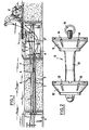
- FIG 1 there are shown buried tubes 1, 2, 3 for receiving cables, for example telephone. These tubes 1, 2, 3 extend between manholes 4, 5, into which it is possible to penetrate.
- the capsule 6 and the device 9 are shown in more detail in Figures 2 and 3.
- the capsule 6 made of plastic has two parts 10, 11, of frustoconical shape whose flare is directed towards the rear, these two parts being connected together by an axial sleeve 12.
- These frustoconical parts 10, 11 are provided with radial slots 13,14 which give these parts a certain elasticity which is favorable for obtaining a good seal with the inner surface of the tube 1.
- the rear of the capsule 6 has a ring 15 to which the rope 7 is intended to be fixed.
- the apparatus 9 shown in detail in FIG. 3 comprises a body 16 having a longitudinal duct 17 which opens to the outside through a nozzle 18 intended to be connected in a substantially sealed manner to the end of the tube 1.
- duct 17 opens a chamber 19 which communicates by means of an inlet duct 20 and a flexible pipe with the compressed air compressor.
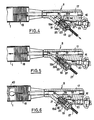
- This chamber 19 In the chamber 19 is slidably mounted, between two stops 21, 22, a body 23 for distributing the compressed air.
- This chamber 19 has two lateral intake openings 24, 25 which communicate via an annular chamber 26 with the intake duct 20.
- the end 21 of the chamber 19 opposite the connection end piece 18 communicates with a tube 27 (see FIGS. 4 to 6) provided with means for blocking the passage of compressed air which will be detailed below.
- two lateral exhaust openings, 28, 29 which open to the outside by an annular compartment 30 and an orifice 31.
- a ring 32 which can slide at the same time as the distribution body 23 towards a position in which this ring and this body 23 define between them a free passage 23 of the compressed air towards the connection end piece 18 and in which the ring 32 closes the side openings 28, 29 of exhaust as indicated in FIG. 3.
- the ring 32 can slide towards a position situated upstream from the previous one in which this ring releases the lateral exhaust openings 28, 29, as indicated in FIG. 6.
- the tubing 27 which communicates with the end 21 of the chamber 19 is a flexible tubing which can be pinched by the user to block the passage of the compressed air, as indicated in FIGS. 5 and 6.
- the distribution body 23 has its downstream end 34 shaped to form the seal with the downstream part 32a of the ring 32, when the distribution body 23 is abutted against the end 21 of the chamber 19 adjacent to the tubing 27.
- the lateral face of the distribution body 23 is hollowed out to define between this body 23 and the ring 32 the free passage 33 of the compressed air.
- the rear part of the distribution body 23 comprises a piston 35 constituting a stop which can bear against a shoulder 22 of the lateral face of the chamber 19, located slightly upstream of the lateral openings 24, 25 for admitting the compressed air into this chamber 19.
- This piston 35 has an orifice 37 which communicates with the lateral recesses of the body 23.
- the ring 32 has at its downstream end, an enlarged portion 35a, of frustoconical shape, which can bear against a complementary shoulder 36 formed on the lateral face of the chamber 19 upstream of the lateral openings 28, 29, of exhaust.
- the outlet piece 18 of the device 9 comprises (see FIGS. 3 to 7) a cylindrical sleeve 38, made of elastic material, with an outside diameter slightly greater than the inside diameter of the tube 1, and which can be pressed in force and substantially watertight in the end of this tube 1.
- the endpiece 18 has a lateral slot 39, extending parallel to the axis of this endpiece to guide the rope 7.
- This lateral slot 39 has a circular section opening to the outside by a narrowing which allows the introduction of the rope 7.
- the ring 32 bears by its enlarged part 35a against the shoulder 36 of the chamber 19 and the end 34 of the body 23 closes the downstream end 32a of the ring 32.
- the compressed air coming from the compressor enters the chamber 19 passing through the intake openings 24, 25 then escapes from this chamber through the orifice 37 of the piston 35 and through the flexible tubing 27.
- the capsule 6 is then propelled in the tube 1 towards the other end of it. It then suffices to attach the rope 7 attached to the capsule 6, to the cable, then to pull on the rope 7 to introduce the cable into the tube 1.
- the ring 32 is, thanks to this overpressure, immediately pushed backwards, as indicated in FIG. 6. During this movement, the ring 32 releases the exhaust openings 28, 29 , while the body 23 remains stationary. Thanks to these exhaust openings 28, 29, the pressure inside the tube 1, downstream of the device 9, is maintained at a value, for example less than or equal to 1.5 bar and the device 9 is not likely to be ejected.
- the device according to the invention therefore guarantees total security to users.
- the obturation of the flexible tubing 27 could be ensured by other gripping means of this tube, such as a valve controlled by mechanical, electrical or pneumatic means.
Landscapes
- Electric Cable Installation (AREA)
- Laying Of Electric Cables Or Lines Outside (AREA)
- Light Guides In General And Applications Therefor (AREA)
- Quick-Acting Or Multi-Walled Pipe Joints (AREA)
- Processing Of Terminals (AREA)
- Packages (AREA)
Claims (11)
Priority Applications (1)
| Application Number | Priority Date | Filing Date | Title |
|---|---|---|---|
| AT87401200T ATE58449T1 (de) | 1986-05-30 | 1987-05-27 | Pneumatische vorrichtung zum verlegen von kabeln in einem rohr. |
Applications Claiming Priority (2)
| Application Number | Priority Date | Filing Date | Title |
|---|---|---|---|
| FR8607820 | 1986-05-30 | ||
| FR8607820A FR2599566B1 (fr) | 1986-05-30 | 1986-05-30 | Dispositif pneumatique pour la mise en place de cables dans un tube. |
Publications (2)
| Publication Number | Publication Date |
|---|---|
| EP0247944A1 EP0247944A1 (de) | 1987-12-02 |
| EP0247944B1 true EP0247944B1 (de) | 1990-11-14 |
Family
ID=9335845
Family Applications (1)
| Application Number | Title | Priority Date | Filing Date |
|---|---|---|---|
| EP87401200A Expired - Lifetime EP0247944B1 (de) | 1986-05-30 | 1987-05-27 | Pneumatische Vorrichtung zum Verlegen von Kabeln in einem Rohr |
Country Status (11)
| Country | Link |
|---|---|
| US (1) | US4783054A (de) |
| EP (1) | EP0247944B1 (de) |
| AT (1) | ATE58449T1 (de) |
| DE (2) | DE247944T1 (de) |
| EG (1) | EG18300A (de) |
| ES (1) | ES2000412B3 (de) |
| FR (1) | FR2599566B1 (de) |
| GR (2) | GR880300015T1 (de) |
| MA (1) | MA20989A1 (de) |
| OA (1) | OA08603A (de) |
| TN (1) | TNSN87074A1 (de) |
Families Citing this family (22)
| Publication number | Priority date | Publication date | Assignee | Title |
|---|---|---|---|---|
| FR2623665B1 (fr) * | 1987-11-20 | 1996-10-31 | Baldechi Sauro | Procede a depression pneumatique permettant le tirage des cables dans les gaines et dispositif de mise en oeuvre |
| US5412858A (en) * | 1988-01-19 | 1995-05-09 | Brown; Colin | Method of encasing bundles of tubes |
| DE3911095A1 (de) * | 1989-04-06 | 1990-10-11 | Lancier Masch Peter | Verfahren zum einschiessen von kabeln o. ae. in schutzrohre mittels pressluft und gleichzeitiger schubunterstuetzung mittels schubmaschine |
| US5263686A (en) * | 1989-08-07 | 1993-11-23 | Sumitomo Electric Industries, Ltd. | Method and apparatus for laying and collecting a wire |
| JPH0774849B2 (ja) * | 1989-08-07 | 1995-08-09 | 住友電気工業株式会社 | 線材の布設・回収装置および布設・回収方法 |
| FR2670336A1 (fr) * | 1990-12-07 | 1992-06-12 | Morel Atel Electromec | Dispositif et procede pour installer un cable dans une canalisation. |
| EP0696096B1 (de) * | 1994-02-04 | 1998-09-09 | Kenichi Konno | Verlege- oder transportvorrichtung |
| US5813658A (en) * | 1994-11-23 | 1998-09-29 | Arnco Corporation | Cable feeding apparatus |
| US6012621A (en) | 1997-09-04 | 2000-01-11 | Condux International, Inc. | Cable conveying apparatus |
| GB9908480D0 (en) * | 1999-04-15 | 1999-06-09 | Sensor Highway Ltd | Pipeline cable deployment apparatus and method |
| IT1315026B1 (it) * | 2000-08-10 | 2003-01-27 | Bisazza Spa | Dispositivo per la produzione di pannelli di mosaico, relativoprocedimento e pannelli di mosaico cosi' ottenuti. |
| US7225533B2 (en) * | 2001-11-02 | 2007-06-05 | Neptco Incorporated | Apparatus for feeding elongated member into conduit |
| US7100274B2 (en) * | 2001-11-02 | 2006-09-05 | Neptco Incorporated | Apparatus for applying media to a conduit |
| CA2490996C (fr) * | 2002-07-01 | 2014-03-18 | Plumettaz Sa | Furet d'installation d'un cable dans un conduit |
| GB0326868D0 (en) * | 2003-11-18 | 2003-12-24 | Wood Group Logging Services In | Fiber optic deployment apparatus and method |
| WO2008011737A1 (fr) * | 2006-07-24 | 2008-01-31 | Plumettaz Sa | Dispositf d'installation d'un cable dans un conduit |
| US8387954B2 (en) * | 2007-08-30 | 2013-03-05 | Wesco Distribution, Inc. | System for the simultaneous introduction of two items into a conduit |
| US8459611B2 (en) * | 2007-08-30 | 2013-06-11 | Wesco Distribution, Inc. | System for the simultaneous introduction of two items into a conduit |
| US8413964B2 (en) * | 2007-12-28 | 2013-04-09 | Verizon Patent And Licensing Inc. | Fiber drop installation device |
| US8870162B2 (en) * | 2010-03-18 | 2014-10-28 | Wesco Distribution, Inc. | Method and apparatus for introducing an item into a conduit |
| ITMI20121813A1 (it) * | 2012-10-25 | 2014-04-26 | Sb Lab Sa | Dispositivo di chiusura di un condotto e kit per la posa di un filo guida in condotti di elevata lunghezza |
| EP3449540A4 (de) | 2016-04-28 | 2019-07-24 | CommScope, Inc. of North Carolina | Kabelblasvorrichtung und -verfahren |
Family Cites Families (6)
| Publication number | Priority date | Publication date | Assignee | Title |
|---|---|---|---|---|
| US3179375A (en) * | 1962-03-12 | 1965-04-20 | Jet Line Products Inc | Apparatus for laying lines in conduits |
| US3301531A (en) * | 1965-04-29 | 1967-01-31 | Richard J Corsiglia | Apparatus for installing electrical wire in electrical conduit |
| FR2191314B1 (de) * | 1972-07-05 | 1976-10-29 | Morel Ets Atel Lectrome | |
| SU535642A1 (ru) * | 1972-11-27 | 1976-11-15 | Пневматическое устройство дл зат гивани кабельных изделий в трубопроводы | |
| US4018421A (en) * | 1975-01-10 | 1977-04-19 | Erven Tallman | Portable lifting jack |
| US4498659A (en) * | 1982-03-02 | 1985-02-12 | Brockelsby Iii Pete | Conical line-pulling carrier |
-
1986
- 1986-05-30 FR FR8607820A patent/FR2599566B1/fr not_active Expired
-
1987
- 1987-05-27 EP EP87401200A patent/EP0247944B1/de not_active Expired - Lifetime
- 1987-05-27 TN TNTNSN87074A patent/TNSN87074A1/fr unknown
- 1987-05-27 AT AT87401200T patent/ATE58449T1/de not_active IP Right Cessation
- 1987-05-27 DE DE198787401200T patent/DE247944T1/de active Pending
- 1987-05-27 DE DE8787401200T patent/DE3766158D1/de not_active Expired - Lifetime
- 1987-05-27 OA OA59127A patent/OA08603A/xx unknown
- 1987-05-27 ES ES87401200T patent/ES2000412B3/es not_active Expired - Lifetime
- 1987-05-27 EG EG318/87A patent/EG18300A/xx active
- 1987-05-28 MA MA21228A patent/MA20989A1/fr unknown
- 1987-06-01 US US07/056,064 patent/US4783054A/en not_active Expired - Fee Related
-
1988
- 1988-05-20 GR GR88300015T patent/GR880300015T1/el unknown
-
1991
- 1991-02-07 GR GR91400156T patent/GR3001453T3/el unknown
Also Published As
| Publication number | Publication date |
|---|---|
| US4783054A (en) | 1988-11-08 |
| EP0247944A1 (de) | 1987-12-02 |
| TNSN87074A1 (fr) | 1990-01-01 |
| DE3766158D1 (de) | 1990-12-20 |
| GR880300015T1 (en) | 1988-10-18 |
| OA08603A (fr) | 1988-11-30 |
| DE247944T1 (de) | 1988-04-28 |
| ES2000412A4 (es) | 1988-03-01 |
| ATE58449T1 (de) | 1990-11-15 |
| MA20989A1 (fr) | 1987-12-31 |
| EG18300A (en) | 1992-10-30 |
| FR2599566B1 (fr) | 1988-09-02 |
| ES2000412B3 (es) | 1991-06-01 |
| FR2599566A1 (fr) | 1987-12-04 |
| GR3001453T3 (en) | 1992-10-08 |
Similar Documents
| Publication | Publication Date | Title |
|---|---|---|
| EP0247944B1 (de) | Pneumatische Vorrichtung zum Verlegen von Kabeln in einem Rohr | |
| CH629661A5 (fr) | Piece a main dentaire munie d'un dispositif de reglage des liquides d'arrosage de l'outil. | |
| CA2290804A1 (fr) | Raccord rapide de securite pour la jonction amovible de canalisations | |
| CA2599060C (fr) | Raccord rapide pour la jonction de deux canalisations d'acheminement d'un gaz sous pression | |
| EP0540800A1 (de) | Handstück mit Düse zur Körperpflege | |
| EP1106212B1 (de) | Feuerlöschdüse | |
| EP2548619A2 (de) | Tragbare Vorrichtung zum schnellen Aufblasen einer Tasche | |
| EP0883731B1 (de) | Kernbohrwerkzeug | |
| FR2781032A1 (fr) | Dispositif de regulation du debit d'eau avec moyen de decharge de pression | |
| WO1997025253A1 (fr) | Embout de distribution de produits liquides ou pateux | |
| WO2007134440A1 (fr) | Dispositif pneumatique autonome pour actionner un outil opéré par déplacement d'un organe d'actionnement | |
| FR2523002A1 (fr) | Outil a riveter | |
| EP1920133B1 (de) | Sicherheitsvorrichtung für ein ölbohrloch und entsprechende sicherheitsanlage | |
| FR2520479A1 (fr) | Raccord rapide auto-obturateur double recul avec verrouillage | |
| EP0961894B1 (de) | Monostabiles ventil | |
| FR2722416A1 (fr) | Extincteur | |
| EP0052567A1 (de) | Verfahren und Vorrichtung zum Entfernen des Dichtungsmaterials einer Dichtungsbüchse | |
| FR2602568A1 (fr) | Dispositif de guidage et de protection pour la pose de canalisations | |
| FR2496520A1 (fr) | Perfectionnements apportes aux chalumeaux oxy-acetyleniques | |
| CH354893A (fr) | Pièce à main pour fraise dentaire | |
| FR2776305A1 (fr) | Porte-lance comportant une tete de serrage multifonctions | |
| CA2176394C (fr) | Procede de commande d'un dispositif de distribution pour l'alimentation d'une capacite avec un fluide gazeux, moyens pour la mise en oeuvre de ce procede et dispositif equipe de ces moyens | |
| FR2582749A1 (fr) | Raccord-demarreur pour la mise en pression progressive des installations pneumatiques | |
| FR2703133A1 (fr) | Dispositif de coupure d'alimentation en gaz naturel, d'une canalisation en dépassement de débit normal d'utilisation. | |
| FR2940916A1 (fr) | Dispositif de projection d'un liquide pour aider a evaluer la temperature interne d'un local |
Legal Events
| Date | Code | Title | Description |
|---|---|---|---|
| PUAI | Public reference made under article 153(3) epc to a published international application that has entered the european phase |
Free format text: ORIGINAL CODE: 0009012 |
|
| 17P | Request for examination filed |
Effective date: 19870601 |
|
| AK | Designated contracting states |
Kind code of ref document: A1 Designated state(s): AT BE CH DE ES GB GR IT LI LU NL SE |
|
| ITCL | It: translation for ep claims filed |
Representative=s name: JACOBACCI CASETTA & PERANI S.P.A. |
|
| GBC | Gb: translation of claims filed (gb section 78(7)/1977) | ||
| TCAT | At: translation of patent claims filed | ||
| TCNL | Nl: translation of patent claims filed | ||
| DET | De: translation of patent claims | ||
| 17Q | First examination report despatched |
Effective date: 19900202 |
|
| GRAA | (expected) grant |
Free format text: ORIGINAL CODE: 0009210 |
|
| AK | Designated contracting states |
Kind code of ref document: B1 Designated state(s): AT BE CH DE ES GB GR IT LI LU NL SE |
|
| REF | Corresponds to: |
Ref document number: 58449 Country of ref document: AT Date of ref document: 19901115 Kind code of ref document: T |
|
| ITF | It: translation for a ep patent filed | ||
| REF | Corresponds to: |
Ref document number: 3766158 Country of ref document: DE Date of ref document: 19901220 |
|
| GBT | Gb: translation of ep patent filed (gb section 77(6)(a)/1977) | ||
| PLBE | No opposition filed within time limit |
Free format text: ORIGINAL CODE: 0009261 |
|
| STAA | Information on the status of an ep patent application or granted ep patent |
Free format text: STATUS: NO OPPOSITION FILED WITHIN TIME LIMIT |
|
| 26N | No opposition filed | ||
| ITTA | It: last paid annual fee | ||
| REG | Reference to a national code |
Ref country code: GR Ref legal event code: FG4A Free format text: 3001453 |
|
| EPTA | Lu: last paid annual fee | ||
| EAL | Se: european patent in force in sweden |
Ref document number: 87401200.8 |
|
| PGFP | Annual fee paid to national office [announced via postgrant information from national office to epo] |
Ref country code: LU Payment date: 19950501 Year of fee payment: 9 |
|
| PGFP | Annual fee paid to national office [announced via postgrant information from national office to epo] |
Ref country code: AT Payment date: 19950512 Year of fee payment: 9 |
|
| PGFP | Annual fee paid to national office [announced via postgrant information from national office to epo] |
Ref country code: SE Payment date: 19950517 Year of fee payment: 9 |
|
| PGFP | Annual fee paid to national office [announced via postgrant information from national office to epo] |
Ref country code: CH Payment date: 19950524 Year of fee payment: 9 |
|
| PGFP | Annual fee paid to national office [announced via postgrant information from national office to epo] |
Ref country code: GR Payment date: 19950530 Year of fee payment: 9 |
|
| PGFP | Annual fee paid to national office [announced via postgrant information from national office to epo] |
Ref country code: NL Payment date: 19950531 Year of fee payment: 9 |
|
| PGFP | Annual fee paid to national office [announced via postgrant information from national office to epo] |
Ref country code: BE Payment date: 19950706 Year of fee payment: 9 |
|
| PGFP | Annual fee paid to national office [announced via postgrant information from national office to epo] |
Ref country code: ES Payment date: 19960509 Year of fee payment: 10 |
|
| PGFP | Annual fee paid to national office [announced via postgrant information from national office to epo] |
Ref country code: GB Payment date: 19960520 Year of fee payment: 10 |
|
| PG25 | Lapsed in a contracting state [announced via postgrant information from national office to epo] |
Ref country code: LU Free format text: LAPSE BECAUSE OF NON-PAYMENT OF DUE FEES Effective date: 19960527 Ref country code: AT Effective date: 19960527 |
|
| PG25 | Lapsed in a contracting state [announced via postgrant information from national office to epo] |
Ref country code: SE Effective date: 19960528 |
|
| PG25 | Lapsed in a contracting state [announced via postgrant information from national office to epo] |
Ref country code: LI Effective date: 19960531 Ref country code: CH Effective date: 19960531 Ref country code: BE Effective date: 19960531 |
|
| PGFP | Annual fee paid to national office [announced via postgrant information from national office to epo] |
Ref country code: DE Payment date: 19960731 Year of fee payment: 10 |
|
| BERE | Be: lapsed |
Owner name: ETS MOREL - ATELIERS ELECTROMECANIQUES DE FAVIERE Effective date: 19960531 |
|
| PG25 | Lapsed in a contracting state [announced via postgrant information from national office to epo] |
Ref country code: GR Free format text: THE PATENT HAS BEEN ANNULLED BY A DECISION OF A NATIONAL AUTHORITY Effective date: 19961130 |
|
| PG25 | Lapsed in a contracting state [announced via postgrant information from national office to epo] |
Ref country code: NL Effective date: 19961201 |
|
| REG | Reference to a national code |
Ref country code: GR Ref legal event code: MM2A Free format text: 3001453 |
|
| REG | Reference to a national code |
Ref country code: CH Ref legal event code: PL |
|
| EUG | Se: european patent has lapsed |
Ref document number: 87401200.8 |
|
| NLV4 | Nl: lapsed or anulled due to non-payment of the annual fee |
Effective date: 19961201 |
|
| PG25 | Lapsed in a contracting state [announced via postgrant information from national office to epo] |
Ref country code: GB Effective date: 19970527 |
|
| PG25 | Lapsed in a contracting state [announced via postgrant information from national office to epo] |
Ref country code: ES Free format text: LAPSE BECAUSE OF NON-PAYMENT OF DUE FEES Effective date: 19970528 |
|
| GBPC | Gb: european patent ceased through non-payment of renewal fee |
Effective date: 19970527 |
|
| PG25 | Lapsed in a contracting state [announced via postgrant information from national office to epo] |
Ref country code: DE Free format text: LAPSE BECAUSE OF NON-PAYMENT OF DUE FEES Effective date: 19980203 |
|
| REG | Reference to a national code |
Ref country code: ES Ref legal event code: FD2A Effective date: 19990301 |
|
| PG25 | Lapsed in a contracting state [announced via postgrant information from national office to epo] |
Ref country code: IT Free format text: LAPSE BECAUSE OF NON-PAYMENT OF DUE FEES;WARNING: LAPSES OF ITALIAN PATENTS WITH EFFECTIVE DATE BEFORE 2007 MAY HAVE OCCURRED AT ANY TIME BEFORE 2007. THE CORRECT EFFECTIVE DATE MAY BE DIFFERENT FROM THE ONE RECORDED. Effective date: 20050527 |