EP0247830B1 - Halbtonreproduktion - Google Patents
Halbtonreproduktion Download PDFInfo
- Publication number
- EP0247830B1 EP0247830B1 EP87304650A EP87304650A EP0247830B1 EP 0247830 B1 EP0247830 B1 EP 0247830B1 EP 87304650 A EP87304650 A EP 87304650A EP 87304650 A EP87304650 A EP 87304650A EP 0247830 B1 EP0247830 B1 EP 0247830B1
- Authority
- EP
- European Patent Office
- Prior art keywords
- dot
- scan lines
- exposing
- tone
- digital data
- Prior art date
- Legal status (The legal status is an assumption and is not a legal conclusion. Google has not performed a legal analysis and makes no representation as to the accuracy of the status listed.)
- Expired
Links
Images


Classifications
-
- H—ELECTRICITY
- H04—ELECTRIC COMMUNICATION TECHNIQUE
- H04N—PICTORIAL COMMUNICATION, e.g. TELEVISION
- H04N1/00—Scanning, transmission or reproduction of documents or the like, e.g. facsimile transmission; Details thereof
- H04N1/40—Picture signal circuits
- H04N1/40081—Soft dot halftoning, i.e. producing halftone dots with gradual edges
-
- H—ELECTRICITY
- H04—ELECTRIC COMMUNICATION TECHNIQUE
- H04N—PICTORIAL COMMUNICATION, e.g. TELEVISION
- H04N1/00—Scanning, transmission or reproduction of documents or the like, e.g. facsimile transmission; Details thereof
- H04N1/04—Scanning arrangements, i.e. arrangements for the displacement of active reading or reproducing elements relative to the original or reproducing medium, or vice versa
- H04N1/06—Scanning arrangements, i.e. arrangements for the displacement of active reading or reproducing elements relative to the original or reproducing medium, or vice versa using cylindrical picture-bearing surfaces, i.e. scanning a main-scanning line substantially perpendicular to the axis and lying in a curved cylindrical surface
- H04N1/0657—Scanning a transparent surface, e.g. reading a transparency original
-
- H—ELECTRICITY
- H04—ELECTRIC COMMUNICATION TECHNIQUE
- H04N—PICTORIAL COMMUNICATION, e.g. TELEVISION
- H04N1/00—Scanning, transmission or reproduction of documents or the like, e.g. facsimile transmission; Details thereof
- H04N1/04—Scanning arrangements, i.e. arrangements for the displacement of active reading or reproducing elements relative to the original or reproducing medium, or vice versa
- H04N1/06—Scanning arrangements, i.e. arrangements for the displacement of active reading or reproducing elements relative to the original or reproducing medium, or vice versa using cylindrical picture-bearing surfaces, i.e. scanning a main-scanning line substantially perpendicular to the axis and lying in a curved cylindrical surface
- H04N1/0671—Scanning arrangements, i.e. arrangements for the displacement of active reading or reproducing elements relative to the original or reproducing medium, or vice versa using cylindrical picture-bearing surfaces, i.e. scanning a main-scanning line substantially perpendicular to the axis and lying in a curved cylindrical surface with sub-scanning by translational movement of the main-scanning components
- H04N1/0678—Scanning arrangements, i.e. arrangements for the displacement of active reading or reproducing elements relative to the original or reproducing medium, or vice versa using cylindrical picture-bearing surfaces, i.e. scanning a main-scanning line substantially perpendicular to the axis and lying in a curved cylindrical surface with sub-scanning by translational movement of the main-scanning components using a lead-screw or worm
-
- H—ELECTRICITY
- H04—ELECTRIC COMMUNICATION TECHNIQUE
- H04N—PICTORIAL COMMUNICATION, e.g. TELEVISION
- H04N1/00—Scanning, transmission or reproduction of documents or the like, e.g. facsimile transmission; Details thereof
- H04N1/04—Scanning arrangements, i.e. arrangements for the displacement of active reading or reproducing elements relative to the original or reproducing medium, or vice versa
- H04N1/06—Scanning arrangements, i.e. arrangements for the displacement of active reading or reproducing elements relative to the original or reproducing medium, or vice versa using cylindrical picture-bearing surfaces, i.e. scanning a main-scanning line substantially perpendicular to the axis and lying in a curved cylindrical surface
-
- H—ELECTRICITY
- H04—ELECTRIC COMMUNICATION TECHNIQUE
- H04N—PICTORIAL COMMUNICATION, e.g. TELEVISION
- H04N2201/00—Indexing scheme relating to scanning, transmission or reproduction of documents or the like, and to details thereof
- H04N2201/04—Scanning arrangements
- H04N2201/0402—Arrangements not specific to a particular one of the scanning methods covered by groups H04N1/04 - H04N1/207
- H04N2201/0458—Additional arrangements for improving or optimising scanning resolution or quality
Definitions
- the invention relates to methods for generating a half-tone representation of an image.
- Conventional electronic scanners such as our Crosfield Magnascan 645, scan an original image in a series of substantially parallel and abutting input scan lines, the resultant signals being regularly sampled, each sample corresponding to an individual pixel.
- the colour content of each pixel is determined and defined in terms of digital data which is then optionally modified and stored or fed directly to an output scanner.
- the output scanner generates an exposing beam which scans a record medium in a series of substantially parallel and abutting output scan lines.
- the exposing beam is modulated under the control of the digital data and half-tone information so that a series of half-tone dots are recorded on the record medium, the size of the dots corresponding to the colour content of the corresponding pixels in the original image used to define the area corresponding to the dot.
- one half-tone dot will correspond to four pixels in the original image.
- the half-tone representation will comprise two or more, usually four, colour separations corresponding to the printing inks cyan, magenta, yellow and black.
- a method of generating a half-tone representation of an image from digital data defining the colour content of pixels arranged in a series of substantially parallel, overlapping input scan lines comprises exposing at least one record medium to an exposing beam in a series of substantially parallel, overlapping output scan lines, each corresponding to a respective input scan line, the exposing beam being modulated under the control of the digital data and half-tone information, and the intensity of the exposing beam and the nature of the record medium being such that an area of the record medium will only record a half-tone dot or a portion of a half-tone dot after all output scan lines passing through that area have been exposed.
- the invention improves the reproduction of the edges of image features and the like by defining the image in terms of pixels arranged in a series of overlapping scan lines. This increases the graphics line rate but maintains the screen grid unchanged so that the resultant representation is satisfactory for use with conventional printing equipment. Furthermore, no modifications are required to the optical components of conventional scanning apparatus used to carry out the method.
- a further significant advantage of the invention is that by providing overlapping output scan lines, any differences between the apparent colour content of pixels due to noise and the like is averaged out on the record medium thus removing the need for complex electronics to produce this averaging.
- a typical output scan line will overlap only the preceding and succeeding scan lines.
- a higher degree of overlap is also feasible but will result in longer exposure times.
- the intensity of the exposing radiation beam will be reduced by about 40% or more from that used in conventional systems without overlapping scan lines.
- the degree of reduction is determined empirically and depends primarily on the number of times a scan line is overlapped and on the response of the record medium.
- Typical record media exhibit a threshold such that when they are exposed to a beam having an energy above the threshold they will exhibit a significant density change whereas when they are exposed to a beam having an energy below the threshold, only a very small change in density will occur.
- the exposing beam comprises a number, conveniently six, of subsidiary beams which may be modulated together or separately in response to the digital data and half-tone information.
- the record medium may comprise a radiation sensitive sheet or the like or for example a gravure cylinder which is etched by the exposing beam.
- the digital data may have been generated electronically but preferably is generated by scanning an original image in a series of substantially parallel, overlapping input scan lines, each scan line being defined by a plurality of pixels; determining the colour content of each pixel; and representing the determined colour content, possibly after modification, in a digital form.
- Conventional apparatus for producing half-tone colour separations from an original image generally comprises at least two rotating coaxial drums as shown in Figure 1.
- An original 22 is wrapped round one drum 10 and record media defining output surfaces 28, 30, 32, 34 which are to be exposed are wrapped round another drum 11 or drums, the drums being in this case driven by a common motor 35.
- the output surfaces for the different colour separations may occupy successive sections (eg.28, 30) of the perimeter of one output drum, they may be relatively displaced (as at 30, 32) along the axis of the drum, or they may be arranged on different drums.
- the original image is scanned by an opto-electronic scanning head 24 by rotating its drum 10 past the head 24 and imparting in addition a slow longitudinal movement to the head so that the scanning path on the surface of the cylindrical drum is helical.
- Signals from the scanning head then pass through a colour corrector (signal processing unit) 1, if necessary, in which a fourth signal, black is also usually generated, and emerge as the "picture signals" yellow (Y), magenta (M), cyan (C), black (B) for that particular colour.
- the output surfaces which are sensitive to light from an exposing head 26 adjacent to the other drums, are scanned by the exposing head in a similar manner, and are exposed progressively to a set of six laser beams to generate a half-tone pattern made from dots of a size depending on the colour tonal density of the original.
- the cylinders 10, 11 are separately driven and are not coaxial while a single expose head is provided with the colour separations 28, 30, 32, 34 spaced circumferentially around the cylinder 11.
- Movement of the scanning and exposing heads 24, 26 is achieved by rotating respective lead screws 50, 52 on which the heads are mounted.
- Each lead screw 50, 52 is rotated by a respective motor 54, 56 controlled by a computer 3.
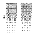
- the computer 3 also monitor the rotational positions of the drums 10, 11 via conventional timing discs 58 and optical detectors 60. Examples of half-tone patterns are shown in Figure 2, in which the tonal density increases from left to right.
- the signals 4, 5 controlling the modulation of light from a source 27 are obtained from a screen computer 2 fed with the colour component signals Y, M, C and B.
- the dots shown in Figure 3 by way of example are square dots “tilted” at 45° to the grid, the shaded areas being bounded by the dot borders (DB).
- the patterns of dots shown may be created on the output surface by controlling the scanning beam by an "on/off" signal in accordance with whether the scanning beam lies over a dot ("on") or a space ("off") in the overlying screen grid. At each point marked x, the value of this signal is indicated by "1" or "0". The signal is obtained subsequently for all similar points along the helical path SB of the scan which overlie the output surface.
- one dot area is shown in dotted lines.
- the diagram has been rotated through the screen angle ⁇ relative to the diagram of Figure 3.
- a dot bounded by the border DB2 is 50% the maximum dot size.
- a small dot might have a border DB1, but from now on an intermediate dot size will be assumed, the dot having a border DB. It is useful to equate the value of the picture signal (PS) with half the dot width: in this way the picture signal is seen to determine the dot size directly.
- PS picture signal
- the position x of the "write" scanning beam relative to a dot area (DA) and a dot border (DB) is described by two position signals. These may be relative to coordinate axes (X, Y) aligned with the dot area boundaries as shown, or axes at 45° to the dot area boundaries for example.
- X, Y coordinate axes
- X and Y coordinate axes
- ⁇ X and ⁇ Y are determined by the screen angle ⁇ and by the desired line spacing.
- the degree of magnification of the final screen grid can be controlled by the size of the increment.
- ⁇ X and ⁇ Y are added many times during the traversal of one dot area.
- the values of the increments determine the screen angle, and may be changed at the beginning of each new vertical scanning lines, ie. at the edge of the separation.
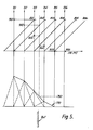
- the intensity profile provided by six, simultaneously generated parallel beams, over the edge of a "soft" dot, is illustrated schematically in Figure 5.
- the individual intensity profile of each beam can be represented and treated as triangular in shape, rising to a sharp peak at the centre. This is an approximation to the Gaussian variation of intensity produced in practice by a laser optical system, as is known in the art.
- the beams are arranged across the output surface with an equal spacing in the horizontal direction, so that their intensity profiles overlap, as shown in Figure 7.
- all the beams are modulated to the same level of intensity, but in practice they will be different, as shown in Figure 5, in regions where the required density is varying, such as over a dot border.
- the index signal I for a given scanning beam may be, for example, the difference between the picture signal PS and a position signal PV, shown as PS-PV in Figure 6 in which the horizontal axis represents PS-PV in volts.
- the intensity of the scanning beam is below the film threshold value; in regions inside the dot border, it is above the threshold value.
- darkest regions eg.
- the level preferably exceeds 200% of the film threshold value, and may even reach 300%.
- the variation of the beam intensity is preferably a linear function of the distance of the beam from the dot border, varying between a zero value and a maximum value.
- the vertical axis represents beam intensity
- the horizontal axis PS-PV as in Figure 6.
- the dot border 760 is shown at the bottom of the Figure.
- a first scanning beam 701 is controlled by a first position computer and dot border computer. When it is at the relative position on the screen grid shown in the Figure, the intensity function 801 requires that for such a large negative value of PS-PV the intensity should be at the maximum value, 901. The resulting contribution made by beam 701 to the overall intensity 770 is shown in dotted lines.
- a second beam 702 gives an intermediate level of intensity 902, as determined by the intersection of curve 802 with the vertical axis.
- the remaining four beams, 703 to 706, provide levels of intensity 903 to 906 in accordance with the curves 804 to 806, respectively.
- the slope of the intensity curve 770 defining the profile of the dot is arranged to be sufficiently steep at the point 750 that the film threshold level is exceeded, that the dot border is well defined and does not vary substantially with small regional variations in the film threshold value.
- the slope of the curve 750 should not be so steep that the dot so produced is not etchable, ie. does not change its size gradually with the application of a chemical etching agent on the resulting film.
- each input and output scan line abuts the preceding and succeeding lines.
- adjacent input and output scan lines overlap and Figure 8 illustrates an example in which each scan line overlaps the preceding and succeeding scan lines.
- two output scan lines 100, 101 are shown and it will be seen that one edge 110 of the scanline 101 is positioned in alignment with the centre of the scan line 100.
- each portion of the record medium will be traversed by two output scan lines.
- the output scan lines can be caused to overlap simply by slowing down the traverse speed of the exposing head 26 by suitably controlling the motor 56. It should be noted that the ⁇ X and ⁇ Y values at the start of each line would need to modified.
- the traverse speed of the scanning head 24 is slowed down so that the original 22 is scanned by a series of overlapping input scan lines similar to and having a one to one relationship with the output scan lines 100, 101.
- the input scan lines are analysed as in the conventional system to generate digital data defining the colour content of each pixel and this digital data is used by the computer 2 (clocked by the computer 3) to control the exposure of the record medium. It should be noted that the pixels overlap.
- Figure 8 also illustrates the intensity profile for the six subsidiary, exposing laser beams 102-107 and this should be compared with Figure 7.
- the maximum intensity of each subsidiary beam is about 40% of the maximum intensity that the subsidiary beam would have in the conventional system as illustrated by a dashed line 108.
- the profile 108 corresponds to the profile 108 shown in Figure 7.
- FIG. 9 The response of a conventional record medium to exposing radiation is shown in Figure 9 where it will be seen to exhibit a threshold 109 at a particular total exposure energy.
- the characteristic of suitable record mediums is such that the effect of exposing the same area of the record medium to more than one beam is equivalent to exposing the area to a single beam having an energy equivalent to the sum of the energies of the repeated beams.
- the total energy received by an area of the record medium where no dot portion is to be recorded is less than the threshold 109 but where a dot portion is to be created, the total incident energy is greater than the threshold 109.
Landscapes
- Engineering & Computer Science (AREA)
- Multimedia (AREA)
- Signal Processing (AREA)
- Laser Beam Printer (AREA)
- Exposure Or Original Feeding In Electrophotography (AREA)
- Facsimile Image Signal Circuits (AREA)
- Dot-Matrix Printers And Others (AREA)
- Color, Gradation (AREA)
- Facsimile Scanning Arrangements (AREA)
Claims (4)
Applications Claiming Priority (2)
| Application Number | Priority Date | Filing Date | Title |
|---|---|---|---|
| GB868613223A GB8613223D0 (en) | 1986-05-30 | 1986-05-30 | Half-tone reproduction |
| GB8613223 | 1986-05-30 |
Publications (2)
| Publication Number | Publication Date |
|---|---|
| EP0247830A1 EP0247830A1 (de) | 1987-12-02 |
| EP0247830B1 true EP0247830B1 (de) | 1991-01-09 |
Family
ID=10598714
Family Applications (1)
| Application Number | Title | Priority Date | Filing Date |
|---|---|---|---|
| EP87304650A Expired EP0247830B1 (de) | 1986-05-30 | 1987-05-26 | Halbtonreproduktion |
Country Status (5)
| Country | Link |
|---|---|
| US (1) | US4768101A (de) |
| EP (1) | EP0247830B1 (de) |
| JP (1) | JPS62291266A (de) |
| DE (1) | DE3767218D1 (de) |
| GB (1) | GB8613223D0 (de) |
Families Citing this family (14)
| Publication number | Priority date | Publication date | Assignee | Title |
|---|---|---|---|---|
| EP0286241B1 (de) * | 1987-03-11 | 1993-02-10 | YAMATOYA & CO., LTD. | Fotomechanischer Apparat unter Verwendung von fotoelektrischer Abtastung |
| CA1324803C (en) * | 1989-01-25 | 1993-11-30 | Wallace Edwards | Printing method and printed product |
| US5074206A (en) * | 1989-01-25 | 1991-12-24 | Wallace Edwards | Printing method and printed product |
| US5107331A (en) * | 1989-03-07 | 1992-04-21 | The Color Group | Method and apparatus for producing half-tone separations at the same screen angle |
| EP0465558A4 (en) * | 1989-03-07 | 1992-10-28 | The Color Group | Method and apparatus for producing half-tone separations in color imaging |
| US6163382A (en) | 1989-07-20 | 2000-12-19 | Netz; Yoel | Devices and methods for offset and similar printing systems |
| US5793500A (en) * | 1989-07-20 | 1998-08-11 | Netz; Yoel | Devices and methods for offset and similar printing systems |
| US5227895A (en) * | 1990-08-03 | 1993-07-13 | Scitex Corporation Ltd. | Method and apparatus for image reproduction |
| US5134495A (en) * | 1990-11-07 | 1992-07-28 | Dp-Tek, Inc. | Resolution transforming raster-based imaging system |
| US5446558A (en) * | 1992-10-05 | 1995-08-29 | Eastman Kodak Company | Apparatus and associated method for representing elliptical halftone dots |
| US5448366A (en) * | 1992-10-05 | 1995-09-05 | Eastman Kodak Company | Apparatus and method for noise distorting the painting of a halftone dot |
| JP2772504B2 (ja) * | 1993-03-26 | 1998-07-02 | 大日本スクリーン製造株式会社 | 網角度が変更可能な網目版画像生成装置 |
| IL106514A (en) * | 1993-07-28 | 1997-08-14 | Scitex Corp Ltd | Apparatus and method for screening images for reproduction |
| DE20121871U1 (de) * | 2001-07-25 | 2003-08-14 | Leonhard Kurz GmbH & Co. KG, 90763 Fürth | Durch Drucken erzeugtes Halbtonbild |
Family Cites Families (14)
| Publication number | Priority date | Publication date | Assignee | Title |
|---|---|---|---|---|
| US1688081A (en) * | 1925-03-02 | 1928-10-16 | Western Electric Co | Transmission of pictures by electricity |
| GB321389A (en) * | 1928-06-05 | 1929-11-05 | John Logie Baird | Improvements in or relating to television apparatus and the like |
| DE2348955C3 (de) * | 1972-11-24 | 1980-05-22 | Xerox Corp., Rochester, N.Y. (V.St.A.) | Verfahren zur Faksimile-Übertragung einer graphischen Vorlage |
| US3876829A (en) * | 1973-04-20 | 1975-04-08 | Massachusetts Inst Technology | Electro-optical communication of visual images |
| GB1492740A (en) * | 1973-12-17 | 1977-11-23 | Crosfield Electronics Ltd | Preparation of half-tone images |
| GB1523032A (en) * | 1976-03-03 | 1978-08-31 | Crosfield Electronics Ltd | Image reproducing apparatus |
| DE2635674C3 (de) * | 1976-08-07 | 1978-10-26 | Dr.-Ing. Rudolf Hell Gmbh, 2300 Kiel | Verfahren zur zeilenfreien Bildaufzeichnung |
| JPS55120507A (en) * | 1979-03-12 | 1980-09-17 | Lion Corp | Hair rinse composition |
| FR2463433A1 (fr) * | 1979-08-14 | 1981-02-20 | Cit Alcatel | Dispositif de reproduction d'une image a densite variable de teinte |
| US4419690A (en) * | 1980-09-01 | 1983-12-06 | Crosfield Electronics Limited | Method and apparatus for producing a half-tone reproduction |
| JPS5912671A (ja) * | 1982-07-12 | 1984-01-23 | Dainippon Screen Mfg Co Ltd | 画像走査記録方法 |
| GB8401933D0 (en) * | 1984-01-25 | 1984-02-29 | Crosfield Electronics Ltd | Half-tone imaging |
| GB8410861D0 (en) * | 1984-04-27 | 1984-06-06 | Crosfield Electronics Ltd | Half-tone dot imaging |
| JPS6113215A (ja) * | 1984-06-28 | 1986-01-21 | Fuji Photo Film Co Ltd | 半導体レ−ザ走査装置 |
-
1986
- 1986-05-30 GB GB868613223A patent/GB8613223D0/en active Pending
-
1987
- 1987-05-21 US US07/052,329 patent/US4768101A/en not_active Expired - Lifetime
- 1987-05-26 JP JP62127292A patent/JPS62291266A/ja active Pending
- 1987-05-26 DE DE8787304650T patent/DE3767218D1/de not_active Expired - Lifetime
- 1987-05-26 EP EP87304650A patent/EP0247830B1/de not_active Expired
Also Published As
| Publication number | Publication date |
|---|---|
| DE3767218D1 (de) | 1991-02-14 |
| EP0247830A1 (de) | 1987-12-02 |
| JPS62291266A (ja) | 1987-12-18 |
| US4768101A (en) | 1988-08-30 |
| GB8613223D0 (en) | 1986-07-02 |
Similar Documents
| Publication | Publication Date | Title |
|---|---|---|
| US4468706A (en) | Imaging by varying the placement of elements in the pixels | |
| EP0247830B1 (de) | Halbtonreproduktion | |
| US4051536A (en) | Electronic halftone imaging system | |
| US5396584A (en) | Multi-bit image edge enhancement method and apparatus | |
| EP0047145B1 (de) | Verfahren zum Erzeugen einer Halbtonreproduktion | |
| DE69026159T2 (de) | Bildverarbeitungsgerät | |
| US4543613A (en) | Method for producing halftone dots in a halftone plate recording apparatus | |
| DE69328660T2 (de) | Bildverarbeitungsvorrichtung | |
| US6606420B1 (en) | Method and apparatus for digital image darkness control in saturated image structures | |
| GB2149611A (en) | Enhancement halftoning | |
| DE2720782A1 (de) | Elektronischer halbton-generator | |
| EP0549314A1 (de) | Verbessertes Drucken von Bildern, durch hierarchischen Vergleich mit Standardmuster | |
| US6332044B1 (en) | System and method for enhancement of image contour fidelity | |
| EP1267564B1 (de) | Verfahren zur Bestimmung einer Schwellenmatrix zur Erzeugung eines Gradationsbildes | |
| EP0585043B1 (de) | Vorrichtung und System für verbessertes Drucken von Bildern | |
| US5140431A (en) | Digital electronic system for halftone printing | |
| US4390903A (en) | Imaging system and method with mid-tone enhancement | |
| EP0342845B1 (de) | Halbtonbilderzeugung | |
| US4566042A (en) | Electrophotographic imaging apparatus by variably placing pixel elements | |
| US5822086A (en) | Method and device for adaptive screening of continuous tone originals | |
| JPH05904B2 (de) | ||
| EP0893780B1 (de) | Verfahren zur Auflösungsumwandlung von Druckdaten für einen Drucker | |
| EP0235631A2 (de) | Verfahren zur Erzeugung eines Halbtonrasters | |
| JPH0785272A (ja) | 周波数変調ハーフトーン画像および作成方法 | |
| US5740330A (en) | Exposure controlling method and an exposure controlling apparatus |
Legal Events
| Date | Code | Title | Description |
|---|---|---|---|
| PUAI | Public reference made under article 153(3) epc to a published international application that has entered the european phase |
Free format text: ORIGINAL CODE: 0009012 |
|
| AK | Designated contracting states |
Kind code of ref document: A1 Designated state(s): DE GB |
|
| 17P | Request for examination filed |
Effective date: 19880512 |
|
| 17Q | First examination report despatched |
Effective date: 19900406 |
|
| GRAA | (expected) grant |
Free format text: ORIGINAL CODE: 0009210 |
|
| AK | Designated contracting states |
Kind code of ref document: B1 Designated state(s): DE GB |
|
| REF | Corresponds to: |
Ref document number: 3767218 Country of ref document: DE Date of ref document: 19910214 |
|
| PLBE | No opposition filed within time limit |
Free format text: ORIGINAL CODE: 0009261 |
|
| 26N | No opposition filed | ||
| REG | Reference to a national code |
Ref country code: GB Ref legal event code: 732E |
|
| REG | Reference to a national code |
Ref country code: GB Ref legal event code: IF02 |
|
| PGFP | Annual fee paid to national office [announced via postgrant information from national office to epo] |
Ref country code: GB Payment date: 20020522 Year of fee payment: 16 |
|
| PGFP | Annual fee paid to national office [announced via postgrant information from national office to epo] |
Ref country code: DE Payment date: 20020529 Year of fee payment: 16 |
|
| PG25 | Lapsed in a contracting state [announced via postgrant information from national office to epo] |
Ref country code: GB Free format text: LAPSE BECAUSE OF NON-PAYMENT OF DUE FEES Effective date: 20030526 |
|
| PG25 | Lapsed in a contracting state [announced via postgrant information from national office to epo] |
Ref country code: DE Free format text: LAPSE BECAUSE OF NON-PAYMENT OF DUE FEES Effective date: 20031202 |
|
| GBPC | Gb: european patent ceased through non-payment of renewal fee |
Effective date: 20030526 |