EP0247818A2 - Vorrichtung zur Verhinderung von Abstürzen - Google Patents
Vorrichtung zur Verhinderung von Abstürzen Download PDFInfo
- Publication number
- EP0247818A2 EP0247818A2 EP87304626A EP87304626A EP0247818A2 EP 0247818 A2 EP0247818 A2 EP 0247818A2 EP 87304626 A EP87304626 A EP 87304626A EP 87304626 A EP87304626 A EP 87304626A EP 0247818 A2 EP0247818 A2 EP 0247818A2
- Authority
- EP
- European Patent Office
- Prior art keywords
- fail
- brake
- drum
- threaded
- safe
- Prior art date
- Legal status (The legal status is an assumption and is not a legal conclusion. Google has not performed a legal analysis and makes no representation as to the accuracy of the status listed.)
- Withdrawn
Links
- 230000000750 progressive effect Effects 0.000 claims abstract description 5
- 230000008878 coupling Effects 0.000 claims description 5
- 238000010168 coupling process Methods 0.000 claims description 5
- 238000005859 coupling reaction Methods 0.000 claims description 5
- 230000007257 malfunction Effects 0.000 claims description 3
- 239000006096 absorbing agent Substances 0.000 claims description 2
- 230000000007 visual effect Effects 0.000 claims 1
- 230000007246 mechanism Effects 0.000 description 10
- 230000001133 acceleration Effects 0.000 description 6
- 239000010425 asbestos Substances 0.000 description 6
- 229910052895 riebeckite Inorganic materials 0.000 description 6
- 229910000639 Spring steel Inorganic materials 0.000 description 3
- 230000000712 assembly Effects 0.000 description 2
- 238000000429 assembly Methods 0.000 description 2
- 230000035939 shock Effects 0.000 description 2
- 239000010935 stainless steel Substances 0.000 description 2
- 229910001220 stainless steel Inorganic materials 0.000 description 2
- 229910000838 Al alloy Inorganic materials 0.000 description 1
- 229910001369 Brass Inorganic materials 0.000 description 1
- 241000700159 Rattus Species 0.000 description 1
- 229910000831 Steel Inorganic materials 0.000 description 1
- 230000009286 beneficial effect Effects 0.000 description 1
- 239000010951 brass Substances 0.000 description 1
- 230000006835 compression Effects 0.000 description 1
- 238000007906 compression Methods 0.000 description 1
- 238000010276 construction Methods 0.000 description 1
- 230000001419 dependent effect Effects 0.000 description 1
- 230000006866 deterioration Effects 0.000 description 1
- 238000006073 displacement reaction Methods 0.000 description 1
- 230000000694 effects Effects 0.000 description 1
- 230000007613 environmental effect Effects 0.000 description 1
- 230000001771 impaired effect Effects 0.000 description 1
- 238000003780 insertion Methods 0.000 description 1
- 230000037431 insertion Effects 0.000 description 1
- 238000007689 inspection Methods 0.000 description 1
- 239000000463 material Substances 0.000 description 1
- 230000002093 peripheral effect Effects 0.000 description 1
- 239000010959 steel Substances 0.000 description 1
- 238000005303 weighing Methods 0.000 description 1
- 238000004804 winding Methods 0.000 description 1
Images


Classifications
-
- A—HUMAN NECESSITIES
- A62—LIFE-SAVING; FIRE-FIGHTING
- A62B—DEVICES, APPARATUS OR METHODS FOR LIFE-SAVING
- A62B35/00—Safety belts or body harnesses; Similar equipment for limiting displacement of the human body, especially in case of sudden changes of motion
- A62B35/0093—Fall arrest reel devices
Definitions
- This invention relates to apparatus comprising a rotatably mounted drum or spool on which a rope, cable or other coilable tie member can be wound, and a braking mechanism which automatically stops or retards rotation of the drum or spool if its rotational speed or acceleration rises above a certain value.
- Apparatus of this kind can be used, for example, for safety lowering or fall-arrest purposes by attaching the drum or spool holder or casing to a fixture and attaching the free end of a safety line, wound onto the drum or spool, to a person or object to be protected.
- a particularly important use of such apparatus is for the protection of a person working at high levels above the ground, using a safety line which is attached to a personal safety belt or harness.
- Apparatus for such purpose customarily incorporates a drum which is self-winding by spring action so that slack in the safety line is automatically taken up and cannot accumulate and thereby create a further safety hazard.
- the automatic braking of the drum or spool if its unwinding speed exceeds a certain value can be achieved by means of a friction brake operated by a centrifugal clutch. Engagement of the clutch serves to couple the rotating drum or spool to a brake component which is thereby caused to rotate against the frictional resistance imposed by (a) contacting fixed brake component(s).
- a braking mechanism of this form can be incorporated without undue expense and in apparatus of modest size.
- Various designs of apparatus having such a friction brake mechanism are known, see e.g. United Kingdom Patents Nos l 463 589 and l 552 667.
- French Patent 2 l65 763 describes a safety-line drum having two centrifugally actuated friction brakes arranged on opposite sides of the drum. These brakes operate simultaneously but independently. If one brake fails due to breakage or malfunction of its centrifugal clutch the other brake can serve on its own to arrest the drum.
- United Kingdom Patent l 463 589 describes a drum wherein a centrifugally actuated friction brake is backed up by a centrifugally actuated arrestor which abruptly arrests rotation of the drum in the event of continued rapid rotation of the drum consequent upon failure of the friction brake.
- the fail-safe brakes in these known appliances do not provide adequate security against the risk of brake slippage such for example as may be caused by the deterioration or wear of friction brake surfaces, intrusion of foreign material or temperature or other environmental conditions.
- a braking system as described in the French patent even the engagement of the centrifugal clutches of both friction brakes would not ensure safe arrest of a falling body in the event of brake slippage.
- the operation of the fail-safe brake is dependent on the acceleration of the drum to a certain speed following engagement of the clutch for actuating the friction brake. If this friction brake were to slip but insufficiently for the drum to reach the critical speed, the fail-safe brake would not function.
- the apparatus like certain previously known apparatus above referred to, comprises a rotatably mounted drum on which a rope, cable or other coilable tie member can be wound, a primary brake comprising a component which is rotatable against a frictional resistance, a centrifugal clutch for automatically coupling such component to the drum to cause braking of the drum if it accelerates to a certain speed in the unwinding direction, and a back-up or fail-safe brake (hereafter called “fail-safe brake”) for arresting the drum in the event of malfunction of said primary brake.
- a primary brake comprising a component which is rotatable against a frictional resistance
- a centrifugal clutch for automatically coupling such component to the drum to cause braking of the drum if it accelerates to a certain speed in the unwinding direction
- a back-up or fail-safe brake hereafter called "fail-safe brake”
- the apparatus according to the invention is characterised in that said fail-safe brake comprises a screw-threaded member which is mounted for advancement by screw action from a retracted position towards an operative position in which its rotation applies progressive braking pressure between co-operating braking surfaces, and there is an operative connection between such member and said rotatable primary brake component such that rotation of that component causes screwing of said threaded fail-safe brake member towards said operative position.
- the threaded fail-safe brake member of apparatus according to the invention is rotated and advanced towards its operative position whenever the rotatable primary brake component becomes rotated, i.e. whenever that component is coupled to the drum by the centrifugal clutch. Consequently the fail-safe brake inevitably becomes applied if the unwinding rotation of the drum continues through a certain angular distance following the clutch engagement, no matter what be the speed of that rotation.
- the fail-safe brake therefore affords security not only in the event of complete failure of the primary brake but also in a case of continued unwinding of the drum, against the primary braking resistance, due to impaired primary brake efficiency.
- the angular distance through which the drum can unwind, following engagement of the primary brake clutch, before the fail-safe brake becomes applied depends on the distance between the retracted and operative positions of the threaded fail-safe brake member and the pitch of its thread. For any given apparatus, these factors should be selected having regard to its intended use. They should normally be such that in the event of the heaviest envisaged load on the cable caused by a fall, the fail-safe brake will not become applied provided that the primary brake functions properly.
- the efficiency of the primary brake is such that the apparatus satisfies British Standard Specification (BSS) 5062.
- BSS British Standard Specification
- the body will be arrested within a distance of l.5 metres from the point at which the cable becomes taut and the shock-load on the body will be in the range 5-8 KN.
- the fall-arrest capability of the primary brake is such that it also satisfies DIN Standard 23 326.
- the threaded fail-safe brake member can be pre-set in a retracted position such that the apparatus is capable of arresting at least two successive test falls according to BSS 5062 and most preferably at least three successive test falls according to DIN 23 326 without the threaded fail-safe brake member reaching its operative position.
- BSS 5062 the threaded fail-safe brake member
- DIN 23 326 the threaded fail-safe brake member reaching its operative position.
- the threaded fail-safe brake member is preferably mounted for axial advance movement in a direction parallel with the axis of the drum. This arrangement facilitates mechanical coupling of this member to the rotatable primary brake component. It has been found particularly beneficial from standpoints of design and efficiency for the said threaded member to advance in a direction towards the drum. This necessitates the screw-threading of this member to be of opposite hand to the unwinding direction of rotation of the drum. According to another preferred and advantageous feature the fail-safe braking pressure exerted by the said threaded member is exerted against the aforesaid rotatable primary brake component.
- the threaded fail-safe brake member advances in a direction towards the drum as above referred to the said member and the drum can be provided with co-operating parts of a ratchet-type locking device which becomes effective after a predetermined advance motion of said threaded member to allow the drum to be rotated, as for example by a winch, to raise the fallen body, while preventing rotation of the drum in the reverse, i.e. unwinding, direction.
- a locking device prevents the apparatus from being re-used until the threaded fail-safe brake member has been re-set.
- a spline connection provides a strong positive connection for transmitting torque while leaving the threaded fail-safe brake member free for its axial advance movements relative to the primary brake component.
- the threaded fail-safe brake component is in screw engagement with a fixed part of the apparatus. It is convenient for the said component to be in screw engagement with an internally threaded socket in the inside of a casing of the apparatus.
- the fail-safe brake preferably incorporates a deformable energy-absorber, e.g. one or more deformable discs or washers, which become(s) progressively deformed as the threaded member advances in its operative position.
- a deformable energy-absorber e.g. one or more deformable discs or washers, which become(s) progressively deformed as the threaded member advances in its operative position.
- the primary brake can be of a kind comprising friction braking components which are pressed together under a progressively increasing force when the primary brake is applied.
- care must be taken when designing a brake of this form to ensure a reliable braking action without imposing a high shock load on a person or object attached to the safety line.
- the primary brake it is therefore preferred for the primary brake to comprise co-operating friction braking components which are permanently held pressed together, at least one of such components being fixed and the other or at least one other of them being rotatable relative to such fixed components(s) by force which is transmitted from the drum via the centrifugal clutch.
- a brake of this form does not require to be re-set following any use of it.
- the contact pressure between the co-operating relatively displaceable friction braking components can be adjustable by means of adjustment screws.
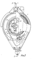
- the safety block represented in Figs. l to 3 comprises an aluminium alloy casing l within which a cable drum 2 is mounted for free rotation about a shaft 3 the ends of which are supported by the casing. At the top of the casing there is a shackle 4 by which the block can be suspended from a fixture.
- a cable 5 is wound onto the drum 2.
- the drum is formed in two parts 6, 7 which are secured together by bolts 8 after insertion of an end portion 9 of the cable in an arcuate groove l0 in the drum part 6.
- the groove is of tapered section and reduces in depth towards one end. By the tightening of bolts 8 the cable end portion becomes jammed tightly into the groove.
- the cable leads out of the casing l, from the drum, via a bottom aperture ll so that its free end can be attached to a person or object to be protected.
- the drum By pulling on the cable 5, the drum can be rotated in the unwinding direction, against the action of a spiral spring l2 housed within the drum part 7. So long as the unwinding speed remains below a certain level, the block offers virtually no resistance to the unwinding of the cable other than that imposed by the spring. However if the unwinding speed increases to that level, due for example to a person attached to the cable 5 falling, the drum becomes arrested by a friction brake (primary brake) through the agency of a centrifugal clutch mechanism as will now be described.
- a friction brake primary brake
- the primary brake is formed by a sandwich of four parts, namely a stainless steel pressure ring l3, a brass disc l4, an asbestos ring l5 and a part l6 of the block casing l. That part of the casing is provided wth a machined annular groove in which the asbestos ring l5 is seated.
- the said four brake parts are permanently clamped together by a series of bolts such as l7 which are angularly spaced around the assembly. The bolts connect the pressure ring l3 to the casing l and clamp the disc l4 and the asbestos ring l5 between those parts. Behind the heads of the bolts l7 there are spring washers (not shown).
- the bolts l7 are torqued to exert a clamping pressure such that if the brake comes into operation due to high acceleration of a body attached to the cable the body will be decelerated to zero within a short time without however being subjected to a harmful shock load.
- the bolts l7 are torqued to exert a clamping pressure of 0.6 Newton metres.
- the block complies with the British Standard performance specification BSS 5062 (l965). The block also meets the safety standard prescribed by DIN Standard 23 326.
- the disc l4 has an inner series of ratchet teeth l8 (Fig. 2).
- Two pawls l9,20 for engaging these teeth are pivotally connected to the drum part 6 by studs, one of which, designated 2l, appears in Fig. 2.
- the pawls are disposed to opposite sides of a diametral plane containing the drum axis and are interconnected by helical springs 22,23 which bias the springs radially inwardly about their pivots.
- the apparatus incorporates a fail-safe brake which becomes applied if a falling body is not arrested within a certain fall distance following application of the primary brake.
- This fail-safe brake comprises a phosphor bronze ring 24 which is in screw engagement with a socket 25 defined by a hub portion of the casing l.
- the ring 24 is coupled to the disc l4 of the primary brake by pins 26. These pins are secured to the disc l4 and intrude into blind bores in the phosphor bronze ring 24. The pins can therefore transmit a turning moment to ring 24 while allowing it to advance axially away from the disc l4 as necessitated by the threaded engagement between the ring 24 and the casing l.
- a spring steel brake disc 27 which is carried along the shaft 3 by the ring 24 when it becomes screwed along the socket 25.
- its spacing from the bottom of the socket 25 is such, (taking into account the pitch of the ring and socket threads) that in the event of the primary brake disc l4 being caused to turn, i.e. in the event of application of the primary brake, as a result of the fall of a person attached to the cable, the primary brake will in the normal way arrest the fall before spring steel brake disc 27 comes into contact with the casing l at the bottom of the socket 25.
- the ring 24 has an annular rebate groove 28 behind the inner margin of the brake disc 27.
- the casing l is shaped to provide a boss 29 opposite that groove. The initial contact of the disc 27 with the casing is between the inner margin of the disc and the said boss 29. Thereafter, as the ring 24 continues to be screwed into the socket, the disc 27 becomes deformed, its inner margin being deflected into the rebate groove 28. Following the initial contact there is accordingly a progressive build up of the braking force exerted by the fail-safe brake.
- the number of times which the fail-safe brake ring 24 has to be rotated in order to move it from its illustrated pre-set retracted position into an operative position in which it forces brake disc 27 against the boss 29 is more than twice the maximum number of times the disc l4 is liable to be rotated if the apparatus is subjected to British Standard fall-arrest test BSS 5062 (l965).
- BSS 5062 British Standard fall-arrest test
- the block incorporates an indicating device which gives a readable indication of the necessity or otherwise for the fail-safe brake ring 24 to be re-set.
- the indicating device comprises a pointer 30 which is mounted on a spindle 3l.
- the spindle is rotatably supported in the block casing l and carries, at its end within the casing, a sprocket 32.
- a pin 33 secured to the brake disc l4 is positioned so that it indexes this sprocket once during each revolution of that disc.
- Behind the pointer 30 is a dial 34 bearing markings which show the significance of the pointer position in terms of the position of the fail-safe brake ring 24. Inspection of the indicator accordingly suffices to determine whether re-setting of that ring is necessary.
- the block casing has to be opened by removing casing bolts such as 35 and removing what in the aspect of Fig. l is the right-hand casing section, together with the brake assemblies, from the shaft 3.
- the primary brake bolts l7 can then be loosened and the primary brake disc l4 rotated to retract the fail-safe brake ring.
- the illustrated embodiment also incorporates an audio-alarm device 36 which automatically sounds in the event of the primary brake being brought into use.
- the alarm device incorporates a micro-switch which is mounted to the block casing.
- a pin 37 is secured to the brake disc l4 and trips the micro-switch when or before the disc l4 has rotated through 360°.
- the block also incorporates mechanism enabling a weight suspended by the cable can be winched up towards the block.
- This mechanism comprises a winching handle 38 which is shown in Figs. l and 2 in a stowage position with its hand grip portion lying across the top portion of the block.
- the handle can be removed from its shaft 39 and reconnected thereto in a reversed, operative, position.
- a locking pin 40 (Fig. 3) intrudes into a circumferential groove on the shaft. This pin can be retracted to allow the handle with its shaft to be displaced axially (to the left in the aspect of Figs. l and 3).
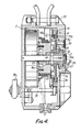
- FIG. 4 This apparatus is very similar to that illustrated in Figs. l to 3 and only certain parts of the Fig. 4 apparatus need be described. Parts corresponding with parts of the apparatus illustrated by Figs. l to 3 are indicated with the same reference numerals.
- the primary brake comprises a pressure ring l3, a disc l4, asbestos rings l5,l5a, a part l6 of the block casing l, and stainless steel washers l5b and l5c which are respectively interposed between the asbestos ring l5 and the pressure ring l3 and between the asbestos ring l5a and the casing part l6.
- the said brake parts are permanently clamped together by a series of bolts such as l7 which are angularly spaced around the assembly. The bolts connect the pressure ring l3 to the casing l and exert clamping pressure on the interposed parts.
- Pawls l9,20 are pivotally connected to the drum. If the drum accelerates in the unwinding direction due to the fall of a workman attached to the cable, the pawls pivot under the centrifugal force, against the action of springs, and free ends of the pawls are thereby caused to engage behind ratchet teeth of the disc l4 and this disc is consequently forced to rotate against the resistance imposed by the primary brake of which the disc l4 is a part. This resistance is such that the pay-out speed of the cable is decelerated to zero at a safe rate.
- the hand of the threads forming the screw connection is opposite to the hand of rotation of the drum 2 during pay-out of the cable 5.
- the ring 45 is keyed to the disc l4 of the primary brake.
- the key coupling comprises two diametrically opposed, axially directed ribs 46 on the ring 45 which engage keyways l4a in the disc l4.
- the disc l4 can therefore transmit a turning moment to ring 45 while allowing it to advance axially towards the drum 2 as necessitated by the threaded engagement between the ring 45 and the casing l.
- a spring steel brake disc 27 is fitted onto the ring 45. The inner margin of this disc overlies a rebate groove 47 in the ring 45.
- the primary brake disc l4 is shaped to provide an annular rib 48 which is located opposite to and is of slightly smaller width than the said rebate groove. In the event that the primary brake fails to arrest the fall within a predetermined maximum fall distance, the disc 27 abuts against the rib 48 and becomes deformed as the ring 45 continues to be screwed towards the drum. There is accordingly a progressive build up of the braking force exerted by the fail-safe brake.
- the torque resistance of the primary brake of the particular illustrated embodiment is such that the block meets the requirements of BSS 5062.
- the falling body is arrested within a free-fall distance of approximately 325 mm.
- the number of times which the fail-safe brake ring 45 has to be rotated in order to move it from its illustrated pre-set retracted position into the position in which the fail-safe braking action takes place, is more than five times the number of times that ring is rotated during such a fail-arrest test. In consequence, assuming that the primary brake functions properly, the block can be allowed to arrest several such falls in succession before it is necessary to open the casing and re-set the ring 24 to its fully retracted position.
- the indicating device comprising a pointer 30 for indicating the position of the fail-safe brake ring 45 is similar to that of the apparatus shown in Figs l-3.
- the dial behind the pointer bears markings which show the balance of the operational life of the apparatus before it has to be serviced by restoring the ring 45 to its fully retracted position.
- the dial has differently coloured sectors: a green sector, followed by am amber section, followed by a red section. After two or three falls arrested by the primary brake the pointer 30 will have moved from the green to the amber sector of the dial. After the arrest of two further falls by the primary brake, the pointer will have moved onto the red sector which is an indication that the apparatus must not be used again until it has been serviced.
- the block casing has to be opened by removing casing bolts such as 35 and removing what in the aspect of the drawing is the right-hand casing section, together with the brake assemblies, from the shaft 3.
- the primary brake bolts l7 can then be loosened and the ring l4 rotated to cause the fail-safe brake ring 45 to be screwed back into its fully retracted position..
- the block also incorporates a locking mechanism which locks the drum against rotation in the unwinding (cable pay-out) direction as soon as the fail-safe brake has been caused to function.
- This locking means is of a ratchet type.
- a pin 50 is mounted in a passageway extending through the fail-safe brake ring 45. This passageway is in spaced parallel relationship to the central bore of the ring, through which the drum shaft 3 extends. The pin is biased by a compression spring 50a into its illustrated advanced position in which the tips of the pin slightly projects from the inner end of the ring 45.
- a socket in which a machined insert 5l is secured.
- the exposed face of this insert is shaped to provide an inclined ramp whose course extends around the ring axis, the opposed ends of the ramp being bridged by a step.
- the fail-safe brake is brought into action, causing deformation of the steel brake disc 27, the projecting tip of the pin 50 comes into contact with the said ramp.
- the hand of inclination of the ramp is such that the drum can be turned by a winch in the re-wind direction so as to rewind the cable onto the drum but abutment of the pin against the step face prevents the drum from turning in the unwind direction. This locking device therefore ensures that the block cannot again be put to use until it has been serviced.
- Apparatus according to the invention can incorporate more than one primary friction brake.
- two primary friction brakes each comprising a component which is rotatable against a frictional resistance may be provided and these brakes can be actuatable via a common centrifugal clutch or via independent centrifugal clutches. If there is more than one primary friction brake they may be actuated by independent centrifugal clutches which are arranged so that they engage simultaneously or in succession during acceleration of the drum in the unwinding direction.
- Independent clutches may be provided for actuating one and the same primary friction brake.
- the clutches can be designed to engage at different rats of rotation of the drum.
- One clutch will then serve as a safety or back-up clutch which comes into operation in the event of unwinding acceleration of the drum beyond the speed at which the other clutch should have engaged.
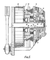
- Fig. 5 illustrates part of a safety apparatus according to the invention which incorporates independent clutches functioning in this manner.
- the construction of the apparatus is substantially the same as that of the apparatus according to Fig. 4 except in the following respect:
- the body of the drum 2 houses a co-axial insert 55 which has an integral spigot portion 56 which intrudes into the bore of the threaded fail-safe brake member 57.
- the body of the drum is rotatable relative to that insert and during normal rotations of the drum the insert remains stationary on the shaft 3.
- the spigot portion 56 has a spline connection with the threaded fail-safe brake member 57.
- the opposed larger end portion of the insert is recessed and is internally formed with peripheral ratchet teeth for engagement by pawls 58 which are pivotally mounted on the part of the drum which houses the return spring l2.
- the pawls are restrained against outward pivotal motion by springs (not shown) the strength of which is such that such pivotal motion occurs under centrifugal force at a drum speed somewhat higher than that at which the pawls l9/20 should engage the rotatable brake disc l4 and cause braking of the drum.
- springs not shown
- the strength of which is such that such pivotal motion occurs under centrifugal force at a drum speed somewhat higher than that at which the pawls l9/20 should engage the rotatable brake disc l4 and cause braking of the drum.
Landscapes
- Health & Medical Sciences (AREA)
- General Health & Medical Sciences (AREA)
- Business, Economics & Management (AREA)
- Emergency Management (AREA)
- Emergency Lowering Means (AREA)
- Braking Arrangements (AREA)
Applications Claiming Priority (4)
| Application Number | Priority Date | Filing Date | Title |
|---|---|---|---|
| GB8612945 | 1986-05-28 | ||
| GB868612945A GB8612945D0 (en) | 1986-05-28 | 1986-05-28 | Safety line drum |
| GB868630788A GB8630788D0 (en) | 1986-12-23 | 1986-12-23 | Safety line drum |
| GB8630788 | 1986-12-23 |
Publications (2)
| Publication Number | Publication Date |
|---|---|
| EP0247818A2 true EP0247818A2 (de) | 1987-12-02 |
| EP0247818A3 EP0247818A3 (de) | 1989-04-05 |
Family
ID=26290825
Family Applications (1)
| Application Number | Title | Priority Date | Filing Date |
|---|---|---|---|
| EP87304626A Withdrawn EP0247818A3 (de) | 1986-05-28 | 1987-05-26 | Vorrichtung zur Verhinderung von Abstürzen |
Country Status (4)
| Country | Link |
|---|---|
| US (1) | US4846313A (de) |
| EP (1) | EP0247818A3 (de) |
| AU (1) | AU589775B2 (de) |
| GB (1) | GB2192679B (de) |
Cited By (19)
| Publication number | Priority date | Publication date | Assignee | Title |
|---|---|---|---|---|
| WO1991011217A1 (en) * | 1990-01-27 | 1991-08-08 | Denis Ferranti Meters Limited | Safety device |
| GB2214249B (en) * | 1988-01-13 | 1991-12-04 | Hugh Willaim Skipper | Variable centrifugal brake. |
| WO1994019064A1 (en) * | 1993-02-18 | 1994-09-01 | Easytech, Coöperatieve Vennootschap. | Climbing safety device |
| WO2005025678A1 (en) * | 2003-09-05 | 2005-03-24 | D B Industries, Inc. | Self-retracting lifeline |
| WO2009047541A3 (en) * | 2007-10-12 | 2009-06-04 | Latchways Plc | Fall arrest system safety device |
| WO2009092438A1 (de) * | 2008-01-22 | 2009-07-30 | Cti Systems S.A. | Absturzsicherungsgerät mit seilantriebsmechanismus |
| EP2495017A1 (de) * | 2007-08-13 | 2012-09-05 | Checkmate Limited | Bremseinheit für Absturzsicherungsblock |
| US8567562B2 (en) | 2009-11-02 | 2013-10-29 | B D Industries, LLC | Brake assembly for a self-retracting lifeline assembly |
| US9121462B2 (en) | 2011-10-28 | 2015-09-01 | D B Industries, Llc | Self-retracting lifeline |
| US9174073B2 (en) | 2013-02-08 | 2015-11-03 | D B Industries, Llc | Energy absorber assembly and components thereof |
| WO2016089225A1 (en) | 2014-12-04 | 2016-06-09 | Eddy Current Limited Partnership | Latch activation between elements |
| CN108885225A (zh) * | 2015-12-18 | 2018-11-23 | 涡流有限合伙公司 | 一种用于动力系统的可变行为控制机构 |
| US10693360B2 (en) | 2014-12-04 | 2020-06-23 | Eddy Current Limited Partnership | Transmissions incorporating eddy current braking |
| US10873242B2 (en) | 2014-08-18 | 2020-12-22 | Eddy Current Limited Partnership | Tuning of a kinematic relationship between members |
| US10940339B2 (en) | 2014-12-04 | 2021-03-09 | Eddy Current Limited Partnership | Energy absorbing apparatus |
| US10971988B2 (en) | 2014-08-18 | 2021-04-06 | Eddy Current Limited Partnership | Latching devices |
| US11050336B2 (en) | 2014-12-04 | 2021-06-29 | Eddy Current Limited Partnership | Methods of altering eddy current interactions |
| US11114930B2 (en) | 2014-12-04 | 2021-09-07 | Eddy Current Limited Partnership | Eddy current brake configurations |
| US11515776B2 (en) | 2014-08-18 | 2022-11-29 | Eddy Current Limited Partnership | Tuning of a kinematic relationship between members |
Families Citing this family (34)
| Publication number | Priority date | Publication date | Assignee | Title |
|---|---|---|---|---|
| DE3910369A1 (de) * | 1989-03-28 | 1990-10-04 | Mannesmann Ag | Sicherheitseinrichtung |
| US4998683A (en) * | 1989-08-10 | 1991-03-12 | Hans Wendelborn | Spool and cord type safety device |
| US5147013A (en) * | 1990-10-29 | 1992-09-15 | Rose Manufacturing Company | Confined space entry apparatus |
| GB9023703D0 (en) * | 1990-10-31 | 1990-12-12 | Barrow Hepburn Sala Ltd | Fall-arrest apparatus |
| GB9027783D0 (en) * | 1990-12-21 | 1991-02-13 | Barrow Hepburn Sala Ltd | Safety anchorages for controlling pay-out of a safety line |
| US5553832A (en) * | 1993-03-12 | 1996-09-10 | Knight Industries, Inc. | Safety device for an air balancing hoist |
| US5722612A (en) * | 1994-01-18 | 1998-03-03 | Barrow Hepburn Sala Ltd. | Clutch mechanism for use in safety apparatus |
| US5511740A (en) * | 1994-03-31 | 1996-04-30 | Nordictrack, Inc. | Resistance mechanism for exercise equipment |
| NO952285L (no) * | 1995-06-09 | 1996-12-10 | Leksvik Production Group As | Anordning for nödslep av fartöyer |
| US6260667B1 (en) | 1999-04-15 | 2001-07-17 | Hamilton Sundstrand Corporation | Rotor containment brake |
| FR2828876B1 (fr) * | 2001-08-23 | 2004-01-16 | Aficor Sa | Treuil motorise |
| US7106205B2 (en) * | 2004-09-16 | 2006-09-12 | D B Industries, Inc. | Alarm device for use with fall protection equipment |
| US7226038B1 (en) * | 2005-03-25 | 2007-06-05 | Jon Wickstrom | Load arrestor, lifting system and method |
| US7849525B2 (en) * | 2006-04-12 | 2010-12-14 | Jamshid Ghajar | Apparatus for reducing brain and cervical spine injury due to rotational movement |
| KR100812970B1 (ko) | 2007-02-09 | 2008-03-12 | 주식회사 삼송 | 가속도감지를 통한 긴급잠금장치 |
| US20090064396A1 (en) * | 2007-04-11 | 2009-03-12 | Jamshid Ghajar | Apparatus for reducing brain and cervical spine injury due to rotational movement |
| US8834394B2 (en) | 2009-02-06 | 2014-09-16 | Jamshid Ghajar | Apparatus and methods for reducing brain and cervical spine injury |
| US10575979B2 (en) | 2009-02-06 | 2020-03-03 | Jamshid Ghajar | Subject-mounted device to measure relative motion of human joints |
| US10688323B2 (en) | 2009-03-09 | 2020-06-23 | D B Industries, Llc | Safety device with fall arrest and descending modes |
| EP2777771B1 (de) * | 2009-12-23 | 2022-05-04 | D B Industries, LLC | Sturzschutzvorrichtung mit einem Bremsmechanismus |
| USD656686S1 (en) | 2010-03-17 | 2012-03-27 | LynRus Aluminum Products, LLC | Auto-arresting safety device |
| US9309087B2 (en) * | 2013-06-20 | 2016-04-12 | Amx Llc | Retractable cable and cable rewind spool configuration |
| US10556138B2 (en) * | 2014-10-02 | 2020-02-11 | Honeywell International Inc. | Sealed self-retracting lifeline |
| GB2535142B (en) * | 2015-01-28 | 2020-07-29 | Latchways Plc | Energy absorber and fall arrest system safety device |
| US20160236018A1 (en) * | 2015-02-15 | 2016-08-18 | Aerohook Technology Co., Ltd. | Easy to Assemble Anti-dropping Device |
| CN105169575B (zh) * | 2015-08-20 | 2018-06-26 | 任远响 | 一种带有救援功能的逃生装置 |
| US9968804B2 (en) * | 2016-01-14 | 2018-05-15 | Reliance Industries, Llc | Nozzle for retractable fall arrest |
| US10265555B2 (en) * | 2016-06-17 | 2019-04-23 | Fang-Kuan Wu | Anti-falling device with rope retractable system |
| US9861841B1 (en) * | 2016-08-02 | 2018-01-09 | Yoke Industrial Corp. | Fall protection device |
| GB2556892B (en) * | 2016-11-23 | 2022-04-27 | Latchways Plc | Self-retracting lifeline fall arrest device |
| US20200023211A1 (en) * | 2018-07-20 | 2020-01-23 | Tian Hsing Chang | Fall protection device |
| TWI701061B (zh) * | 2019-06-25 | 2020-08-11 | 振鋒企業股份有限公司 | 鋼索式止墜器 |
| CN113491850B (zh) * | 2021-07-09 | 2022-04-22 | 安徽安兴装饰工程有限责任公司 | 一种用于室外装修的安全防护带 |
| WO2025015720A1 (zh) * | 2023-07-20 | 2025-01-23 | 中际联合(北京)科技股份有限公司 | 坠落防护装置 |
Family Cites Families (8)
| Publication number | Priority date | Publication date | Assignee | Title |
|---|---|---|---|---|
| US297126A (en) * | 1884-04-22 | Portable fire-escape | ||
| GB851981A (en) * | 1958-01-22 | 1960-10-19 | Sala Maskinfabriks Aktiebolag | Improvements in safety blocks |
| FR2165763A1 (de) * | 1971-12-28 | 1973-08-10 | Binaut Jean | |
| GB1463589A (en) * | 1974-12-12 | 1977-02-02 | Ex Proizv Razrabotke I Izgotov | Arrangement for protecting men working above ground against falling |
| US4216848A (en) * | 1977-09-06 | 1980-08-12 | Hitachi, Ltd. | Centrifugal braking device |
| GB1552667A (en) * | 1977-10-07 | 1979-09-19 | Barrow Hepburn Equip Ltd | Self winding drum |
| US4275803A (en) * | 1979-10-01 | 1981-06-30 | Harnischfeger Corporation | Load brake |
| US4489919A (en) * | 1983-03-21 | 1984-12-25 | Meyer Ostrobrod | Safety winch with disengageable drive |
-
1987
- 1987-05-26 GB GB8712358A patent/GB2192679B/en not_active Expired
- 1987-05-26 EP EP87304626A patent/EP0247818A3/de not_active Withdrawn
- 1987-05-27 AU AU73444/87A patent/AU589775B2/en not_active Expired - Fee Related
- 1987-05-28 US US07/055,067 patent/US4846313A/en not_active Expired - Fee Related
Cited By (50)
| Publication number | Priority date | Publication date | Assignee | Title |
|---|---|---|---|---|
| GB2214249B (en) * | 1988-01-13 | 1991-12-04 | Hugh Willaim Skipper | Variable centrifugal brake. |
| WO1991011217A1 (en) * | 1990-01-27 | 1991-08-08 | Denis Ferranti Meters Limited | Safety device |
| WO1994019064A1 (en) * | 1993-02-18 | 1994-09-01 | Easytech, Coöperatieve Vennootschap. | Climbing safety device |
| WO2005025678A1 (en) * | 2003-09-05 | 2005-03-24 | D B Industries, Inc. | Self-retracting lifeline |
| US7281620B2 (en) | 2003-09-05 | 2007-10-16 | D B Industries, Inc. | Self-retracting lifeline |
| EP2495017A1 (de) * | 2007-08-13 | 2012-09-05 | Checkmate Limited | Bremseinheit für Absturzsicherungsblock |
| US8991556B2 (en) | 2007-08-13 | 2015-03-31 | Checkmate Limited | Fall arrest block |
| US8950551B2 (en) | 2007-10-12 | 2015-02-10 | Latchways Plc | Fall arrest system safety device |
| WO2009047541A3 (en) * | 2007-10-12 | 2009-06-04 | Latchways Plc | Fall arrest system safety device |
| US10022573B2 (en) | 2007-10-12 | 2018-07-17 | Latchways Plc | Fall arrest system safety device |
| US10322306B2 (en) | 2007-10-12 | 2019-06-18 | Latchways Plc | Rotational energy absorber and fall arrest system |
| US8579086B2 (en) | 2008-01-22 | 2013-11-12 | Cti Systems S.A. | Crash safety device having a rope drive mechanism |
| CN101977657B (zh) * | 2008-01-22 | 2012-07-04 | Cti系统股份有限公司 | 带有绳索驱动机构的坠落保险装置 |
| WO2009092438A1 (de) * | 2008-01-22 | 2009-07-30 | Cti Systems S.A. | Absturzsicherungsgerät mit seilantriebsmechanismus |
| US8567562B2 (en) | 2009-11-02 | 2013-10-29 | B D Industries, LLC | Brake assembly for a self-retracting lifeline assembly |
| US9121462B2 (en) | 2011-10-28 | 2015-09-01 | D B Industries, Llc | Self-retracting lifeline |
| US9151349B2 (en) | 2011-10-28 | 2015-10-06 | D B Industries, Llc | Centrifugal brake assembly |
| US12005276B2 (en) | 2011-10-28 | 2024-06-11 | D B Industries, Llc | Centrifugal brake assembly |
| US9488235B2 (en) | 2011-10-28 | 2016-11-08 | D B Industries, Llc | Centrifugal brake assembly |
| US9889322B2 (en) | 2011-10-28 | 2018-02-13 | D B Industries, Llc | Centrifugal brake assembly |
| US10792523B2 (en) | 2011-10-28 | 2020-10-06 | 3M Innovative Properties Company | Centrifugal brake assembly |
| US9174073B2 (en) | 2013-02-08 | 2015-11-03 | D B Industries, Llc | Energy absorber assembly and components thereof |
| US10016638B2 (en) | 2013-02-08 | 2018-07-10 | D B Industries, Llc | Energy absorber assembly and components thereof |
| US11437903B2 (en) | 2014-08-18 | 2022-09-06 | Eddy Current Limited Partnership | Latching devices |
| US10971988B2 (en) | 2014-08-18 | 2021-04-06 | Eddy Current Limited Partnership | Latching devices |
| US11735992B2 (en) | 2014-08-18 | 2023-08-22 | Eddy Current Limited Partnership | Tuning of a kinematic relationship between members |
| US11632016B2 (en) | 2014-08-18 | 2023-04-18 | Eddy Current Limited Partnership | Tuning of a kinematic relationship between members |
| US10873242B2 (en) | 2014-08-18 | 2020-12-22 | Eddy Current Limited Partnership | Tuning of a kinematic relationship between members |
| US11515776B2 (en) | 2014-08-18 | 2022-11-29 | Eddy Current Limited Partnership | Tuning of a kinematic relationship between members |
| US11316404B2 (en) | 2014-08-18 | 2022-04-26 | Eddy Current Limited Partnership | Tuning of a kinematic relationship between members |
| US11777391B2 (en) | 2014-12-04 | 2023-10-03 | Eddy Current Limited Partnership | Methods of altering eddy current interactions |
| US11992713B2 (en) | 2014-12-04 | 2024-05-28 | Eddy Current Limited Partnership | Energy absorbing apparatus |
| US11050336B2 (en) | 2014-12-04 | 2021-06-29 | Eddy Current Limited Partnership | Methods of altering eddy current interactions |
| US11114930B2 (en) | 2014-12-04 | 2021-09-07 | Eddy Current Limited Partnership | Eddy current brake configurations |
| US12281681B2 (en) | 2014-12-04 | 2025-04-22 | Surewerx Usa, Inc. | Latch activation between members |
| US11009089B2 (en) | 2014-12-04 | 2021-05-18 | Eddy Current Limited Partnership | Latch activation between members |
| EP3226978B1 (de) * | 2014-12-04 | 2025-02-12 | SureWerx USA, Inc. | Verriegelungsaktivierung zwischen elementen |
| WO2016089225A1 (en) | 2014-12-04 | 2016-06-09 | Eddy Current Limited Partnership | Latch activation between elements |
| US11499596B2 (en) | 2014-12-04 | 2022-11-15 | Eddy Current Limited Partnership | Latch activation between members |
| US10940339B2 (en) | 2014-12-04 | 2021-03-09 | Eddy Current Limited Partnership | Energy absorbing apparatus |
| US12009721B2 (en) | 2014-12-04 | 2024-06-11 | Eddy Current Limited Partnership | Eddy current brake configurations |
| US10774887B2 (en) | 2014-12-04 | 2020-09-15 | Eddy Current Limited Partnership | Latch activation between members |
| US10693360B2 (en) | 2014-12-04 | 2020-06-23 | Eddy Current Limited Partnership | Transmissions incorporating eddy current braking |
| US10953848B2 (en) | 2015-12-18 | 2021-03-23 | Eddy Current Limited Partnership | Variable behavior control mechanism for a motive system |
| US11878651B2 (en) | 2015-12-18 | 2024-01-23 | Eddy Current Limited Partnership | Variable behavior control mechanism for a motive system |
| US20180370484A1 (en) * | 2015-12-18 | 2018-12-27 | Eddy Current Limited Partnership | A variable behavior control mechanism for a motive system |
| CN108885225A (zh) * | 2015-12-18 | 2018-11-23 | 涡流有限合伙公司 | 一种用于动力系统的可变行为控制机构 |
| AU2016372458B2 (en) * | 2015-12-18 | 2022-05-26 | Surewerx Usa, Inc. | A variable behaviour control mechanism for a motive system |
| CN108885225B (zh) * | 2015-12-18 | 2021-09-17 | 涡流有限合伙公司 | 一种用于动力系统的可变行为控制机构 |
| US12606124B2 (en) | 2015-12-18 | 2026-04-21 | Surewerx Usa, Inc. | Variable behavior control mechanism for a motive system |
Also Published As
| Publication number | Publication date |
|---|---|
| US4846313A (en) | 1989-07-11 |
| AU7344487A (en) | 1987-12-03 |
| GB8712358D0 (en) | 1987-07-01 |
| EP0247818A3 (de) | 1989-04-05 |
| AU589775B2 (en) | 1989-10-19 |
| GB2192679B (en) | 1989-12-13 |
| GB2192679A (en) | 1988-01-20 |
Similar Documents
| Publication | Publication Date | Title |
|---|---|---|
| US4846313A (en) | Fall-arrest apparatus | |
| EP0740570B1 (de) | Kupplungsmechanismus zum gebrauch in sicherheitsapparat | |
| US2990131A (en) | Safety block | |
| US4511123A (en) | Safety device | |
| US3946989A (en) | Slow descender including fluid and mechanical braking devices | |
| AU645364B2 (en) | Fall-arrest apparatus | |
| US4877110A (en) | Safety device with retractable lifeline | |
| EP2777771B1 (de) | Sturzschutzvorrichtung mit einem Bremsmechanismus | |
| EP2958635B1 (de) | Sturzsicherungsvorrichtung | |
| US5829548A (en) | Safety device inspection indicator | |
| EP2569056B1 (de) | Fallschutzanordnung | |
| US5343976A (en) | Safety device | |
| KR101376047B1 (ko) | 안전블럭의 제동장치 | |
| WO2021093180A1 (zh) | 一种缓冲式速差防坠器 | |
| GB2106855A (en) | A safety device | |
| US3701401A (en) | Torque overload sensing and indicating device for torque limiting brake mechanism | |
| EP0272908A2 (de) | Absturzsicherungsgerät | |
| GB2240757A (en) | Winched drum with safety devices | |
| JPS6323677A (ja) | 落下係止装置 | |
| GB2256413A (en) | Fall arrest device. | |
| WO1997026208A1 (en) | Automatic brake for winch of lift | |
| GB2074673A (en) | Overspeed safety braking device | |
| EP0787885B1 (de) | Vorrichtung zur Unfallverhütung zum Stoppen motorisierter Rolläden | |
| GB2256414A (en) | Fall arrest device. | |
| GB2279636A (en) | Indicating use of fall-arrest apparatus |
Legal Events
| Date | Code | Title | Description |
|---|---|---|---|
| PUAI | Public reference made under article 153(3) epc to a published international application that has entered the european phase |
Free format text: ORIGINAL CODE: 0009012 |
|
| AK | Designated contracting states |
Kind code of ref document: A2 Designated state(s): DE FR GB SE |
|
| PUAL | Search report despatched |
Free format text: ORIGINAL CODE: 0009013 |
|
| AK | Designated contracting states |
Kind code of ref document: A3 Designated state(s): DE FR GB SE |
|
| 17P | Request for examination filed |
Effective date: 19890911 |
|
| STAA | Information on the status of an ep patent application or granted ep patent |
Free format text: STATUS: THE APPLICATION HAS BEEN WITHDRAWN |
|
| 18W | Application withdrawn |
Withdrawal date: 19891009 |
|
| RIN1 | Information on inventor provided before grant (corrected) |
Inventor name: SHARP, GEORGE PATRICK |