EP0247751A2 - Videoanzeigesystem mit einem graphischer Cursor - Google Patents
Videoanzeigesystem mit einem graphischer Cursor Download PDFInfo
- Publication number
- EP0247751A2 EP0247751A2 EP87304097A EP87304097A EP0247751A2 EP 0247751 A2 EP0247751 A2 EP 0247751A2 EP 87304097 A EP87304097 A EP 87304097A EP 87304097 A EP87304097 A EP 87304097A EP 0247751 A2 EP0247751 A2 EP 0247751A2
- Authority
- EP
- European Patent Office
- Prior art keywords
- cursor
- data
- image
- display system
- video display
- Prior art date
- Legal status (The legal status is an assumption and is not a legal conclusion. Google has not performed a legal analysis and makes no representation as to the accuracy of the status listed.)
- Granted
Links
Images
Classifications
-
- G—PHYSICS
- G09—EDUCATION; CRYPTOGRAPHY; DISPLAY; ADVERTISING; SEALS
- G09G—ARRANGEMENTS OR CIRCUITS FOR CONTROL OF INDICATING DEVICES USING STATIC MEANS TO PRESENT VARIABLE INFORMATION
- G09G5/00—Control arrangements or circuits for visual indicators common to cathode-ray tube indicators and other visual indicators
- G09G5/08—Cursor circuits
Definitions
- This invention relates to a video display system having a graphical cursor. More specifically, the invention is concerned with the problem of superimposing a graphical cursor onto a raster-scanned video display, e.g. for a high-resolution interactive graphics workstation.
- each picture element (pixel) of the display is defined by the state of a single bit in the store (in the case of a monochrome display) or by the states of several bits (in the case of a grey-scale or colour display).
- data is read out of the store in synchronism with the raster scan of the display and converted to serial form to produce a video signal for driving the display.
- Such a display system normally has a pointing device in the form of a "mouse" or similar transducer, for pointing to, and drawing on the display.
- the physical movements of the mouse are translated into x-y coordinates defining the position of a graphical cursor within the display image.
- the cursor normally consists of a rectangular area within the displayed image in which the stored image is modified, according to a specified algorithm, by the contents of a cursor bit-map also held within the store.
- the cursor may, for example, consist of 64 ⁇ 64 pixels.
- the whole of the cursor data is read from the store into a fast static memory during the frame-blanking interval of the display, when the store video data port is otherwise unoccupied.
- the cursor data is then read out of the fast memory, converted to serial form, and aligned and combined with the serialised image data in real-time to produce an output video signal representing the image with the cursor superimposed at the required position.
- a video display system comprising:
- the cursor is read out of the store and combined with the image data on a line-by-line basis, rather than a whole frame at a time.
- the amount of fast storage required is greatly reduced, since the fast memory need only be capable of storing the portion of the cursor corresponding to a single raster line.
- the cursor data is pre-processed during the line-blanking interval so as to align it with respect to the image data, and the pre-processed cursor data is then combined with the image data, in real time during scanning of the next line of the display.
- the pre-processing of the cursor data and the combination of the pre-processed cursor data with the image data is performed in a bit-parallel manner (e.g. a byte at a time).
- a bit-parallel manner e.g. a byte at a time.
- the clock frequency is much lower than that required in a conventional display system where the data is handled serially (i.e. one bit at a time).
- only one parallel-to-serial converter is required, whereas in a conventional system two converters would be required, one for the image data and one for the cursor data.
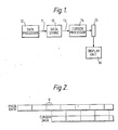
- FIG. l this shows an overall view of the video display system.
- the system includes a data store l0 which holds a bit map representing an image consisting of l024 ⁇ l024 pixels.
- the entire image therefore occupies l3l072 bytes of storage.
- the store l0 also holds a bit map representing a cursor to be superimposed on the image.
- the cursor consists of 64 ⁇ 64 pixels, each pixel being represented by two bits A,B.
- the cursor bit map consists of two 64 ⁇ 64 planes of data, containing two bits A,B for each of the pixels in the cursor. Each of these planes occupies 5l2 bytes of storage.
- the two bits A,B indicate the way in which the corresponding image pixel is to be modified by the cursor, as follows:
- the store has a byte-wide read/write port ll connected to a data processor l2, allowing the processor to read and write the image and cursor data as required.
- the store l0 also has a byte-wide read-only port l3, which is connected to a cursor processing unit l4.
- the unit l4 combines the cursor and image data read from the store to produce an output representing the image with the cursor superimposed on it in the required position.
- the output of the unit l4 is fed to an 8-bit shift register l5 which converts it from parallel to serial form.
- the serial output of the shift register is fed to the video input of a raster-scanned video display unit l6.
- FIG 2 shows image data representing one raster line of the image, consisting of a stream of l28 bytes.
- Figure 2 also shows the cursor data corresponding to this raster line, consisting of 8 bytes in each of the two cursor planes.
- One of the functions of the cursor processing unit l4, as will be described, is to pre-process the cursor so as to obtain the desired alignment with the image data.
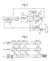
- Figure 3 shows the cursor processing unit in detail.
- This comprises a register file 30 which acts as a fast memory for buffering the cursor data.
- the register file has l8 eight-bit byte locations. Any two of these locations can be addressed simultaneously so as to read out two bytes in parallel from two output ports 3l,32.
- Such register files are well known in the art and so need not be described in further detail.
- a data byte from the output port l3 of the data memory l0 is applied to a barrel shifter 33, which performs a circular shift on each byte passing through it, so as to rotate it by a selected number of bit positions, from 0 to 7.
- the output of the barrel shifter 33 is fed to the data input of the register file 30 and can thus be written into any location of the register file.
- the outputs of the register file are connected to a pixel transformation circuit 34, which combines the cursor data with the image data.
- the circuit 34 consists of a set of eight OR gates 35 which combine the output of the first port 3l with the image data from the memory l0.
- the outputs of the OR gates 35 are combined with the output byte from the second port 32 by means of a set of eight exclusive OR gates 36.
- the outputs of the gates 36 are fed to the parallel-to-serial shift register l5 to produce the output video signal for the display.
- the outputs of the register file 30 are also fed to a mask and merge circuit 37.
- This consists of a set of eight AND gates 38 connected to the first output port 3l, and a set of eight AND gates 39 connected to the second output port 32.
- the AND gates 38 are controlled by an eight-bit mask held in a mask register 40, while the gates 39 are controlled by the inverse of the mask.
- the outputs of the two sets of AND gates are combined in a set of eight OR gates 4l, and the result is fed back to the input of the register file 30.
- the effect of the mask and merge circuit 37 is to select a group of bits as specified by the mask from the output port 3l, and a complementary group of bits from the other port 32, and to merge these together into a single byte.
- cursor data consists of 8 bytes from each of the two cursor planes (A,B).
- Figure 4a represents the eight bytes from one of these planes.
- the bytes of the cursor data may not match up with the image data bytes they are required to transform.
- the cursor data is matched with the image data as follows:
- each byte of the cursor data is rotated by an amount R corresponding to the offset between the cursor and image bytes.
- Figure 4b shows the result of this rotation.
- the cursor data in the register file is then processed by the mask and merge circuit 37, so as to merge the first R bits of each byte with the last N-R bits of the next byte.
- the last N-R bits are merged with an all-zero byte
- the first R bits are merged with an all-zero byte.
- the result of the mask and merge operation is written back into the register file.
- the register file now holds 9 bytes for each plane of the cursor, as shown in Figure 4c. It can be seen that the cursor data has been shifted R places to the right with respect to the byte boundaries and is therefore now correctly aligned with the image data. This operation is performed separately for each of the 2 planes (A,B).
- the image data corresponding to this line is read from the store l0, a byte at a time, in synchronism with the scan.
- reading of the cursor data from the register file commences.
- the cursor data is read out two bytes at a time, one byte from each of the two cursor planes (A,B) by way of the two register file output ports. These bytes are combined with the image data by means of the circuit 34, so as to modify the image data in accordance with the cursor.
Landscapes
- Engineering & Computer Science (AREA)
- Physics & Mathematics (AREA)
- Computer Hardware Design (AREA)
- General Physics & Mathematics (AREA)
- Theoretical Computer Science (AREA)
- Controls And Circuits For Display Device (AREA)
Applications Claiming Priority (2)
| Application Number | Priority Date | Filing Date | Title |
|---|---|---|---|
| GB8612930 | 1986-05-28 | ||
| GB868612930A GB8612930D0 (en) | 1986-05-28 | 1986-05-28 | Video display system |
Publications (3)
| Publication Number | Publication Date |
|---|---|
| EP0247751A2 true EP0247751A2 (de) | 1987-12-02 |
| EP0247751A3 EP0247751A3 (en) | 1989-08-02 |
| EP0247751B1 EP0247751B1 (de) | 1992-07-22 |
Family
ID=10598545
Family Applications (1)
| Application Number | Title | Priority Date | Filing Date |
|---|---|---|---|
| EP87304097A Expired EP0247751B1 (de) | 1986-05-28 | 1987-05-07 | Videoanzeigesystem mit einem graphischer Cursor |
Country Status (4)
| Country | Link |
|---|---|
| US (1) | US4768029A (de) |
| EP (1) | EP0247751B1 (de) |
| DE (1) | DE3780515T2 (de) |
| GB (1) | GB8612930D0 (de) |
Cited By (3)
| Publication number | Priority date | Publication date | Assignee | Title |
|---|---|---|---|---|
| WO1989006030A1 (en) * | 1987-12-24 | 1989-06-29 | Ncr Corporation | Apparatus for generating a cursor pattern on a display |
| EP0422300A1 (de) * | 1989-10-12 | 1991-04-17 | International Business Machines Corporation | Anzeigevorrichtung mit graphischem Cursor |
| GB2252224A (en) * | 1990-12-12 | 1992-07-29 | Apple Computer | Providing an overlay e.g. a cursor, for a computer display |
Families Citing this family (12)
| Publication number | Priority date | Publication date | Assignee | Title |
|---|---|---|---|---|
| US5276778A (en) * | 1987-01-08 | 1994-01-04 | Ezel, Inc. | Image processing system |
| US5553170A (en) * | 1987-07-09 | 1996-09-03 | Ezel, Inc. | High speed image processing system having a preparation portion and a converting portion generating a processed image based on the preparation portion |
| US5283866A (en) * | 1987-07-09 | 1994-02-01 | Ezel, Inc. | Image processing system |
| US4891631A (en) * | 1988-01-11 | 1990-01-02 | Eastman Kodak Company | Graphics display system |
| JPH03105385A (ja) * | 1989-09-20 | 1991-05-02 | Hitachi Ltd | 表示制御装置 |
| JP2554785B2 (ja) * | 1991-03-30 | 1996-11-13 | 株式会社東芝 | 表示駆動制御用集積回路及び表示システム |
| US5319384A (en) * | 1991-06-10 | 1994-06-07 | Symantec Corporation | Method for producing a graphical cursor |
| US5361081A (en) * | 1993-04-29 | 1994-11-01 | Digital Equipment Corporation | Programmable pixel and scan-line offsets for a hardware cursor |
| US6636198B1 (en) | 1997-04-15 | 2003-10-21 | Mercer Scientific International Corporation | Incremental controller for graphical displays |
| USD552115S1 (en) * | 2005-10-05 | 2007-10-02 | Olympus Imaging Corp. | Portion of interface for a digital camera having multiple selection icons |
| USD569872S1 (en) | 2005-11-29 | 2008-05-27 | Olympus Imaging Corp. | Interface for a digital camera having multiple selection icons |
| JP1525168S (de) * | 2014-08-19 | 2015-06-01 |
Family Cites Families (4)
| Publication number | Priority date | Publication date | Assignee | Title |
|---|---|---|---|---|
| GB2130855B (en) * | 1982-11-03 | 1986-06-04 | Ferranti Plc | Information display system |
| US4566000A (en) * | 1983-02-14 | 1986-01-21 | Prime Computer, Inc. | Image display apparatus and method having virtual cursor |
| JPS60247730A (ja) * | 1984-05-24 | 1985-12-07 | Matsushita Electric Ind Co Ltd | カ−ソル表示装置 |
| US4706074A (en) * | 1986-01-17 | 1987-11-10 | International Business Machines Corporation | Cursor circuit for a dual port memory |
-
1986
- 1986-05-28 GB GB868612930A patent/GB8612930D0/en active Pending
-
1987
- 1987-05-07 EP EP87304097A patent/EP0247751B1/de not_active Expired
- 1987-05-07 DE DE8787304097T patent/DE3780515T2/de not_active Expired - Fee Related
- 1987-06-01 US US07/056,588 patent/US4768029A/en not_active Expired - Fee Related
Cited By (4)
| Publication number | Priority date | Publication date | Assignee | Title |
|---|---|---|---|---|
| WO1989006030A1 (en) * | 1987-12-24 | 1989-06-29 | Ncr Corporation | Apparatus for generating a cursor pattern on a display |
| US4987551A (en) * | 1987-12-24 | 1991-01-22 | Ncr Corporation | Apparatus for creating a cursor pattern by strips related to individual scan lines |
| EP0422300A1 (de) * | 1989-10-12 | 1991-04-17 | International Business Machines Corporation | Anzeigevorrichtung mit graphischem Cursor |
| GB2252224A (en) * | 1990-12-12 | 1992-07-29 | Apple Computer | Providing an overlay e.g. a cursor, for a computer display |
Also Published As
| Publication number | Publication date |
|---|---|
| EP0247751B1 (de) | 1992-07-22 |
| GB8612930D0 (en) | 1986-07-02 |
| DE3780515T2 (de) | 1993-01-21 |
| DE3780515D1 (de) | 1992-08-27 |
| US4768029A (en) | 1988-08-30 |
| EP0247751A3 (en) | 1989-08-02 |
Similar Documents
| Publication | Publication Date | Title |
|---|---|---|
| US4876600A (en) | Method and device for representing a composite image on a screen of a screen device | |
| US5543824A (en) | Apparatus for selecting frame buffers for display in a double buffered display system | |
| EP0247751B1 (de) | Videoanzeigesystem mit einem graphischer Cursor | |
| US4168488A (en) | Image rotation apparatus | |
| US5694560A (en) | Workstation for displaying dynamic image with real-time special effects | |
| JP2656737B2 (ja) | ビデオ情報を処理するためのデータ処理装置 | |
| US5274753A (en) | Apparatus for distinguishing information stored in a frame buffer | |
| US5642498A (en) | System for simultaneous display of multiple video windows on a display device | |
| US5065346A (en) | Method and apparatus for employing a buffer memory to allow low resolution video data to be simultaneously displayed in window fashion with high resolution video data | |
| US5634089A (en) | Full color image ouput terminal interface | |
| US4862154A (en) | Image display processor for graphics workstation | |
| US4763119A (en) | Image processing system for area filling of graphics | |
| US4613852A (en) | Display apparatus | |
| JPS6055836B2 (ja) | ビデオ処理システム | |
| WO1980001422A1 (en) | Data processing system and apparatus for color graphics display | |
| US5258750A (en) | Color synchronizer and windowing system for use in a video/graphics system | |
| US4706074A (en) | Cursor circuit for a dual port memory | |
| JP2004280125A (ja) | ビデオ/グラフィックメモリシステム | |
| US4918526A (en) | Apparatus and method for video signal image processing under control of a data processing system | |
| US5313227A (en) | Graphic display system capable of cutting out partial images | |
| US5448264A (en) | Method and apparatus for separate window clipping and display mode planes in a graphics frame buffer | |
| EP0343636B1 (de) | Empfänger für Zeichenmultiplexrundfunk | |
| EP0525986A2 (de) | Gerät mit schneller Kopierung zwischen Rasterpuffern in einem Anzeigesystem mit Doppel-Pufferspeichern | |
| US5050102A (en) | Apparatus for rapidly switching between output display frames using a shared frame gentification memory | |
| EP0951694B1 (de) | Verfahren und gerät zur verwendung von interpolationszeilenpuffern als pixeltabellen |
Legal Events
| Date | Code | Title | Description |
|---|---|---|---|
| PUAI | Public reference made under article 153(3) epc to a published international application that has entered the european phase |
Free format text: ORIGINAL CODE: 0009012 |
|
| AK | Designated contracting states |
Kind code of ref document: A2 Designated state(s): DE FR GB IT NL |
|
| PUAL | Search report despatched |
Free format text: ORIGINAL CODE: 0009013 |
|
| AK | Designated contracting states |
Kind code of ref document: A3 Designated state(s): DE FR GB IT NL |
|
| 17P | Request for examination filed |
Effective date: 19890710 |
|
| 17Q | First examination report despatched |
Effective date: 19911113 |
|
| GRAA | (expected) grant |
Free format text: ORIGINAL CODE: 0009210 |
|
| AK | Designated contracting states |
Kind code of ref document: B1 Designated state(s): DE FR GB IT NL |
|
| PG25 | Lapsed in a contracting state [announced via postgrant information from national office to epo] |
Ref country code: IT Free format text: LAPSE BECAUSE OF FAILURE TO SUBMIT A TRANSLATION OF THE DESCRIPTION OR TO PAY THE FEE WITHIN THE PRE;WARNING: LAPSES OF ITALIAN PATENTS WITH EFFECTIVE DATE BEFORE 2007 MAY HAVE OCCURRED AT ANY TIME BEFORE 2007. THE CORRECT EFFECTIVE DATE MAY BE DIFFERENT FROM THE ONE RECORDED.SCRIBED TIME-LIMIT Effective date: 19920722 Ref country code: NL Effective date: 19920722 |
|
| REF | Corresponds to: |
Ref document number: 3780515 Country of ref document: DE Date of ref document: 19920827 |
|
| ET | Fr: translation filed | ||
| NLV1 | Nl: lapsed or annulled due to failure to fulfill the requirements of art. 29p and 29m of the patents act | ||
| PLBE | No opposition filed within time limit |
Free format text: ORIGINAL CODE: 0009261 |
|
| STAA | Information on the status of an ep patent application or granted ep patent |
Free format text: STATUS: NO OPPOSITION FILED WITHIN TIME LIMIT |
|
| 26N | No opposition filed | ||
| PGFP | Annual fee paid to national office [announced via postgrant information from national office to epo] |
Ref country code: FR Payment date: 19940531 Year of fee payment: 8 |
|
| PGFP | Annual fee paid to national office [announced via postgrant information from national office to epo] |
Ref country code: DE Payment date: 19940708 Year of fee payment: 8 |
|
| PG25 | Lapsed in a contracting state [announced via postgrant information from national office to epo] |
Ref country code: DE Effective date: 19960201 |
|
| PG25 | Lapsed in a contracting state [announced via postgrant information from national office to epo] |
Ref country code: FR Effective date: 19960229 |
|
| REG | Reference to a national code |
Ref country code: FR Ref legal event code: ST |
|
| REG | Reference to a national code |
Ref country code: FR Ref legal event code: ST |
|
| REG | Reference to a national code |
Ref country code: GB Ref legal event code: IF02 |
|
| PGFP | Annual fee paid to national office [announced via postgrant information from national office to epo] |
Ref country code: GB Payment date: 20020402 Year of fee payment: 16 |
|
| PG25 | Lapsed in a contracting state [announced via postgrant information from national office to epo] |
Ref country code: GB Free format text: LAPSE BECAUSE OF NON-PAYMENT OF DUE FEES Effective date: 20030507 |
|
| GBPC | Gb: european patent ceased through non-payment of renewal fee |
Effective date: 20030507 |