EP0246979A1 - Apparatus to preserve the sterility of a culture medium in an enclosure during sampling - Google Patents
Apparatus to preserve the sterility of a culture medium in an enclosure during sampling Download PDFInfo
- Publication number
- EP0246979A1 EP0246979A1 EP87401150A EP87401150A EP0246979A1 EP 0246979 A1 EP0246979 A1 EP 0246979A1 EP 87401150 A EP87401150 A EP 87401150A EP 87401150 A EP87401150 A EP 87401150A EP 0246979 A1 EP0246979 A1 EP 0246979A1
- Authority
- EP
- European Patent Office
- Prior art keywords
- chamber
- dilution
- piston
- sampling
- pistons
- Prior art date
- Legal status (The legal status is an assumption and is not a legal conclusion. Google has not performed a legal analysis and makes no representation as to the accuracy of the status listed.)
- Granted
Links
Images


Classifications
-
- G—PHYSICS
- G01—MEASURING; TESTING
- G01N—INVESTIGATING OR ANALYSING MATERIALS BY DETERMINING THEIR CHEMICAL OR PHYSICAL PROPERTIES
- G01N1/00—Sampling; Preparing specimens for investigation
- G01N1/02—Devices for withdrawing samples
- G01N1/10—Devices for withdrawing samples in the liquid or fluent state
-
- C—CHEMISTRY; METALLURGY
- C12—BIOCHEMISTRY; BEER; SPIRITS; WINE; VINEGAR; MICROBIOLOGY; ENZYMOLOGY; MUTATION OR GENETIC ENGINEERING
- C12M—APPARATUS FOR ENZYMOLOGY OR MICROBIOLOGY; APPARATUS FOR CULTURING MICROORGANISMS FOR PRODUCING BIOMASS, FOR GROWING CELLS OR FOR OBTAINING FERMENTATION OR METABOLIC PRODUCTS, i.e. BIOREACTORS OR FERMENTERS
- C12M33/00—Means for introduction, transport, positioning, extraction, harvesting, peeling or sampling of biological material in or from the apparatus
- C12M33/04—Means for introduction, transport, positioning, extraction, harvesting, peeling or sampling of biological material in or from the apparatus by injection or suction, e.g. using pipettes, syringes, needles
-
- C—CHEMISTRY; METALLURGY
- C12—BIOCHEMISTRY; BEER; SPIRITS; WINE; VINEGAR; MICROBIOLOGY; ENZYMOLOGY; MUTATION OR GENETIC ENGINEERING
- C12M—APPARATUS FOR ENZYMOLOGY OR MICROBIOLOGY; APPARATUS FOR CULTURING MICROORGANISMS FOR PRODUCING BIOMASS, FOR GROWING CELLS OR FOR OBTAINING FERMENTATION OR METABOLIC PRODUCTS, i.e. BIOREACTORS OR FERMENTERS
- C12M37/00—Means for sterilizing, maintaining sterile conditions or avoiding chemical or biological contamination
-
- Y—GENERAL TAGGING OF NEW TECHNOLOGICAL DEVELOPMENTS; GENERAL TAGGING OF CROSS-SECTIONAL TECHNOLOGIES SPANNING OVER SEVERAL SECTIONS OF THE IPC; TECHNICAL SUBJECTS COVERED BY FORMER USPC CROSS-REFERENCE ART COLLECTIONS [XRACs] AND DIGESTS
- Y10—TECHNICAL SUBJECTS COVERED BY FORMER USPC
- Y10T—TECHNICAL SUBJECTS COVERED BY FORMER US CLASSIFICATION
- Y10T137/00—Fluid handling
- Y10T137/8593—Systems
- Y10T137/86493—Multi-way valve unit
- Y10T137/86509—Sequentially progressive opening or closing of plural ports
-
- Y—GENERAL TAGGING OF NEW TECHNOLOGICAL DEVELOPMENTS; GENERAL TAGGING OF CROSS-SECTIONAL TECHNOLOGIES SPANNING OVER SEVERAL SECTIONS OF THE IPC; TECHNICAL SUBJECTS COVERED BY FORMER USPC CROSS-REFERENCE ART COLLECTIONS [XRACs] AND DIGESTS
- Y10—TECHNICAL SUBJECTS COVERED BY FORMER USPC
- Y10T—TECHNICAL SUBJECTS COVERED BY FORMER US CLASSIFICATION
- Y10T436/00—Chemistry: analytical and immunological testing
- Y10T436/11—Automated chemical analysis
- Y10T436/119163—Automated chemical analysis with aspirator of claimed structure
-
- Y—GENERAL TAGGING OF NEW TECHNOLOGICAL DEVELOPMENTS; GENERAL TAGGING OF CROSS-SECTIONAL TECHNOLOGIES SPANNING OVER SEVERAL SECTIONS OF THE IPC; TECHNICAL SUBJECTS COVERED BY FORMER USPC CROSS-REFERENCE ART COLLECTIONS [XRACs] AND DIGESTS
- Y10—TECHNICAL SUBJECTS COVERED BY FORMER USPC
- Y10T—TECHNICAL SUBJECTS COVERED BY FORMER US CLASSIFICATION
- Y10T436/00—Chemistry: analytical and immunological testing
- Y10T436/25—Chemistry: analytical and immunological testing including sample preparation
- Y10T436/2575—Volumetric liquid transfer
Definitions
- the present invention is in the field of taking samples in a sterile enclosure. More particularly, it uses a device making it possible to maintain the sterility of a culture medium in an enclosure during the taking of samples intended for analysis.
- One of the objects of the present invention is to provide a sampling device with which it is possible to carry out, in a reproducible manner, a sampling of known volume.
- Another object of the present invention is to provide a sampling device in which the known volume sampling is carried out online, while ensuring the non-contamination of the culture medium in which said sampling is carried out.
- Yet another object of the invention is to provide a sampling device ensuring the reduction of the risk of contamination of the fermentation thanks to the possibility of carrying out easy sterilization of the parts of the device involved in the sampling of a sample that is strictly constant in volume. , while allowing an automatic dilution of the sample taken by means of a solvent as well as the cooling of the mobile elements of the device and their drying by means of a sterile fluid.
- the present invention therefore relates to a device making it possible to maintain the sterility of a culture medium in an enclosure during the taking of samples intended for analysis, this device being characterized in that it includes, inside '' a frame, a first chamber, called the sampling chamber, in which slides a piston provided at one end with means allowing the sampling of a sample to be analyzed, this chamber extending by a nozzle intended to be inserted in a sealed manner in a nozzle provided on the enclosure containing the culture medium, and a second chamber, called dilution chamber, connected to the first chamber by a passage, this second chamber being divided into two zones by abutment means against which abut the at least two sliding pistons respectively in said zones, the first chamber having at least one outlet for the sample taken, while the second chamber has at least one o inlet port for a solvent.
- the sampling device is further remarkable by the following points: - sealing means are provided between the pistons and the corresponding chambers; - The piston of the first chamber has a shoulder in its zone opposite the sampling zone; - A stopper is provided in the second chamber, the volume of which is chosen so as to determine the dilution volume limited by the opposite faces of the pistons and the internal faces of said chamber; - The stopper is movable and actuated by external means, for example in stepper motor controlled by electronic means thus making it possible to adjust the dilution volume, therefore the dilution coefficient of the sample; the various pistons are actuated by motor means, for example, of the hydraulic, pneumatic or magnetic.
- a compressed air source is advantageously used, a plurality of distributing valves being provided and controlled by mechanical means, for example of the cam automaton type, or else by electro- computer, for example a microprocessor.
- the latter comprises two bodies secured to one another, for example by screwing, defining a first cylindrical chamber called sampling and a second cylindrical chamber known as dilution , in which one and three sliding pistons move respectively.
- This alternative embodiment is advantageously used by placing the sampling chamber in the upper position relative to the dilution chamber.
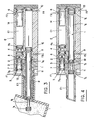
- the sampler E is mounted in a nozzle B of a fermenter Fe via a tip E1. It will be noted that the tapping B is directed obliquely upwards, relative to the wall of the fermenter, this inclination being intended to return the condensate towards the interior of the fermenter.
- the sampler consists of a frame E in which there has been arranged an upper chamber C1 and a lower chamber C2 extending by the nozzle E1.
- a piston 1 In the lower chamber C2, called the sampling chamber, is housed a piston 1 having in its end zone opposite the end piece E1 a shoulder 1 a .
- the piston At its other end, the piston is shaped so as to define a toroidal recess 1 b .
- Sealing means constituted by O-rings 1 c are provided on each side of the O-chamber 1 b .
- sealing means are also provided in the vicinity of the region of the shoulder 1 a, these sealing means are also constituted by O-rings 1 d.
- the dilution chamber C1 is provided with air intake orifices, 5, 6, according to the arrows f 1 , f 2 , with a steam intake orifice 7 according to the arrow f 3 and with an orifice. of dilution solvent 8.
- the C2 or sampling chamber is provided with two air intake-outlet orifices 9, 10, according to the arrows f 3 , f 4 , f 5 , f 6 , respectively.
- Chamber C2 is also provided with a purge orifice 11 according to arrow f 7 .
- the chambers C1 and C2 are joined by a passage or orifice 12.
- the sampler operates with a source of air com award winning S supplying by a series of valves V1, V2, V3, V5 the respective orifices 10, 9, 6, 5 by the respective conduits D1, D2, D3, D5.
- Compressed air is also admitted, on the one hand, through valve V4 and line C4 to a container R containing an appropriate solvent, for example water, a container in which the water subjected to the pressure of compressed air passes through the conduit D8 to the solvent intake port 8, and on the other hand, through the valve V6 and the conduit D6 to a filter Fi where the air being freed of its microorganisms and impurities is transferred to a mixing chamber Ch where this purified air is mixed with steam, the admission of which is controlled by a valve V7 via a conduit D7.
- the air-compressed / steam mixture is then brought by a duct D9 to the steam inlet orifice 8.
- valves V1 to V7 are advantageously solenoid valves controlled by a cam automaton Ac, itself actuated by a geared motor Mo and associated with pressure regulators M1 to M7. Downstream of the pressure regulators M1, M2, M3, lubricators L1, L2, L3 can be provided, this measurement is not however compulsory because the sampler according to the invention can also function efficiently, without the aid of lubrication agent.
- the operating cycle of the sampler according to the present invention is as follows: - when the sampler E is installed on the fermenter F, as shown in Figure 1, its operation can be broken down into five main operations as shown respectively in Figures 2 to 6.
- the first operation consists, before using the sampler, to sterilize the components contaminated by the external environment, for this purpose, the valves V3, V5, V6 and V7 are open, the other valves being closed, so as to, on the one hand, bring the pistons 3 and 4 into abutment against the stop 2, under the effect of the air admitted according to f1 and f2, in the chamber C1 while the mixture of filtered air coming from the filter f 1 and the steam are mixed in the chamber Ch before being admitted into the interior of the sampler through the intake orifice 8.
- the air / steam purge mixture then exits through the orifice 11 according to the arrow f 7 .
- the second operation consists in taking the sample.
- the valves V3 and V5 remain in the open state, while the valve V1 is opened so as to bring the sampling chamber 1b of the piston 1 inside the fermenter.
- the other valves V2, V4, V6 and V7 remain in the closed state.
- the third operation consists in bringing the sample back inside the sampler, and this, by closing the valve V1 and by opening the valve V2, the valves V3 and V5 always remaining closed, as well as the other valves.
- the air admitted according to f 5 through the orifice 9 acts on the shoulder 1a of the piston 1, to bring the latter into abutment against the wall of the chamber C1; this air flowing along f 6 through the orifice 10.
- the fourth operation represented by FIG. 5 consists in preparing a volume of solvent, for example water, intended for the dilution of the sample already taken according to the preceding operations.
- solvent for example water
- all the valves of the device are in the closed state, with the exception of valve V4 and valve V5.
- the compressed air pressure coming from the latter brings the piston 3 abutting against the stop 2, while the air pressure coming from the valve V4, causes, as described above, an inlet of solvent, for example from the water inside the chamber C2 through the inlet orifice 8.
- the opposite faces of the pistons 3 and 4 define with the internal faces of the chamber C1 a dilution volume becoming maximum when the piston 4 abuts against the stopper 14 of the bottom wall of said chamber C1.
- the fifth so-called “dilution-rinsing" operation consists in driving the duly diluted sample towards the analyzer, by opening the valve V3 which pushes the piston 4 abutting against the stop 2, while the piston 3 comes abutting against the opposite wall of the chamber C1, thus freeing the passage 12 between the chambers C1 and C2 in which the dilution-solvent liquid flows, which combining in the toric chamber 1 b flows towards the analyzer , not shown in the drawings, by the discharge or drain 11.
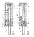
- the sterile sampler device consists of two bodies 101 and 102 connected together by screws.
- the body 101 acts as a tip and is fixed on the fermenter.
- a sealing plate 103 At the free end of the body 102 is provided a sealing plate 103.
- the assembly of the three elements 101, 102, 103 determines two cylindrical chambers, namely an upper or sampling chamber C3 and a lower chamber or dilution C4 .
- a sampling piston 104 capable of coming into abutment against an end plug 105 which seals the chamber C3.
- a piston called condensate 106 Inside the chamber C4 are mounted respectively three wandering pistons, namely a piston called condensate 106, a piston called steam 107 and a piston called diluent 108, the latter piston being liable to abut against a plug end 109 intended to seal the chamber C4.
- the piston 104 is in abutment on the right against the sealing plug 105.
- the piston 106 is pushed in abutment, on the left of the chamber C4, thus freeing the passage through the bores 110, 111.
- the piston 107 is pushed into abutment to the right of the zone 101 a of the chamber C3, on the shoulder of the chamber C3 thus freeing the passage through the bores 112, 113, while the piston 108 comes in abutment against the piston 107.
- the pressure at 114 is released before the end of the sterilization by atmospheric pressure to avoid that a slight leak in the seal of the C3 sampling chamber does not recontaminate the latter when the steam stops.
- the bores 116, 117 and 118 are at atmospheric pressure, while the solenoid valves associated with the bores 119 and 120 are closed. Steam is admitted through the orifice 120, it rises along the body of the piston 107, crosses the bore 112 then the sampling chamber of the piston 104 and is eliminated, as well as the condensates, according to the natural slope of sampling by the bore 110, then along the body of the piston 106 by the bore 111. After blowing the pressurization of the chamber for its rise in temperature is obtained by sequencing on a solenoid valve connected to the bore 111.
- the diameters of the bores and piston bodies are designed to allow easy passage of steam.
- the correct positioning of the piston 104 is ensured by the excitation of a stop sensor, not shown in the drawings, against the sealing plug 105.
- a stop sensor not shown in the drawings
- one proceeds, before the end of sterilization, to the filling of the water chamber of the sampling chamber C3 by an admission through the bore 120, considering that the bore 117 remains at atmospheric pressure from the sequence shown in Figure 7.
- the piston 108 then abuts against the sealing plug 109, while the piston 107 is not moved since it is maintained by the pressure of compressed air from the bore wise 114.
- a third operating sequence when the chamber sterilization time has elapsed, the system switches to the "sampling" position.
- the solenoid valve capable of occupying three positions, namely: admission of compressed air, bleeding, stopping, compressed air is admitted by bore 118
- the piston 104 releases the bore 112 which allows the vapor / air mixture to be filled with the chamber of the rod of the piston 104 (without evacuation) then releases the bore 110 which allows the establishment of a steam circuit through bores 122, 112, 110, 111 which sterilize the piston rod 104 as well as the chamber where it moves.
- the piston 104 therefore moves to the right.
- the control valve of the orifice 114 is brought to atmospheric pressure and l compressed air is sent through the orifice 116, causing the piston 106 to move to the right until it comes to a stop, as is more particularly shown in FIG. 11A.
- Bores 110 and 119 then communicate, the pressure 119 being atmospheric pressure.
- the piston 104 can then continue its course on the right until it comes into abutment with the sealing plug 105, as is more particularly shown in FIG. 11B.
- the residual pressure in the annular space of the piston 106 begins to expel the liquid along the path passing through the bores 112, 110, 119.
- the piston 104 should pause when the sampling chamber comes into communication with the orifice 110, this pause being used to move the piston 106 so as to avoid seeing the piston 104 reach its right position in abutment against the plug 105 while the piston 106 is always on the left and the piston 107 always on the right.
- a possible pressure imbalance between the respective annular spaces of the pistons 106 and 107 could then cause the liquid to flow back from the sampling chamber through the orifice 112 towards the bore 122.
- the sampler according to the present invention allows the control of the non-contamination of a culture medium by carrying out actual use cycles for several days. According to a preferred embodiment, it is possible, for example, to operate on a 20-liter fermenter, placed under normal culture conditions, with the notable exception of any intervention which may induce contamination and, of course, without innoculation. After normal fermentation, it will be possible, using the sampler according to the invention, to supply an analyzer, for example a device using the principle of enzyme electrodes, for rapidly carrying out assays of organic molecules in liquid medium. Any device, which by its design requires that it be supplied with samples of constant volume, is made particularly efficient thanks to its association with the sampler according to the present invention.
Abstract
Description
La présente invention est du domaine des prélèvements d'échantillons en enceinte stérile. Elle utilise plus particulièrement un dispositif permettant de conserver la stérilité d'un milieu de culture en enceinte pendant le prélèvement d'échantillons destinés à l'analyse.The present invention is in the field of taking samples in a sterile enclosure. More particularly, it uses a device making it possible to maintain the sterility of a culture medium in an enclosure during the taking of samples intended for analysis.
Jusqu'à présent, les dispositifs de la technique antérieure, qui étaient la plupart actionnés manuellement, ne permettaient pas de prélever des échantillons sans compromettre la stérilité du milieu de culture. Du fait que l'utilisateur devait faire son prélèvement manuellement, avec les multiples inconvénients que cela comporte, il était difficile de prélever des échantillons de volume difficilement contrôlable dont on ne pouvait en outre garantir l'absence de contamination par le milieu extérieur. Toutefois, un des risques les plus importants des dispositifs de la technique antérieure était celui de contaminer le contenu du fermenteur.Until now, the devices of the prior art, which were mostly operated manually, did not allow samples to be taken without compromising the sterility of the culture medium. Due to the fact that the user had to take his sample manually, with the multiple drawbacks that this entails, it was difficult to take samples of volume that was difficult to control, and the absence of contamination from the outside environment could not be guaranteed. However, one of the most important risks of the devices of the prior art was that of contaminating the content of the fermenter.
Un des objets de la présente invention est de fournir un dispositif de prélèvement avec lequel on peut effectuer de façon reproductible, un prélèvement de volume connu.One of the objects of the present invention is to provide a sampling device with which it is possible to carry out, in a reproducible manner, a sampling of known volume.
Un autre objet de la présente invention est de fournir un dispositif de prélèvement dans lequel le prélèvement de volume connu est effectué en ligne, tout en assurant la non-contamination du milieu de culture dans lequel est effectué ledit prélèvement.Another object of the present invention is to provide a sampling device in which the known volume sampling is carried out online, while ensuring the non-contamination of the culture medium in which said sampling is carried out.
Encore un autre objet de l'invention, est de réaliser un dispositif de prélèvement assurant la diminution des risques de contamination de la fermentation grâce à la possibilité de réaliser une stérilisation aisée des pièces du dispositif impliquées dans le prélèvement d'un échantillonde volume rigoureusement constant, tout en permettant une dilution automatique de l'échantillon prélevé au moyen d'un solvant ainsi que le refroidissement des éléments mobiles du dispositif et leur séchage au moyen d'un fluide stérile.Yet another object of the invention is to provide a sampling device ensuring the reduction of the risk of contamination of the fermentation thanks to the possibility of carrying out easy sterilization of the parts of the device involved in the sampling of a sample that is strictly constant in volume. , while allowing an automatic dilution of the sample taken by means of a solvent as well as the cooling of the mobile elements of the device and their drying by means of a sterile fluid.
La présente invention a donc pour objet un dispositif permettant de conserver la stérilité d'un milieu de culture en enceinte pendant le prélèvement d'échantillons destinés à l'analyse, ce dispositif étant caractérisé en ce qu'il comporte, à l'intérieur d'un bâti, une première chambre, dite de prélèvement, dans laquelle coulisse un piston pourvu à une extrémité de moyens permettant le prélèvement d'un échantillon à analyser, cette chambre se prolongeant par un embout destiné à venir s'insérer de façon étanche dans un piquage prévu sur l'enceinte renfermant le milieu de culture, et une seconde chambre, dite de dilution, reliée à la première chambre par un passage, cette seconde chambre étant divisée en deux zones par des moyens de butée contre lesquels viennent en aboutement au moins deux pistons coulissants respectivement dans lesdites zones, la première chambre présentant au moins un orifice de sortie pour l'échantillon prélevé, tandis que la seconde chambre comporte au moins un orifice d'admission pour un solvant.The present invention therefore relates to a device making it possible to maintain the sterility of a culture medium in an enclosure during the taking of samples intended for analysis, this device being characterized in that it includes, inside '' a frame, a first chamber, called the sampling chamber, in which slides a piston provided at one end with means allowing the sampling of a sample to be analyzed, this chamber extending by a nozzle intended to be inserted in a sealed manner in a nozzle provided on the enclosure containing the culture medium, and a second chamber, called dilution chamber, connected to the first chamber by a passage, this second chamber being divided into two zones by abutment means against which abut the at least two sliding pistons respectively in said zones, the first chamber having at least one outlet for the sample taken, while the second chamber has at least one o inlet port for a solvent.
Le dispositif de prélèvement selon la présente invention est en outre remarquable par les points suivants:
- on a prévu des moyens d'étanchéité entre les pistons et les chambres correspondantes;
- le piston de la première chambre présente dans sa zone opposée à la zone de prélèvement un épaulement;
- on a prévu dans la seconde chambre un butoir dont le volume et choisi de façon à déterminer le volume de dilution limité par les faces en regard des pistons et les faces internes de ladite chambre;
- le butoir est mobile et actionné par des moyens extérieurs, par exemple en moteur pas à pas commandé par des moyens électro-informatiques permettant ainsi de régler le volume de dilution, donc le coefficient de dilution de l'échantillon;
- les divers pistons sont actionnés par des moyens moteurs, par exemple, du type hydraulique, pneumatique ou magnétique. Dans le cas d'une commande pneumatique des pistons, on utilise avantageusement une source d'air comprimé, une pluralité de vannes distributrices étant prévues et commandées par des moyens mécaniques, par exemple du type automate à cames, ou bien par des moyens électro-informatiques, par exemple un micro-processeur.The sampling device according to the present invention is further remarkable by the following points:
- sealing means are provided between the pistons and the corresponding chambers;
- The piston of the first chamber has a shoulder in its zone opposite the sampling zone;
- A stopper is provided in the second chamber, the volume of which is chosen so as to determine the dilution volume limited by the opposite faces of the pistons and the internal faces of said chamber;
- The stopper is movable and actuated by external means, for example in stepper motor controlled by electronic means thus making it possible to adjust the dilution volume, therefore the dilution coefficient of the sample;
the various pistons are actuated by motor means, for example, of the hydraulic, pneumatic or magnetic. In the case of pneumatic control of the pistons, a compressed air source is advantageously used, a plurality of distributing valves being provided and controlled by mechanical means, for example of the cam automaton type, or else by electro- computer, for example a microprocessor.
Selon une autre variante de réalisation du dispositif de prélèvement selon la présente invention, ce dernier comporte deux corps solidarisés l'un à l'autre, par exemple par vissage, définissant une première chambre cylindrique dite de prélèvement et une seconde chambre cylindrique dite de dilution, dans lesquelles se déplacent respectivement un et trois pistons baladeurs. Cette variante de réalisation s'utilise avantageusement en disposant la chambre de prélèvement en position supérieure par rapport à la chambre de dilution.According to another alternative embodiment of the sampling device according to the present invention, the latter comprises two bodies secured to one another, for example by screwing, defining a first cylindrical chamber called sampling and a second cylindrical chamber known as dilution , in which one and three sliding pistons move respectively. This alternative embodiment is advantageously used by placing the sampling chamber in the upper position relative to the dilution chamber.
L'ensemble de ces modifications a pour but: d'assurer une meilleure stérilité du piston préleveur lorsqu'il pénètre dans le fermenteur, de garantir une bonne stérilisation; d'assurer une séparation entre les condensats de stérilisation et le liquide prélevé; de garantir une bonne exactitude de dilution; de diminuer les coûts des pièces en simplifiant l'usinage; et d'obtenir une stérilisation plus rapide et donc un échauffement global moindre.The purpose of all of these modifications is: to ensure better sterility of the sampling piston when it enters the fermenter, to guarantee good sterilization; to ensure a separation between the sterilization condensates and the withdrawn liquid; to guarantee good dilution accuracy; reduce parts costs by simplifying machining; and to obtain faster sterilization and therefore less overall heating.
Dans tous les cas, on a également prévu des moyens d'admission de solvant et des moyens permettant le balayage-nettoyage du dispositif de prélèvement, après chaque cycle de prélèvement.In all cases, there are also provided means for admitting solvent and means allowing the scanning-cleaning of the sampling device, after each sampling cycle.
D'autres avantages et caractéristiques de l'invention apparaîtront à la lecture de la description suivante, d'une forme de réalisation non limitative de dispositif de prélèvement, en référence aux dessins annexés, dans lesquels:
- Fig. 1 est une vue en coupe longitudinale axiale d'un dispositif de prélèvement ou échantillonneur selon l'invention, monté sur un piquage d'une enceinte de culture ou fermenteur;
- Fig. 2 est une vue plus en détail d'une coupe longitudinale axiale d'un échantillonneur selon l'invention, pendant la séquence de stérilisation;
- Fig. 3 est une vue analogue à la Figure 1 lors de la séquence de prélèvement de l'échantillon;
- Fig. 4 est une vue analogue aux Figures précédentes, lors de la séquence où l'échantillon est ramené dans l'échantillonneur;
- Fig. 5 est une vue analogue aux Figures précédentes, pendant la séquence de préparation du volume d'eau destiné à la dilution;
- Fig. 6 est une vue analogue aux Figures précédentes pendant la séquence de dilution-rinçage;
- Fig. 7 est une vue en coupe longitudinale axiale d'une variante de réalisation du dispositif échantillonneur de l'invention, pendant la séquence de stérilisation;
- Fig. 8 est une vue analogue à la Figure 1 pendant la séquence de fin de stérilisation-pré-prélèvement;
- Fig. 9 est une vue analogue à la Figure 1 pendant la séquence de prélèvement;
- Fig. 10 est une vue analogue à la Figure 1 pendant la séquence de fermeture d'admission de vapeur et fin de passage;
- Figs 11A et 11B sont respectivement des vues analogues à la Figure 1 pendant la séquence de dilution du liquide prélevé;
- Fig. 12 est une vue analogue à la Figure 1 de la séquence de fin de dilution.
- Figs 13A et 13B sont respectivement des vues analogues à la Figure 1 pendant la séquence et remise en position des pièces pour un nouveau cycle de stérilisation.
- Fig. 14 est un schéma d'ensemble du dispositif de prélèvement d'échantillon, selon l'invention.
- Fig. 1 is a view in axial longitudinal section of a sampling device or sampler according to the invention, mounted on a nozzle of a culture chamber or fermenter;
- Fig. 2 is a more detailed view of an axial longitudinal section of a sampler according to the invention, during the sterilization sequence;
- Fig. 3 is a view similar to FIG. 1 during the sample collection sequence;
- Fig. 4 is a view similar to the previous figures, during the sequence where the sample is returned to the sampler;
- Fig. 5 is a view similar to the previous figures, during the sequence of preparation of the volume of water intended for dilution;
- Fig. 6 is a view similar to the previous figures during the dilution-rinsing sequence;
- Fig. 7 is a view in axial longitudinal section of an alternative embodiment of the sampler device of the invention, during the sterilization sequence;
- Fig. 8 is a view similar to FIG. 1 during the end of sterilization-pre-sampling sequence;
- Fig. 9 is a view similar to FIG. 1 during the sampling sequence;
- Fig. 10 is a view similar to FIG. 1 during the sequence for closing the steam inlet and end of passage;
- Figs 11A and 11B are respectively views similar to Figure 1 during the dilution sequence of the sampled liquid;
- Fig. 12 is a view similar to FIG. 1 of the end of dilution sequence.
- Figs 13A and 13B are respectively views similar to Figure 1 during the sequence and repositioning of the parts for a new sterilization cycle.
- Fig. 14 is an overall diagram of the sample collection device according to the invention.
Comme représenté sur la Figure 1, l'échantilonneur E est monté dans un piquage B d'un fermenteur Fe par l'intermédiaire d'un embout E1. On notera que le piquage B est dirigé obliquement vers le haut, par rapport à la paroi du fermenteur, cette inclinaison étant destinée à renvoyer le condensat vers l'intérieur du fermenteur.As shown in Figure 1, the sampler E is mounted in a nozzle B of a fermenter Fe via a tip E1. It will be noted that the tapping B is directed obliquely upwards, relative to the wall of the fermenter, this inclination being intended to return the condensate towards the interior of the fermenter.
Comme représenté plus en détail sur les Figures 2 à 6, l'échantillonneur selon la présente invention est constitué d'un bati E dans lequel on a aménagé une chambre supérieure C1 et une chambre inférieure C2 se prolongeant par l'embout E1. Dans la chambre inférieure C2, dite de prélèvement, est logé un piston 1 présentant dans sa zone d'extrémité opposée à l'embout E1 un épaulement 1a. A son autre extrémité, le piston est conformé de façon à définir un évidement torique 1b. Des moyens d'étanchéité constitués par des joints toriques 1c sont prévus de chaque côté de la chambre torique 1b. De même des moyens d'étanchéité sont également prévus au voisinage de la zone de l'épaulement 1a, ces moyens d'étanchéité étant également constitués par des bagues toriques 1d. Dans la chambre supérieure C1 ou de dilution, sont montés de part et d'autre d'une butée centrale 2, deux pistons 3 et 4 pourvus respectivement dans leur zone d'extrémité de bagues toriques d'étanchéité 3a, 4a. La chambre de dilution C1 est pourvue d'orifices d'admission d'air, 5, 6, selon les flèches f1, f2, d'un orifice d'admission de vapeur 7 selon la flèche f3 et d'un orifice d'admission de solvant de dilution 8.As shown in more detail in Figures 2 to 6, the sampler according to the present invention consists of a frame E in which there has been arranged an upper chamber C1 and a lower chamber C2 extending by the nozzle E1. In the lower chamber C2, called the sampling chamber, is housed a
La chambre C2 ou de prélèvement est pourvue de deux orifices d'admission-sortie d'air 9, 10, selon les flèches f3, f4, f5, f6, respectivement. La chambre C2 est également pourvue d'un orifice de purge 11 selon la flèche f7. Les chambres C1 et C2 sont réunies par un passage ou orifice 12. Dans le schéma général de l'échantillonneur, selon l'invention telle que représenté sur la Figure 7, on voit que l'échantillonneur fonctionne avec une source d'air com primé S alimentant par une série de vannes V1, V2, V3, V5 les orifices respectifs 10, 9, 6, 5 par les conduits respectifs D1, D2, D3, D5. L'air comprimé est également admis, d'une part, par la vanne V4 et le conduit C4 à un récipient R renfermant un solvant approprié, par exemple de l'eau, un récipient dans lequel l'eau soumise à la pression d'air comprimé passe par le conduit D8 à l'orifice d'admission de solvant 8, et d'autre part, par la vanne V6 et le conduit D6 à un filtre Fi où l'air étant débarrassé de ses microorganismes et impuretés est transféré à une chambre de mélange Ch où cet air purifié vient se mélanger avec de la vapeur dont l'admission est commandée par une vanne V7 via un conduit D7. Le mélange air-comprimé/vapeur est ensuite amené par un conduit D9 à l'orifice d'admission de vapeur 8. Les vannes V1 à V7 sont avantageusement des électrovannes commandées par un automate à came Ac, lui-même actionné par un motoréducteur Mo et associées à des manodétendeurs M1 à M7. En aval des manodétendeurs M1, M2, M3, on peut prévoir des lubrificateurs L1, L2, L3, cette mesure n'est toutefois pas obligatoire car l'échantillonneur selon l'invention peut également fonctionner de façon performante, sans l'aide d'agent de lubrification.The C2 or sampling chamber is provided with two air intake-
Le cycle de fonctionnement de l'échantillonneur selon la présente invention est le suivant:
- lorsque l'échantillonneur E est implanté sur le fermenteur F, comme représenté sur la Figure 1, on peut décomposer son fonctionnement en cinq opérations principales comme représentées respectivement sur les Figures 2 à 6.
- comme représenté sur la Figure 2, la première opération consiste, avant utilisation de l'échantillonneur, à stériliser les éléments constitutifs contaminés par le milieu extérieur, à cet effet, les vannes V3, V5, V6 et V7 sont ouvertes, les autres vannes étant fermées, de façon à, d'une part, faire venir les pistons 3 et 4 en aboutement contre la butée 2, sous l'effet de l'air admis selon f1 et f2, dans la chambre C1 tandis que le mélange d'air filtré provenant du filtre f1 et la vapeur soient mélangés dans la chambre Ch avant d'être admis dans l'intérieur de l'échantillonneur par l'orifice d'admission 8. Le mélange air/vapeur de purge sort alors par l'orifice 11 selon la flèche f7.The operating cycle of the sampler according to the present invention is as follows:
- when the sampler E is installed on the fermenter F, as shown in Figure 1, its operation can be broken down into five main operations as shown respectively in Figures 2 to 6.
- As shown in Figure 2, the first operation consists, before using the sampler, to sterilize the components contaminated by the external environment, for this purpose, the valves V3, V5, V6 and V7 are open, the other valves being closed, so as to, on the one hand, bring the
La seconde opération, telle qu'illustrée sur la Figure 3, consiste à prélever l'échantillon. A cet effet, les vannes V3 et V5 restent à l'état ouvert, tandis que l'on ouvre la vanne V1 de façon à amener la chambre de prélèvement 1b du piston 1 à l'intérieur du fermenteur. Dans cette séquence, les autres vannes V2, V4, V6 et V7 restent à l'état fermé.The second operation, as illustrated in Figure 3, consists in taking the sample. To this end, the valves V3 and V5 remain in the open state, while the valve V1 is opened so as to bring the
La troisième opération, comme représentée sur la Figure 4, consiste à ramener l'échantillon à l'intérieur de l'échantillonneur, et ce, en fermant la vanne V1 et en ouvrant la vanne V2, les vannes V3 et V5 restant toujours fermées, de même que les autres vannes. L'air admis selon f5 par l'orifice 9 agit sur l'épaulement 1a du piston 1, pour ramener ce dernier en aboutement contre la paroi de la chambre C1; cet air s'écoulant selon f6 par l'orifice 10.The third operation, as shown in FIG. 4, consists in bringing the sample back inside the sampler, and this, by closing the valve V1 and by opening the valve V2, the valves V3 and V5 always remaining closed, as well as the other valves. The air admitted according to
La quatrième opération représentée par la Figure 5 consiste à préparer un volume de solvant, par exemple de l'eau, destiné à la dilution de l'échantillon déjà prélevé selon les opérations précédentes. A cet effet, toutes les vannes du dispositif sont à l'état fermé, à l'exception de la vanne V4 et de la vanne V5. La pression d'air comprimé issue de cette dernière amène le piston 3 en aboutement contre la butée 2, tandis que la pression d'air issue de la vanne V4, provoque, comme décrit ci-dessus, une arrivée de solvant, par exemple de l'eau à l'intérieur de la chambre C2 par l'orifice d'admission 8. On notera que les faces en regard des pistons 3 et 4 définissent avec les faces internes de la chambre C1 un volume de dilution devenant maximal lorsque le piston 4 vient en aboutement contre le butoir 14 de la paroi de fond de ladite chambre C1.The fourth operation represented by FIG. 5 consists in preparing a volume of solvent, for example water, intended for the dilution of the sample already taken according to the preceding operations. For this purpose, all the valves of the device are in the closed state, with the exception of valve V4 and valve V5. The compressed air pressure coming from the latter brings the
La cinquième opération dite de "dilution-rinçage" consiste à entraîner vers l'analyseur l'échantillon dûment dilué, et ce, par ouverture de la vanne V3 qui repousse le piston 4 en aboutement contre la butée 2, tandis que le piston 3 vient en aboutement contre la paroi opposée de la chambre C1, libérant ainsi le passage 12 entre les chambres C1 et C2 dans lequel s'écoule le liquide de dilution-solvant, qui se combinant dans la chambre torique 1b s'écoule vers l'analyseur, non représenté, sur les dessins, par l'orifice d'évacuation ou de purge 11.The fifth so-called "dilution-rinsing" operation consists in driving the duly diluted sample towards the analyzer, by opening the valve V3 which pushes the
Dans la variante de réalisation représentée sur les figures 7 à 13, le dispositif échantillonneur stérile selon l'invention est constitué de deux corps 101 et 102 reliés entre eux par des vis. Le corps 101 fait office d'embout et est fixé sur le fermenteur. A l'extrémité libre du corps 102 est prévue une plaque d'obturation 103. L'assemblage des trois éléments 101, 102, 103 détermine deux chambres cylindriques, à savoir une chambre supérieure ou de prélèvement C3 et une chambre inférieure ou de dilution C4. Dans la chambre supérieure C3 est monté un piston préleveur 104 susceptible de venir en aboutement contre un bouchon d'extrémité 105 qui assure l'étanchéité de la chambre C3. A l'intérieur de la chambre C4 sont montés respectivement trois pistons baladeurs, à savoir un piston dit de condensat 106, un piston dit de vapeur 107 et un piston dit de dilueur 108, ce dernier piston étant suceptible de venir en aboutement contre un bouchon d'extrémité 109 destiné à assurer l'étanchéité de la chambre C4.In the variant embodiment shown in FIGS. 7 to 13, the sterile sampler device according to the invention consists of two
Cette variante de réalisation d'échantillonneur stérile fonctionne de la manière suivante:This variant embodiment of sterile sampler operates as follows:
Dans une première séquence de fonctionnement, le piston 104 est en butée à droite contre le bouchon d'étanchéité 105. Le piston 106 est poussé en butée, à gauche de la chambre C4, libérant ainsi le passage par les alésages 110, 111. Le piston 107 est poussé en butée à droite de la zone 101a de la chambre C3, sur l'épaulement de la chambre C3 libérant ainsi le passage par les alésages 112, 113, tandis que le piston 108 vient en butée contre le piston 107. Ces positions sont obtenues sous l'effet de la pression d'air comprimé appliqué par les orifices 114 et 115. La pression en 114 est relâchée avant la fin de la stérilisation par mise à pression atmosphérique pour éviter qu'une légère fuite du joint de la chambre de prélèvement C3 ne vienne recontaminer celle-ci à l'arrêt de la vapeur. Les alésages 116, 117 et 118 sont à pression atmosphérique, tandis que les électrovannes associées aux alésages 119 et 120 sont fermées. La vapeur est admise par l'orifice 120, elle remonte le long du corps du piston 107, traverse l'alésage 112 puis la chambre de prélèvement du piston 104 et s'élimine, ainsi que les condensats, selon la pente naturelle de prélèvement par l'alésage 110, puis le long du corps du piston 106 par l'alésage 111. Après soufflage la pressurisation de la chambre pour sa montée en température est obtenue par séquencement sur une électrovanne branchée sur l'alésage 111. Les diamètres des alésages et des corps de piston sont étudiés pour permettre un passage aisé de la vapeur. Pour la stérilisation de la chambre de prélèvement, le positionnement correct du piston 104 est assuré par l'excitation d'un capteur de butée, non représenté aux dessins, contre le bouchon d'étanchéité 105. Dans la seconde séquence de fonctionnement représentée sur la Figure 8, on procède, avant la fin de la stérilisation, au remplissage de la chambre à eau de la chambre de prélèvement C3 par une admission à travers l'alésage 120, en considérant que l'alésage 117 reste sous pression atmosphérique depuis la séquence de fonctionnement représentée sur la Figure 7. Le piston 108 vient alors en butée contre le bouchon d'étanchéité 109, tandis que le piston 107 n'est pas déplacé puisqu'il est maintenu par la pression d'air comprimé provenant de l'alé sage 114.In a first operating sequence, the
Dans une troisième séquence de fonctionnement, lorsque le temps de stérilisation de la chambre est écoulé, le système passe en position "prélèvement". Après la fermeture de l'électrovanne associée à l'alésage 115, l'électrovanne susceptible d'occuper trois positions, à savoir: admission de l'air comprimé, purge, arrêt, de l'air comprimé est admis par l'alésage 118. Lors de son avancée, le piston 104 libère l'alésage 112 qui permet le remplissage en mélange vapeur/air de la chambre de la tige du piston 104 (sans évacuation) puis libère l'alésage 110 qui permet l'établissement d'un circuit de vapeur par les alésages 122, 112, 110, 111 qui stérilisent la tige du piston 104 ainsi que la chambre où elle se déplace. Selon la séquence de fonctionnement 4 représentée sur la Figure 9, lorsque le piston 104 arrive en fin de course gauche, en butée sur l'épaulement de la chambre C3, il est possible d'arrêter le passage de la vapeur. L'électrovanne admettant celle-ci à l'orifice 122 est alors fermée après celle de purge à l'orifice 111.In a third operating sequence, when the chamber sterilization time has elapsed, the system switches to the "sampling" position. After closing the solenoid valve associated with
Dans la séquence de fonctionnement représentée sur les Figures 11A et 11B, l'alésage 118 est alors mis à pression atmosphérique et de l'air comprimé est admis par l'alésage 115 provoquant le retrait du piston 104 et la mise en pression d'air comprimé des chambres respectives des pistons 106 et 107.In the operating sequence shown in Figures 11A and 11B, the
Le piston 104 se déplace donc vers la droite. Dès que la chambre de prélèvement débouche dans l'alésage 110, ce qui est détecté par un capteur de position, non représenté aux dessins, du piston 104, la vanne de commande de l'orifice 114 se met à la pression atmosphérique et de l'air comprimé est envoyé par l'orifice 116, provoquant le déplacement du piston 106 sur la droite jusqu'à venir en butée, comme cela est plus particulièrement représenté sur la Figure 11A. Les alésages 110 et 119 communiquent alors, la pression 119 étant la pression atmosphérique. Le piston 104 peut alors continuer sa course sur la droite jusqu'à rentrer en butée avec le bouchon d'étanchéité 105, comme cela est plus particulièrement représenté sur la Figure 11B. La pression résiduelle dans l'espace annulaire du piston 106 commence à chasser le liquide selon le trajet passant par les alésages 112, 110, 119. Il convient que le piston 104 marque une pause au moment où la chambre de prélèvement rentre en communication avec l'orifice 110, cette pause étant utilisée pour faire déplacer le piston 106 de façon à éviter de voir le piston 104 atteindre sa position droite en butée contre le bouchon 105 alors que le piston 106 est toujours à gauche et le piston 107 toujours à droite. Un éventuel déséquilibre de pression entre les espaces annulaires respectifs des pistons 106 et 107 pourrait alors faire refluer le liquide de la chambre de prélèvement au travers de l'orifice 112 vers l'alésage 122.The
Dans la séquence de fonctionnement représenté sur la Figure 12, de l'air comprimé est alors envoyé par l'alésage 117, alors que la pression est toujours maintenue en 116, provoquant, sous la poussée du piston 108, une avancée de la colonne liquide qui déplace le piston 107 et libère l'alésage 112, le piston 107 venant alors en butée contre le piston 106. Le liquide passe donc dans la chambre de prélèvement, reflue par l'alésage 110 et s'échappe par l'alésage 119. L'extrémité du piston 108 vient alors s'emboîter dans la zone d'épaulement de la chambre C4.In the operating sequence shown in Figure 12, compressed air is then sent through the
Dans la séquence de fonctionnement représentée sur les Figures 13A et 14A, il est possible de commencer un nouveau cycle de stérilisation, étant donné que le cycle de dilution est terminé. Pour ce faire, l'alésage 116 est mis à la pression atmosphérique. La mise en pression de l'alésage 114 provoque le positionnement du piston 106 en position de stérilisation, le trajet par les alésages 110 et 111 étant rendu libre. Le piston 107 est maintenu par le piston 108 comme représenté plus spécialement sur la Figure 13A. L'alésage 117 est alors mis sous pression atmosphérique. Le piston 107 repousse le piston 108 et libère le trajet passant par les alésages 122 et 112 d'arrivée de vapeur. Il est important que l'alésage 119 soit alors condamné avant que le passage passant par les alésages 122, 112 soit ouvert, de façon à éliminer le risque d'introduction de vapeur dans le prélèvement, ladite vapeur étant alors admise par la vanne associée à l'alésage 122, comme cela est plus particulièrement représenté sur la Figure 13B. L'opérateur se retrouve alors dans la situation lui permettant de réaliser la séquence 1.In the operating sequence shown in Figures 13A and 14A, it is possible to start a new sterilization cycle, since the dilution cycle has ended. To do this, the
L'échantillonneur selon la présente invention permet le contrôle de la non-contamination d'un milieu de culture en réalisant des cycles d'utilisation réelle pendant plusieurs jours. Selon un mode de réalisation préféré, on peut par exemple opérer sur un fermenteur de 20 litres, placé dans les conditions de culture normale, à l'exception notable de toute intervention pouvant induire une contamination et, bien entendu, sans innoculation. Après fermentation normale, on pourra, en utilisant l'échantillonneur selon l'invention, alimenter un analyseur, par exemple un appareil utilisant le principe des électrodes à enzyme, pour effectuer rapidement des dosages de molécules organiques en milieu liquide. Tout appareil, qui par sa conception nécessite qu'on lui fournisse des échantillons de volume constant, est rendu particulièrement performant grâce à son association avec l'échantillonneur selon la présente invention. On notera que la présente invention n'a été rendue possible que par la collaboration active entre le laboratoire de technologie enzymatique de l'Université Technologique de Compiègne, laboratoire associé au Centre National de la Recherche Scientifique N.338, et les inventeurs. Ainsi se trouve résolu, selon la présente invention, le problème de l'échantillonnage automatique respectant le milieu dans lequel l'échantillon est prélevé et ce, en obtenant des volumes constants à partir desquels on peut réaliser les différentes opérations d'analyse désirées.The sampler according to the present invention allows the control of the non-contamination of a culture medium by carrying out actual use cycles for several days. According to a preferred embodiment, it is possible, for example, to operate on a 20-liter fermenter, placed under normal culture conditions, with the notable exception of any intervention which may induce contamination and, of course, without innoculation. After normal fermentation, it will be possible, using the sampler according to the invention, to supply an analyzer, for example a device using the principle of enzyme electrodes, for rapidly carrying out assays of organic molecules in liquid medium. Any device, which by its design requires that it be supplied with samples of constant volume, is made particularly efficient thanks to its association with the sampler according to the present invention. It will be noted that the present invention was made possible only by the active collaboration between the laboratory of enzymatic technology of the Technological University of Compiègne, laboratory associated with the National Center of Scientific Research N.338, and the inventors. Thus is solved, according to the present invention, the problem of automatic sampling respecting the environment in which the sample is taken, obtaining constant volumes from which the various desired analysis operations can be carried out.
Il est clair que la présente invention n'est nullement limitée à la forme de réalisation décrite ci-dessus en référence aux dessins annexés, mais qu'elle englobe toutes les modifications et variantes à la portée de l'homme de l'art. C'est ainsi que l'on peut modifier à volonté la forme des pistons, les rendre télescopiques ou à géométrie variable, tout en respectant les conditions d'étanchéité nécessaires à l'intérieur des chambres. De même, si l'on a utilisé des moyens pneumatiques, il n'en reste pas moins que n'importe quel moyen d'actionnement peut être utilisé à condition toutefois, de respecter les conditions d'étanchéité et de stérilité nécessaires au bon fonctionnement du dispositif de l'invention.It is clear that the present invention is in no way limited to the embodiment described above with reference to the accompanying drawings, but that it encompasses all modifications and variants within the reach of ordinary skill in the art. This is how the shape of the pistons can be modified at will, making them telescopic or of variable geometry, while respecting the necessary sealing conditions inside the chambers. Likewise, if pneumatic means have been used, the fact remains that any actuating means can be used provided, however, that the sealing and sterility conditions necessary for proper functioning are respected of the device of the invention.
Claims (13)
Priority Applications (1)
| Application Number | Priority Date | Filing Date | Title |
|---|---|---|---|
| AT87401150T ATE57768T1 (en) | 1986-05-22 | 1987-05-21 | DEVICE FOR MAINTAINING THE STERILITY OF A CULTURE MEDIUM IN A CONTAINER DURING SAMPLING. |
Applications Claiming Priority (2)
| Application Number | Priority Date | Filing Date | Title |
|---|---|---|---|
| FR8607329 | 1986-05-22 | ||
| FR8607329A FR2599148B1 (en) | 1986-05-22 | 1986-05-22 | DEVICE FOR MAINTAINING THE STERILITY OF AN ENCLOSED CULTURE MEDIUM DURING SAMPLING |
Publications (2)
| Publication Number | Publication Date |
|---|---|
| EP0246979A1 true EP0246979A1 (en) | 1987-11-25 |
| EP0246979B1 EP0246979B1 (en) | 1990-10-24 |
Family
ID=9335503
Family Applications (1)
| Application Number | Title | Priority Date | Filing Date |
|---|---|---|---|
| EP87401150A Expired - Lifetime EP0246979B1 (en) | 1986-05-22 | 1987-05-21 | Apparatus to preserve the sterility of a culture medium in an enclosure during sampling |
Country Status (7)
| Country | Link |
|---|---|
| US (1) | US4957706A (en) |
| EP (1) | EP0246979B1 (en) |
| AT (1) | ATE57768T1 (en) |
| DE (1) | DE3765694D1 (en) |
| ES (1) | ES2018032B3 (en) |
| FR (1) | FR2599148B1 (en) |
| GR (1) | GR3001139T3 (en) |
Families Citing this family (12)
| Publication number | Priority date | Publication date | Assignee | Title |
|---|---|---|---|---|
| FR2652897B1 (en) * | 1989-10-10 | 1994-01-07 | Institut Francais Petrole | DEVICE AND METHOD FOR TRANSFERRING A SAMPLE OF FLUID BETWEEN TWO CHAMBERS AND APPLICATION IN PARTICULAR TO GAS CHROMATOGRAPHY. |
| US5384095A (en) * | 1990-08-08 | 1995-01-24 | ANDOS Technik fur die Medizin GmbH | Apparatus for the transfer of a defined specimen quantity from an outer space into a test chamber |
| US5150601A (en) * | 1990-12-21 | 1992-09-29 | The Dow Chemical Company | Fluid sampling for gas chromatograph with modified sampling valve |
| CA2088682A1 (en) * | 1991-06-18 | 1992-12-19 | Nicolae Paraschiv | Demountable, replaceable aspirating needle cartridge assembly |
| FR2704757B1 (en) * | 1993-05-07 | 1995-08-11 | Framatome Sa | Device for high pressure sterilization of products. |
| US5730938A (en) * | 1995-08-09 | 1998-03-24 | Bio-Chem Laboratory Systems, Inc. | Chemistry analyzer |
| US6258324B1 (en) | 1999-03-15 | 2001-07-10 | Felix H. Yiu | Pipette dispensing block |
| US6951545B2 (en) * | 2001-12-04 | 2005-10-04 | Lifepoint, Inc. | Integral sample collection tip |
| US7549349B2 (en) * | 2006-06-22 | 2009-06-23 | Evogen, Inc. | Sample cartridge for air-sampling device |
| US8312780B2 (en) | 2010-06-25 | 2012-11-20 | Mettler-Toledo Ag | Sampling device and method |
| US8365617B2 (en) * | 2010-06-25 | 2013-02-05 | Mettler-Toledo Ag | Sampling device |
| US9410871B1 (en) * | 2012-10-22 | 2016-08-09 | A+ Manufacturing, Llc | Apparatus for analytical sampling and/or conditioning of a process gas with selective isolation capability, and method therefore |
Citations (4)
| Publication number | Priority date | Publication date | Assignee | Title |
|---|---|---|---|---|
| US3746217A (en) * | 1971-09-07 | 1973-07-17 | E Hanset | Measuring system |
| FR2250109A1 (en) * | 1973-11-05 | 1975-05-30 | Commissariat Energie Atomique | |
| FR2524144A1 (en) * | 1982-03-24 | 1983-09-30 | Inst Rech Hydrologiques | Constant vol. liq. sampling appts. - has piston in cylindrical case movable between two positions with sample expulsion by compressed air |
| DE3338782A1 (en) * | 1983-10-26 | 1985-05-15 | Sartorius GmbH, 3400 Göttingen | Apparatus for the aseptic sampling of liquids from a pipe, in particular in the beverage, pharmaceutical and cosmetics industry |
Family Cites Families (3)
| Publication number | Priority date | Publication date | Assignee | Title |
|---|---|---|---|---|
| US4585623A (en) * | 1984-02-27 | 1986-04-29 | Allelix Inc. | Device for performing quantitative chemical and immunochemical assays |
| US4649028A (en) * | 1985-03-27 | 1987-03-10 | Medica Corporation | Electrolyte analyzer |
| US4640821A (en) * | 1985-07-16 | 1987-02-03 | Fisher Scientific Company | Analysis apparatus |
-
1986
- 1986-05-22 FR FR8607329A patent/FR2599148B1/en not_active Expired
-
1987
- 1987-05-21 AT AT87401150T patent/ATE57768T1/en not_active IP Right Cessation
- 1987-05-21 EP EP87401150A patent/EP0246979B1/en not_active Expired - Lifetime
- 1987-05-21 US US07/052,409 patent/US4957706A/en not_active Expired - Fee Related
- 1987-05-21 ES ES87401150T patent/ES2018032B3/en not_active Expired - Lifetime
- 1987-05-21 DE DE8787401150T patent/DE3765694D1/en not_active Expired - Fee Related
-
1990
- 1990-11-30 GR GR90401003T patent/GR3001139T3/en unknown
Patent Citations (4)
| Publication number | Priority date | Publication date | Assignee | Title |
|---|---|---|---|---|
| US3746217A (en) * | 1971-09-07 | 1973-07-17 | E Hanset | Measuring system |
| FR2250109A1 (en) * | 1973-11-05 | 1975-05-30 | Commissariat Energie Atomique | |
| FR2524144A1 (en) * | 1982-03-24 | 1983-09-30 | Inst Rech Hydrologiques | Constant vol. liq. sampling appts. - has piston in cylindrical case movable between two positions with sample expulsion by compressed air |
| DE3338782A1 (en) * | 1983-10-26 | 1985-05-15 | Sartorius GmbH, 3400 Göttingen | Apparatus for the aseptic sampling of liquids from a pipe, in particular in the beverage, pharmaceutical and cosmetics industry |
Also Published As
| Publication number | Publication date |
|---|---|
| EP0246979B1 (en) | 1990-10-24 |
| ATE57768T1 (en) | 1990-11-15 |
| US4957706A (en) | 1990-09-18 |
| FR2599148A1 (en) | 1987-11-27 |
| ES2018032B3 (en) | 1991-03-16 |
| GR3001139T3 (en) | 1992-06-25 |
| DE3765694D1 (en) | 1990-11-29 |
| FR2599148B1 (en) | 1988-09-16 |
Similar Documents
| Publication | Publication Date | Title |
|---|---|---|
| EP0246979B1 (en) | Apparatus to preserve the sterility of a culture medium in an enclosure during sampling | |
| US5268102A (en) | Apparatus and method for supercritical fluid extraction | |
| US6241890B1 (en) | Apparatus and method for supercritical fluid extraction | |
| JP2007519007A5 (en) | ||
| JP3435457B2 (en) | Method of applying sample to gas chromatography analysis and sample tube used for this | |
| US4873876A (en) | Chemical process sampler | |
| US4252021A (en) | Fluid sampling device | |
| JPH11211630A (en) | Gas sample collecting device and its use method | |
| JPH10507270A (en) | Fluid sampling device | |
| JP3377838B2 (en) | Supercritical fluid extraction device | |
| EP0033709B1 (en) | Independent device for the isobarometric sampling of carbonated beverages | |
| JPH0370180B2 (en) | ||
| EP0510355B1 (en) | Device for sterile product sampling | |
| US8904886B1 (en) | Devices for obtaining cylinder samples of natural gas or process gas and methods therefore | |
| EP0910787B1 (en) | Method and device for filling an analysis card with a liquid medium | |
| JP3373243B2 (en) | Supercritical fluid extraction device | |
| RU2794235C1 (en) | Device for analysis with additional concentration of the composition of the equilibrium vapor phase | |
| FR2655145A1 (en) | Bottle for transporting a fluid sample, in particular of hydrocarbon | |
| RU2249693C1 (en) | Sample-taking container | |
| WO2004081540A3 (en) | Device for automatic and programmed sampling and dosingof liquid mediums | |
| FR2921489A1 (en) | Product e.g. petroleum, sampling and storing device for e.g. laboratory, has cylinder closed by cover, where upper and lower plates of cylinder have sealing units defining intermediate pressurized compartment | |
| BE1016879A3 (en) | Metering device for fluids | |
| WO1994017174A1 (en) | Automatic metering and reaction apparatus, in particular for dna extraction | |
| SU635407A1 (en) | Sampler | |
| FR2621390A1 (en) | Device for transferring a given quantity of fluid between a pipe and a branch |
Legal Events
| Date | Code | Title | Description |
|---|---|---|---|
| PUAI | Public reference made under article 153(3) epc to a published international application that has entered the european phase |
Free format text: ORIGINAL CODE: 0009012 |
|
| AK | Designated contracting states |
Kind code of ref document: A1 Designated state(s): AT BE CH DE ES FR GB GR IT LI LU NL SE |
|
| 17P | Request for examination filed |
Effective date: 19880211 |
|
| 17Q | First examination report despatched |
Effective date: 19900126 |
|
| GRAA | (expected) grant |
Free format text: ORIGINAL CODE: 0009210 |
|
| AK | Designated contracting states |
Kind code of ref document: B1 Designated state(s): AT BE CH DE ES FR GB GR IT LI LU NL SE |
|
| PG25 | Lapsed in a contracting state [announced via postgrant information from national office to epo] |
Ref country code: IT Free format text: LAPSE BECAUSE OF FAILURE TO SUBMIT A TRANSLATION OF THE DESCRIPTION OR TO PAY THE FEE WITHIN THE PRE;WARNING: LAPSES OF ITALIAN PATENTS WITH EFFECTIVE DATE BEFORE 2007 MAY HAVE OCCURRED AT ANY TIME BEFORE 2007. THE CORRECT EFFECTIVE DATE MAY BE DIFFERENT FROM THE ONE RECORDED.SCRIBED TIME-LIMIT Effective date: 19901024 |
|
| REF | Corresponds to: |
Ref document number: 57768 Country of ref document: AT Date of ref document: 19901115 Kind code of ref document: T |
|
| GBT | Gb: translation of ep patent filed (gb section 77(6)(a)/1977) | ||
| REF | Corresponds to: |
Ref document number: 3765694 Country of ref document: DE Date of ref document: 19901129 |
|
| PGFP | Annual fee paid to national office [announced via postgrant information from national office to epo] |
Ref country code: FR Payment date: 19910405 Year of fee payment: 5 |
|
| PGFP | Annual fee paid to national office [announced via postgrant information from national office to epo] |
Ref country code: LU Payment date: 19910410 Year of fee payment: 5 |
|
| PGFP | Annual fee paid to national office [announced via postgrant information from national office to epo] |
Ref country code: AT Payment date: 19910423 Year of fee payment: 5 Ref country code: ES Payment date: 19910423 Year of fee payment: 5 |
|
| PGFP | Annual fee paid to national office [announced via postgrant information from national office to epo] |
Ref country code: GR Payment date: 19910425 Year of fee payment: 5 |
|
| PGFP | Annual fee paid to national office [announced via postgrant information from national office to epo] |
Ref country code: GB Payment date: 19910513 Year of fee payment: 5 |
|
| PGFP | Annual fee paid to national office [announced via postgrant information from national office to epo] |
Ref country code: BE Payment date: 19910514 Year of fee payment: 5 |
|
| PGFP | Annual fee paid to national office [announced via postgrant information from national office to epo] |
Ref country code: SE Payment date: 19910517 Year of fee payment: 5 |
|
| ITTA | It: last paid annual fee | ||
| PGFP | Annual fee paid to national office [announced via postgrant information from national office to epo] |
Ref country code: CH Payment date: 19910531 Year of fee payment: 5 Ref country code: NL Payment date: 19910531 Year of fee payment: 5 |
|
| PGFP | Annual fee paid to national office [announced via postgrant information from national office to epo] |
Ref country code: DE Payment date: 19910618 Year of fee payment: 5 |
|
| REG | Reference to a national code |
Ref country code: GR Ref legal event code: FG4A Free format text: 3001139 |
|
| PLBE | No opposition filed within time limit |
Free format text: ORIGINAL CODE: 0009261 |
|
| STAA | Information on the status of an ep patent application or granted ep patent |
Free format text: STATUS: NO OPPOSITION FILED WITHIN TIME LIMIT |
|
| EPTA | Lu: last paid annual fee | ||
| 26N | No opposition filed | ||
| PG25 | Lapsed in a contracting state [announced via postgrant information from national office to epo] |
Ref country code: LU Free format text: LAPSE BECAUSE OF NON-PAYMENT OF DUE FEES Effective date: 19920521 Ref country code: AT Effective date: 19920521 Ref country code: GB Effective date: 19920521 |
|
| PG25 | Lapsed in a contracting state [announced via postgrant information from national office to epo] |
Ref country code: ES Free format text: LAPSE BECAUSE OF NON-PAYMENT OF DUE FEES Effective date: 19920522 Ref country code: SE Effective date: 19920522 |
|
| PG25 | Lapsed in a contracting state [announced via postgrant information from national office to epo] |
Ref country code: LI Effective date: 19920531 Ref country code: BE Effective date: 19920531 Ref country code: CH Effective date: 19920531 |
|
| BERE | Be: lapsed |
Owner name: CENTRE NATIONAL DE LA RECHERCHE SCIENTIFIQUE CNRS Effective date: 19920531 |
|
| PG25 | Lapsed in a contracting state [announced via postgrant information from national office to epo] |
Ref country code: GR Free format text: THE PATENT HAS BEEN ANNULLED BY A DECISION OF A NATIONAL AUTHORITY Effective date: 19921130 |
|
| PG25 | Lapsed in a contracting state [announced via postgrant information from national office to epo] |
Ref country code: NL Effective date: 19921201 |
|
| NLV4 | Nl: lapsed or anulled due to non-payment of the annual fee | ||
| GBPC | Gb: european patent ceased through non-payment of renewal fee |
Effective date: 19920521 |
|
| PG25 | Lapsed in a contracting state [announced via postgrant information from national office to epo] |
Ref country code: FR Effective date: 19930129 |
|
| REG | Reference to a national code |
Ref country code: CH Ref legal event code: PL |
|
| PG25 | Lapsed in a contracting state [announced via postgrant information from national office to epo] |
Ref country code: DE Effective date: 19930202 |
|
| REG | Reference to a national code |
Ref country code: FR Ref legal event code: ST |
|
| REG | Reference to a national code |
Ref country code: GR Ref legal event code: MM2A Free format text: 3001139 |
|
| EUG | Se: european patent has lapsed |
Ref document number: 87401150.5 Effective date: 19921204 |
|
| REG | Reference to a national code |
Ref country code: ES Ref legal event code: FD2A Effective date: 19990201 |