EP0246979A1 - Vorrichtung zur Erhaltung der Sterilität eines Kulturmediums in einem Behälter während der Probenentnahme - Google Patents
Vorrichtung zur Erhaltung der Sterilität eines Kulturmediums in einem Behälter während der Probenentnahme Download PDFInfo
- Publication number
- EP0246979A1 EP0246979A1 EP87401150A EP87401150A EP0246979A1 EP 0246979 A1 EP0246979 A1 EP 0246979A1 EP 87401150 A EP87401150 A EP 87401150A EP 87401150 A EP87401150 A EP 87401150A EP 0246979 A1 EP0246979 A1 EP 0246979A1
- Authority
- EP
- European Patent Office
- Prior art keywords
- chamber
- dilution
- piston
- sampling
- pistons
- Prior art date
- Legal status (The legal status is an assumption and is not a legal conclusion. Google has not performed a legal analysis and makes no representation as to the accuracy of the status listed.)
- Granted
Links
- 239000001963 growth medium Substances 0.000 title claims abstract description 9
- 230000036512 infertility Effects 0.000 title claims abstract description 8
- 238000005070 sampling Methods 0.000 title claims description 43
- 238000010790 dilution Methods 0.000 claims abstract description 31
- 239000012895 dilution Substances 0.000 claims abstract description 31
- 239000002904 solvent Substances 0.000 claims abstract description 11
- 238000004458 analytical method Methods 0.000 claims abstract description 5
- 238000007789 sealing Methods 0.000 claims description 14
- 239000000203 mixture Substances 0.000 claims description 5
- 238000004140 cleaning Methods 0.000 claims description 2
- 239000012530 fluid Substances 0.000 claims description 2
- 238000000605 extraction Methods 0.000 claims 1
- 230000002093 peripheral effect Effects 0.000 claims 1
- 238000007865 diluting Methods 0.000 abstract 1
- 239000000523 sample Substances 0.000 description 14
- 230000001954 sterilising effect Effects 0.000 description 13
- 238000004659 sterilization and disinfection Methods 0.000 description 13
- 239000007788 liquid Substances 0.000 description 8
- XLYOFNOQVPJJNP-UHFFFAOYSA-N water Substances O XLYOFNOQVPJJNP-UHFFFAOYSA-N 0.000 description 6
- 238000011109 contamination Methods 0.000 description 5
- 238000010926 purge Methods 0.000 description 3
- 238000010586 diagram Methods 0.000 description 2
- 230000000694 effects Effects 0.000 description 2
- 238000000855 fermentation Methods 0.000 description 2
- 230000004151 fermentation Effects 0.000 description 2
- 238000012986 modification Methods 0.000 description 2
- 230000004048 modification Effects 0.000 description 2
- 102000004190 Enzymes Human genes 0.000 description 1
- 108090000790 Enzymes Proteins 0.000 description 1
- 238000003556 assay Methods 0.000 description 1
- 230000000740 bleeding effect Effects 0.000 description 1
- 238000007664 blowing Methods 0.000 description 1
- 238000004891 communication Methods 0.000 description 1
- 238000001816 cooling Methods 0.000 description 1
- 238000013461 design Methods 0.000 description 1
- 239000012470 diluted sample Substances 0.000 description 1
- 239000003085 diluting agent Substances 0.000 description 1
- 238000001035 drying Methods 0.000 description 1
- 238000005516 engineering process Methods 0.000 description 1
- 230000002255 enzymatic effect Effects 0.000 description 1
- 230000005284 excitation Effects 0.000 description 1
- 238000011049 filling Methods 0.000 description 1
- 238000010438 heat treatment Methods 0.000 description 1
- 239000012535 impurity Substances 0.000 description 1
- 239000000314 lubricant Substances 0.000 description 1
- 238000003754 machining Methods 0.000 description 1
- 238000005259 measurement Methods 0.000 description 1
- 239000002609 medium Substances 0.000 description 1
- 244000005700 microbiome Species 0.000 description 1
- 238000002156 mixing Methods 0.000 description 1
- 229960004265 piperacetazine Drugs 0.000 description 1
- 238000002360 preparation method Methods 0.000 description 1
- 238000011160 research Methods 0.000 description 1
- 238000010079 rubber tapping Methods 0.000 description 1
- 238000000926 separation method Methods 0.000 description 1
- 238000012163 sequencing technique Methods 0.000 description 1
Images


Classifications
-
- G—PHYSICS
- G01—MEASURING; TESTING
- G01N—INVESTIGATING OR ANALYSING MATERIALS BY DETERMINING THEIR CHEMICAL OR PHYSICAL PROPERTIES
- G01N1/00—Sampling; Preparing specimens for investigation
- G01N1/02—Devices for withdrawing samples
- G01N1/10—Devices for withdrawing samples in the liquid or fluent state
-
- C—CHEMISTRY; METALLURGY
- C12—BIOCHEMISTRY; BEER; SPIRITS; WINE; VINEGAR; MICROBIOLOGY; ENZYMOLOGY; MUTATION OR GENETIC ENGINEERING
- C12M—APPARATUS FOR ENZYMOLOGY OR MICROBIOLOGY; APPARATUS FOR CULTURING MICROORGANISMS FOR PRODUCING BIOMASS, FOR GROWING CELLS OR FOR OBTAINING FERMENTATION OR METABOLIC PRODUCTS, i.e. BIOREACTORS OR FERMENTERS
- C12M33/00—Means for introduction, transport, positioning, extraction, harvesting, peeling or sampling of biological material in or from the apparatus
- C12M33/04—Means for introduction, transport, positioning, extraction, harvesting, peeling or sampling of biological material in or from the apparatus by injection or suction, e.g. using pipettes, syringes, needles
-
- C—CHEMISTRY; METALLURGY
- C12—BIOCHEMISTRY; BEER; SPIRITS; WINE; VINEGAR; MICROBIOLOGY; ENZYMOLOGY; MUTATION OR GENETIC ENGINEERING
- C12M—APPARATUS FOR ENZYMOLOGY OR MICROBIOLOGY; APPARATUS FOR CULTURING MICROORGANISMS FOR PRODUCING BIOMASS, FOR GROWING CELLS OR FOR OBTAINING FERMENTATION OR METABOLIC PRODUCTS, i.e. BIOREACTORS OR FERMENTERS
- C12M37/00—Means for sterilizing, maintaining sterile conditions or avoiding chemical or biological contamination
-
- Y—GENERAL TAGGING OF NEW TECHNOLOGICAL DEVELOPMENTS; GENERAL TAGGING OF CROSS-SECTIONAL TECHNOLOGIES SPANNING OVER SEVERAL SECTIONS OF THE IPC; TECHNICAL SUBJECTS COVERED BY FORMER USPC CROSS-REFERENCE ART COLLECTIONS [XRACs] AND DIGESTS
- Y10—TECHNICAL SUBJECTS COVERED BY FORMER USPC
- Y10T—TECHNICAL SUBJECTS COVERED BY FORMER US CLASSIFICATION
- Y10T137/00—Fluid handling
- Y10T137/8593—Systems
- Y10T137/86493—Multi-way valve unit
- Y10T137/86509—Sequentially progressive opening or closing of plural ports
-
- Y—GENERAL TAGGING OF NEW TECHNOLOGICAL DEVELOPMENTS; GENERAL TAGGING OF CROSS-SECTIONAL TECHNOLOGIES SPANNING OVER SEVERAL SECTIONS OF THE IPC; TECHNICAL SUBJECTS COVERED BY FORMER USPC CROSS-REFERENCE ART COLLECTIONS [XRACs] AND DIGESTS
- Y10—TECHNICAL SUBJECTS COVERED BY FORMER USPC
- Y10T—TECHNICAL SUBJECTS COVERED BY FORMER US CLASSIFICATION
- Y10T436/00—Chemistry: analytical and immunological testing
- Y10T436/11—Automated chemical analysis
- Y10T436/119163—Automated chemical analysis with aspirator of claimed structure
-
- Y—GENERAL TAGGING OF NEW TECHNOLOGICAL DEVELOPMENTS; GENERAL TAGGING OF CROSS-SECTIONAL TECHNOLOGIES SPANNING OVER SEVERAL SECTIONS OF THE IPC; TECHNICAL SUBJECTS COVERED BY FORMER USPC CROSS-REFERENCE ART COLLECTIONS [XRACs] AND DIGESTS
- Y10—TECHNICAL SUBJECTS COVERED BY FORMER USPC
- Y10T—TECHNICAL SUBJECTS COVERED BY FORMER US CLASSIFICATION
- Y10T436/00—Chemistry: analytical and immunological testing
- Y10T436/25—Chemistry: analytical and immunological testing including sample preparation
- Y10T436/2575—Volumetric liquid transfer
Definitions
- the present invention is in the field of taking samples in a sterile enclosure. More particularly, it uses a device making it possible to maintain the sterility of a culture medium in an enclosure during the taking of samples intended for analysis.
- One of the objects of the present invention is to provide a sampling device with which it is possible to carry out, in a reproducible manner, a sampling of known volume.
- Another object of the present invention is to provide a sampling device in which the known volume sampling is carried out online, while ensuring the non-contamination of the culture medium in which said sampling is carried out.
- Yet another object of the invention is to provide a sampling device ensuring the reduction of the risk of contamination of the fermentation thanks to the possibility of carrying out easy sterilization of the parts of the device involved in the sampling of a sample that is strictly constant in volume. , while allowing an automatic dilution of the sample taken by means of a solvent as well as the cooling of the mobile elements of the device and their drying by means of a sterile fluid.
- the present invention therefore relates to a device making it possible to maintain the sterility of a culture medium in an enclosure during the taking of samples intended for analysis, this device being characterized in that it includes, inside '' a frame, a first chamber, called the sampling chamber, in which slides a piston provided at one end with means allowing the sampling of a sample to be analyzed, this chamber extending by a nozzle intended to be inserted in a sealed manner in a nozzle provided on the enclosure containing the culture medium, and a second chamber, called dilution chamber, connected to the first chamber by a passage, this second chamber being divided into two zones by abutment means against which abut the at least two sliding pistons respectively in said zones, the first chamber having at least one outlet for the sample taken, while the second chamber has at least one o inlet port for a solvent.
- the sampling device is further remarkable by the following points: - sealing means are provided between the pistons and the corresponding chambers; - The piston of the first chamber has a shoulder in its zone opposite the sampling zone; - A stopper is provided in the second chamber, the volume of which is chosen so as to determine the dilution volume limited by the opposite faces of the pistons and the internal faces of said chamber; - The stopper is movable and actuated by external means, for example in stepper motor controlled by electronic means thus making it possible to adjust the dilution volume, therefore the dilution coefficient of the sample; the various pistons are actuated by motor means, for example, of the hydraulic, pneumatic or magnetic.
- a compressed air source is advantageously used, a plurality of distributing valves being provided and controlled by mechanical means, for example of the cam automaton type, or else by electro- computer, for example a microprocessor.
- the latter comprises two bodies secured to one another, for example by screwing, defining a first cylindrical chamber called sampling and a second cylindrical chamber known as dilution , in which one and three sliding pistons move respectively.
- This alternative embodiment is advantageously used by placing the sampling chamber in the upper position relative to the dilution chamber.
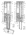
- the sampler E is mounted in a nozzle B of a fermenter Fe via a tip E1. It will be noted that the tapping B is directed obliquely upwards, relative to the wall of the fermenter, this inclination being intended to return the condensate towards the interior of the fermenter.
- the sampler consists of a frame E in which there has been arranged an upper chamber C1 and a lower chamber C2 extending by the nozzle E1.
- a piston 1 In the lower chamber C2, called the sampling chamber, is housed a piston 1 having in its end zone opposite the end piece E1 a shoulder 1 a .
- the piston At its other end, the piston is shaped so as to define a toroidal recess 1 b .
- Sealing means constituted by O-rings 1 c are provided on each side of the O-chamber 1 b .
- sealing means are also provided in the vicinity of the region of the shoulder 1 a, these sealing means are also constituted by O-rings 1 d.
- the dilution chamber C1 is provided with air intake orifices, 5, 6, according to the arrows f 1 , f 2 , with a steam intake orifice 7 according to the arrow f 3 and with an orifice. of dilution solvent 8.
- the C2 or sampling chamber is provided with two air intake-outlet orifices 9, 10, according to the arrows f 3 , f 4 , f 5 , f 6 , respectively.
- Chamber C2 is also provided with a purge orifice 11 according to arrow f 7 .
- the chambers C1 and C2 are joined by a passage or orifice 12.
- the sampler operates with a source of air com award winning S supplying by a series of valves V1, V2, V3, V5 the respective orifices 10, 9, 6, 5 by the respective conduits D1, D2, D3, D5.
- Compressed air is also admitted, on the one hand, through valve V4 and line C4 to a container R containing an appropriate solvent, for example water, a container in which the water subjected to the pressure of compressed air passes through the conduit D8 to the solvent intake port 8, and on the other hand, through the valve V6 and the conduit D6 to a filter Fi where the air being freed of its microorganisms and impurities is transferred to a mixing chamber Ch where this purified air is mixed with steam, the admission of which is controlled by a valve V7 via a conduit D7.
- the air-compressed / steam mixture is then brought by a duct D9 to the steam inlet orifice 8.
- valves V1 to V7 are advantageously solenoid valves controlled by a cam automaton Ac, itself actuated by a geared motor Mo and associated with pressure regulators M1 to M7. Downstream of the pressure regulators M1, M2, M3, lubricators L1, L2, L3 can be provided, this measurement is not however compulsory because the sampler according to the invention can also function efficiently, without the aid of lubrication agent.
- the operating cycle of the sampler according to the present invention is as follows: - when the sampler E is installed on the fermenter F, as shown in Figure 1, its operation can be broken down into five main operations as shown respectively in Figures 2 to 6.
- the first operation consists, before using the sampler, to sterilize the components contaminated by the external environment, for this purpose, the valves V3, V5, V6 and V7 are open, the other valves being closed, so as to, on the one hand, bring the pistons 3 and 4 into abutment against the stop 2, under the effect of the air admitted according to f1 and f2, in the chamber C1 while the mixture of filtered air coming from the filter f 1 and the steam are mixed in the chamber Ch before being admitted into the interior of the sampler through the intake orifice 8.
- the air / steam purge mixture then exits through the orifice 11 according to the arrow f 7 .
- the second operation consists in taking the sample.
- the valves V3 and V5 remain in the open state, while the valve V1 is opened so as to bring the sampling chamber 1b of the piston 1 inside the fermenter.
- the other valves V2, V4, V6 and V7 remain in the closed state.
- the third operation consists in bringing the sample back inside the sampler, and this, by closing the valve V1 and by opening the valve V2, the valves V3 and V5 always remaining closed, as well as the other valves.
- the air admitted according to f 5 through the orifice 9 acts on the shoulder 1a of the piston 1, to bring the latter into abutment against the wall of the chamber C1; this air flowing along f 6 through the orifice 10.
- the fourth operation represented by FIG. 5 consists in preparing a volume of solvent, for example water, intended for the dilution of the sample already taken according to the preceding operations.
- solvent for example water
- all the valves of the device are in the closed state, with the exception of valve V4 and valve V5.
- the compressed air pressure coming from the latter brings the piston 3 abutting against the stop 2, while the air pressure coming from the valve V4, causes, as described above, an inlet of solvent, for example from the water inside the chamber C2 through the inlet orifice 8.
- the opposite faces of the pistons 3 and 4 define with the internal faces of the chamber C1 a dilution volume becoming maximum when the piston 4 abuts against the stopper 14 of the bottom wall of said chamber C1.
- the fifth so-called “dilution-rinsing" operation consists in driving the duly diluted sample towards the analyzer, by opening the valve V3 which pushes the piston 4 abutting against the stop 2, while the piston 3 comes abutting against the opposite wall of the chamber C1, thus freeing the passage 12 between the chambers C1 and C2 in which the dilution-solvent liquid flows, which combining in the toric chamber 1 b flows towards the analyzer , not shown in the drawings, by the discharge or drain 11.
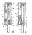
- the sterile sampler device consists of two bodies 101 and 102 connected together by screws.
- the body 101 acts as a tip and is fixed on the fermenter.
- a sealing plate 103 At the free end of the body 102 is provided a sealing plate 103.
- the assembly of the three elements 101, 102, 103 determines two cylindrical chambers, namely an upper or sampling chamber C3 and a lower chamber or dilution C4 .
- a sampling piston 104 capable of coming into abutment against an end plug 105 which seals the chamber C3.
- a piston called condensate 106 Inside the chamber C4 are mounted respectively three wandering pistons, namely a piston called condensate 106, a piston called steam 107 and a piston called diluent 108, the latter piston being liable to abut against a plug end 109 intended to seal the chamber C4.
- the piston 104 is in abutment on the right against the sealing plug 105.
- the piston 106 is pushed in abutment, on the left of the chamber C4, thus freeing the passage through the bores 110, 111.
- the piston 107 is pushed into abutment to the right of the zone 101 a of the chamber C3, on the shoulder of the chamber C3 thus freeing the passage through the bores 112, 113, while the piston 108 comes in abutment against the piston 107.
- the pressure at 114 is released before the end of the sterilization by atmospheric pressure to avoid that a slight leak in the seal of the C3 sampling chamber does not recontaminate the latter when the steam stops.
- the bores 116, 117 and 118 are at atmospheric pressure, while the solenoid valves associated with the bores 119 and 120 are closed. Steam is admitted through the orifice 120, it rises along the body of the piston 107, crosses the bore 112 then the sampling chamber of the piston 104 and is eliminated, as well as the condensates, according to the natural slope of sampling by the bore 110, then along the body of the piston 106 by the bore 111. After blowing the pressurization of the chamber for its rise in temperature is obtained by sequencing on a solenoid valve connected to the bore 111.
- the diameters of the bores and piston bodies are designed to allow easy passage of steam.
- the correct positioning of the piston 104 is ensured by the excitation of a stop sensor, not shown in the drawings, against the sealing plug 105.
- a stop sensor not shown in the drawings
- one proceeds, before the end of sterilization, to the filling of the water chamber of the sampling chamber C3 by an admission through the bore 120, considering that the bore 117 remains at atmospheric pressure from the sequence shown in Figure 7.
- the piston 108 then abuts against the sealing plug 109, while the piston 107 is not moved since it is maintained by the pressure of compressed air from the bore wise 114.
- a third operating sequence when the chamber sterilization time has elapsed, the system switches to the "sampling" position.
- the solenoid valve capable of occupying three positions, namely: admission of compressed air, bleeding, stopping, compressed air is admitted by bore 118
- the piston 104 releases the bore 112 which allows the vapor / air mixture to be filled with the chamber of the rod of the piston 104 (without evacuation) then releases the bore 110 which allows the establishment of a steam circuit through bores 122, 112, 110, 111 which sterilize the piston rod 104 as well as the chamber where it moves.
- the piston 104 therefore moves to the right.
- the control valve of the orifice 114 is brought to atmospheric pressure and l compressed air is sent through the orifice 116, causing the piston 106 to move to the right until it comes to a stop, as is more particularly shown in FIG. 11A.
- Bores 110 and 119 then communicate, the pressure 119 being atmospheric pressure.
- the piston 104 can then continue its course on the right until it comes into abutment with the sealing plug 105, as is more particularly shown in FIG. 11B.
- the residual pressure in the annular space of the piston 106 begins to expel the liquid along the path passing through the bores 112, 110, 119.
- the piston 104 should pause when the sampling chamber comes into communication with the orifice 110, this pause being used to move the piston 106 so as to avoid seeing the piston 104 reach its right position in abutment against the plug 105 while the piston 106 is always on the left and the piston 107 always on the right.
- a possible pressure imbalance between the respective annular spaces of the pistons 106 and 107 could then cause the liquid to flow back from the sampling chamber through the orifice 112 towards the bore 122.
- the sampler according to the present invention allows the control of the non-contamination of a culture medium by carrying out actual use cycles for several days. According to a preferred embodiment, it is possible, for example, to operate on a 20-liter fermenter, placed under normal culture conditions, with the notable exception of any intervention which may induce contamination and, of course, without innoculation. After normal fermentation, it will be possible, using the sampler according to the invention, to supply an analyzer, for example a device using the principle of enzyme electrodes, for rapidly carrying out assays of organic molecules in liquid medium. Any device, which by its design requires that it be supplied with samples of constant volume, is made particularly efficient thanks to its association with the sampler according to the present invention.
Landscapes
- Life Sciences & Earth Sciences (AREA)
- Health & Medical Sciences (AREA)
- Chemical & Material Sciences (AREA)
- Wood Science & Technology (AREA)
- Engineering & Computer Science (AREA)
- Organic Chemistry (AREA)
- Zoology (AREA)
- Bioinformatics & Cheminformatics (AREA)
- Biochemistry (AREA)
- General Health & Medical Sciences (AREA)
- Biomedical Technology (AREA)
- Sustainable Development (AREA)
- Genetics & Genomics (AREA)
- General Engineering & Computer Science (AREA)
- Molecular Biology (AREA)
- Biotechnology (AREA)
- Microbiology (AREA)
- General Physics & Mathematics (AREA)
- Hydrology & Water Resources (AREA)
- Physics & Mathematics (AREA)
- Immunology (AREA)
- Pathology (AREA)
- Analytical Chemistry (AREA)
- Apparatus Associated With Microorganisms And Enzymes (AREA)
- Measurement Of Radiation (AREA)
- Investigating Or Analysing Biological Materials (AREA)
- Measurement Of The Respiration, Hearing Ability, Form, And Blood Characteristics Of Living Organisms (AREA)
Priority Applications (1)
| Application Number | Priority Date | Filing Date | Title |
|---|---|---|---|
| AT87401150T ATE57768T1 (de) | 1986-05-22 | 1987-05-21 | Vorrichtung zur erhaltung der sterilitaet eines kulturmediums in einem behaelter waehrend der probenentnahme. |
Applications Claiming Priority (2)
| Application Number | Priority Date | Filing Date | Title |
|---|---|---|---|
| FR8607329A FR2599148B1 (fr) | 1986-05-22 | 1986-05-22 | Dispositif permettant de conserver la sterilite d'un milieu de culture en enceinte pendant le prelevement d'echantillons |
| FR8607329 | 1986-05-22 |
Publications (2)
| Publication Number | Publication Date |
|---|---|
| EP0246979A1 true EP0246979A1 (de) | 1987-11-25 |
| EP0246979B1 EP0246979B1 (de) | 1990-10-24 |
Family
ID=9335503
Family Applications (1)
| Application Number | Title | Priority Date | Filing Date |
|---|---|---|---|
| EP87401150A Expired - Lifetime EP0246979B1 (de) | 1986-05-22 | 1987-05-21 | Vorrichtung zur Erhaltung der Sterilität eines Kulturmediums in einem Behälter während der Probenentnahme |
Country Status (7)
| Country | Link |
|---|---|
| US (1) | US4957706A (de) |
| EP (1) | EP0246979B1 (de) |
| AT (1) | ATE57768T1 (de) |
| DE (1) | DE3765694D1 (de) |
| ES (1) | ES2018032B3 (de) |
| FR (1) | FR2599148B1 (de) |
| GR (1) | GR3001139T3 (de) |
Families Citing this family (12)
| Publication number | Priority date | Publication date | Assignee | Title |
|---|---|---|---|---|
| FR2652897B1 (fr) * | 1989-10-10 | 1994-01-07 | Institut Francais Petrole | Dispositif et procede pour transferer un echantillon de fluide entre deux chambres et application notamment a la chromatographie gazeuse. |
| US5384095A (en) * | 1990-08-08 | 1995-01-24 | ANDOS Technik fur die Medizin GmbH | Apparatus for the transfer of a defined specimen quantity from an outer space into a test chamber |
| US5150601A (en) * | 1990-12-21 | 1992-09-29 | The Dow Chemical Company | Fluid sampling for gas chromatograph with modified sampling valve |
| CA2088682A1 (en) * | 1991-06-18 | 1992-12-19 | Nicolae Paraschiv | Demountable, replaceable aspirating needle cartridge assembly |
| FR2704757B1 (fr) * | 1993-05-07 | 1995-08-11 | Framatome Sa | Dispositif de stérilisation à haute pression de produits. |
| US5730938A (en) * | 1995-08-09 | 1998-03-24 | Bio-Chem Laboratory Systems, Inc. | Chemistry analyzer |
| US6258324B1 (en) | 1999-03-15 | 2001-07-10 | Felix H. Yiu | Pipette dispensing block |
| WO2003061453A2 (en) * | 2001-12-04 | 2003-07-31 | Lifepoint, Inc. | Device and method for the identification of analytes in bodily fluids |
| US7549349B2 (en) * | 2006-06-22 | 2009-06-23 | Evogen, Inc. | Sample cartridge for air-sampling device |
| US8365617B2 (en) * | 2010-06-25 | 2013-02-05 | Mettler-Toledo Ag | Sampling device |
| US8312780B2 (en) * | 2010-06-25 | 2012-11-20 | Mettler-Toledo Ag | Sampling device and method |
| US9410871B1 (en) * | 2012-10-22 | 2016-08-09 | A+ Manufacturing, Llc | Apparatus for analytical sampling and/or conditioning of a process gas with selective isolation capability, and method therefore |
Citations (4)
| Publication number | Priority date | Publication date | Assignee | Title |
|---|---|---|---|---|
| US3746217A (en) * | 1971-09-07 | 1973-07-17 | E Hanset | Measuring system |
| FR2250109A1 (de) * | 1973-11-05 | 1975-05-30 | Commissariat Energie Atomique | |
| FR2524144A1 (fr) * | 1982-03-24 | 1983-09-30 | Inst Rech Hydrologiques | Preleveur d'echantillons |
| DE3338782A1 (de) * | 1983-10-26 | 1985-05-15 | Sartorius GmbH, 3400 Göttingen | Vorrichtung zur aseptischen probeentnahme von fluessigkeiten aus einer leitung, insbesondere in der getraenke-, pharma- und kosmetikindustrie |
Family Cites Families (3)
| Publication number | Priority date | Publication date | Assignee | Title |
|---|---|---|---|---|
| US4585623A (en) * | 1984-02-27 | 1986-04-29 | Allelix Inc. | Device for performing quantitative chemical and immunochemical assays |
| US4649028A (en) * | 1985-03-27 | 1987-03-10 | Medica Corporation | Electrolyte analyzer |
| US4640821A (en) * | 1985-07-16 | 1987-02-03 | Fisher Scientific Company | Analysis apparatus |
-
1986
- 1986-05-22 FR FR8607329A patent/FR2599148B1/fr not_active Expired
-
1987
- 1987-05-21 DE DE8787401150T patent/DE3765694D1/de not_active Expired - Lifetime
- 1987-05-21 US US07/052,409 patent/US4957706A/en not_active Expired - Fee Related
- 1987-05-21 EP EP87401150A patent/EP0246979B1/de not_active Expired - Lifetime
- 1987-05-21 ES ES87401150T patent/ES2018032B3/es not_active Expired - Lifetime
- 1987-05-21 AT AT87401150T patent/ATE57768T1/de not_active IP Right Cessation
-
1990
- 1990-11-30 GR GR90401003T patent/GR3001139T3/el unknown
Patent Citations (4)
| Publication number | Priority date | Publication date | Assignee | Title |
|---|---|---|---|---|
| US3746217A (en) * | 1971-09-07 | 1973-07-17 | E Hanset | Measuring system |
| FR2250109A1 (de) * | 1973-11-05 | 1975-05-30 | Commissariat Energie Atomique | |
| FR2524144A1 (fr) * | 1982-03-24 | 1983-09-30 | Inst Rech Hydrologiques | Preleveur d'echantillons |
| DE3338782A1 (de) * | 1983-10-26 | 1985-05-15 | Sartorius GmbH, 3400 Göttingen | Vorrichtung zur aseptischen probeentnahme von fluessigkeiten aus einer leitung, insbesondere in der getraenke-, pharma- und kosmetikindustrie |
Also Published As
| Publication number | Publication date |
|---|---|
| DE3765694D1 (de) | 1990-11-29 |
| EP0246979B1 (de) | 1990-10-24 |
| FR2599148B1 (fr) | 1988-09-16 |
| GR3001139T3 (en) | 1992-06-25 |
| ES2018032B3 (es) | 1991-03-16 |
| US4957706A (en) | 1990-09-18 |
| ATE57768T1 (de) | 1990-11-15 |
| FR2599148A1 (fr) | 1987-11-27 |
Similar Documents
| Publication | Publication Date | Title |
|---|---|---|
| EP0246979B1 (de) | Vorrichtung zur Erhaltung der Sterilität eines Kulturmediums in einem Behälter während der Probenentnahme | |
| US5911881A (en) | Apparatus and method for collecting analyte in supercritical fluid extraction | |
| US5268102A (en) | Apparatus and method for supercritical fluid extraction | |
| EP0094319A1 (de) | Rotationsrheometer zum Durchführen von Messungen unter hohen Temperatur- und Druckverhältnissen mit Probennahmevorrichtung | |
| JP2007519007A5 (de) | ||
| JP3435457B2 (ja) | ガスクロマトグラフィ分析に試料を適用する方法とこれに用いるサンプルチューブ | |
| US4873876A (en) | Chemical process sampler | |
| JPH11211630A (ja) | ガス試料捕集装置及びその使用方法 | |
| JPH10507270A (ja) | 流体サンプリング装置 | |
| JP3377838B2 (ja) | 超臨界流体抽出装置 | |
| FR2652426A1 (fr) | Detendeur de bouteille de gaz. | |
| EP0510355A1 (de) | Vorrichtung zur keimfreien Probenentnahme eines Produktes | |
| EP0033709A1 (de) | Selbständiges Gerät zur isobarometrischen Probenahme von kohlensäurehaltigen Getränken | |
| EP0910787B1 (de) | Verfahren und vorrichtung zum füllen einer testkard mit flüssigkeiten | |
| US8904886B1 (en) | Devices for obtaining cylinder samples of natural gas or process gas and methods therefore | |
| JP3373243B2 (ja) | 臨界超過流体抽出装置 | |
| RU2249693C1 (ru) | Контейнер-пробоотборник | |
| CN100401060C (zh) | 在色谱分离法中预先浓缩被分析物的连接组件 | |
| FR2655145A1 (en) | Bottle for transporting a fluid sample, in particular of hydrocarbon | |
| RU2794235C1 (ru) | Устройство для анализа с дополнительным концентрированием состава равновесной паровой фазы | |
| EP1634002B1 (de) | Füll- und leerventil und reinigungsgerät für einen flüssigkeitsdruckbehälter | |
| FR2621390A1 (fr) | Dispositif de transfert d'une quantite determinee de fluide entre une conduite et une derivation | |
| WO2004081540A3 (en) | Device for automatic and programmed sampling and dosingof liquid mediums | |
| NO300397B1 (no) | Anordning ved prövetakingsflaske | |
| FR2921489A1 (fr) | Echantillonnage et stockage de produit en continu, sous pression constante et volume variable |
Legal Events
| Date | Code | Title | Description |
|---|---|---|---|
| PUAI | Public reference made under article 153(3) epc to a published international application that has entered the european phase |
Free format text: ORIGINAL CODE: 0009012 |
|
| AK | Designated contracting states |
Kind code of ref document: A1 Designated state(s): AT BE CH DE ES FR GB GR IT LI LU NL SE |
|
| 17P | Request for examination filed |
Effective date: 19880211 |
|
| 17Q | First examination report despatched |
Effective date: 19900126 |
|
| GRAA | (expected) grant |
Free format text: ORIGINAL CODE: 0009210 |
|
| AK | Designated contracting states |
Kind code of ref document: B1 Designated state(s): AT BE CH DE ES FR GB GR IT LI LU NL SE |
|
| PG25 | Lapsed in a contracting state [announced via postgrant information from national office to epo] |
Ref country code: IT Free format text: LAPSE BECAUSE OF FAILURE TO SUBMIT A TRANSLATION OF THE DESCRIPTION OR TO PAY THE FEE WITHIN THE PRE;WARNING: LAPSES OF ITALIAN PATENTS WITH EFFECTIVE DATE BEFORE 2007 MAY HAVE OCCURRED AT ANY TIME BEFORE 2007. THE CORRECT EFFECTIVE DATE MAY BE DIFFERENT FROM THE ONE RECORDED.SCRIBED TIME-LIMIT Effective date: 19901024 |
|
| REF | Corresponds to: |
Ref document number: 57768 Country of ref document: AT Date of ref document: 19901115 Kind code of ref document: T |
|
| GBT | Gb: translation of ep patent filed (gb section 77(6)(a)/1977) | ||
| REF | Corresponds to: |
Ref document number: 3765694 Country of ref document: DE Date of ref document: 19901129 |
|
| PGFP | Annual fee paid to national office [announced via postgrant information from national office to epo] |
Ref country code: FR Payment date: 19910405 Year of fee payment: 5 |
|
| PGFP | Annual fee paid to national office [announced via postgrant information from national office to epo] |
Ref country code: LU Payment date: 19910410 Year of fee payment: 5 |
|
| PGFP | Annual fee paid to national office [announced via postgrant information from national office to epo] |
Ref country code: AT Payment date: 19910423 Year of fee payment: 5 Ref country code: ES Payment date: 19910423 Year of fee payment: 5 |
|
| PGFP | Annual fee paid to national office [announced via postgrant information from national office to epo] |
Ref country code: GR Payment date: 19910425 Year of fee payment: 5 |
|
| PGFP | Annual fee paid to national office [announced via postgrant information from national office to epo] |
Ref country code: GB Payment date: 19910513 Year of fee payment: 5 |
|
| PGFP | Annual fee paid to national office [announced via postgrant information from national office to epo] |
Ref country code: BE Payment date: 19910514 Year of fee payment: 5 |
|
| PGFP | Annual fee paid to national office [announced via postgrant information from national office to epo] |
Ref country code: SE Payment date: 19910517 Year of fee payment: 5 |
|
| ITTA | It: last paid annual fee | ||
| PGFP | Annual fee paid to national office [announced via postgrant information from national office to epo] |
Ref country code: CH Payment date: 19910531 Year of fee payment: 5 Ref country code: NL Payment date: 19910531 Year of fee payment: 5 |
|
| PGFP | Annual fee paid to national office [announced via postgrant information from national office to epo] |
Ref country code: DE Payment date: 19910618 Year of fee payment: 5 |
|
| REG | Reference to a national code |
Ref country code: GR Ref legal event code: FG4A Free format text: 3001139 |
|
| PLBE | No opposition filed within time limit |
Free format text: ORIGINAL CODE: 0009261 |
|
| STAA | Information on the status of an ep patent application or granted ep patent |
Free format text: STATUS: NO OPPOSITION FILED WITHIN TIME LIMIT |
|
| EPTA | Lu: last paid annual fee | ||
| 26N | No opposition filed | ||
| PG25 | Lapsed in a contracting state [announced via postgrant information from national office to epo] |
Ref country code: LU Free format text: LAPSE BECAUSE OF NON-PAYMENT OF DUE FEES Effective date: 19920521 Ref country code: AT Effective date: 19920521 Ref country code: GB Effective date: 19920521 |
|
| PG25 | Lapsed in a contracting state [announced via postgrant information from national office to epo] |
Ref country code: ES Free format text: LAPSE BECAUSE OF NON-PAYMENT OF DUE FEES Effective date: 19920522 Ref country code: SE Effective date: 19920522 |
|
| PG25 | Lapsed in a contracting state [announced via postgrant information from national office to epo] |
Ref country code: LI Effective date: 19920531 Ref country code: BE Effective date: 19920531 Ref country code: CH Effective date: 19920531 |
|
| BERE | Be: lapsed |
Owner name: CENTRE NATIONAL DE LA RECHERCHE SCIENTIFIQUE CNRS Effective date: 19920531 |
|
| PG25 | Lapsed in a contracting state [announced via postgrant information from national office to epo] |
Ref country code: GR Free format text: THE PATENT HAS BEEN ANNULLED BY A DECISION OF A NATIONAL AUTHORITY Effective date: 19921130 |
|
| PG25 | Lapsed in a contracting state [announced via postgrant information from national office to epo] |
Ref country code: NL Effective date: 19921201 |
|
| NLV4 | Nl: lapsed or anulled due to non-payment of the annual fee | ||
| GBPC | Gb: european patent ceased through non-payment of renewal fee |
Effective date: 19920521 |
|
| PG25 | Lapsed in a contracting state [announced via postgrant information from national office to epo] |
Ref country code: FR Effective date: 19930129 |
|
| REG | Reference to a national code |
Ref country code: CH Ref legal event code: PL |
|
| PG25 | Lapsed in a contracting state [announced via postgrant information from national office to epo] |
Ref country code: DE Effective date: 19930202 |
|
| REG | Reference to a national code |
Ref country code: FR Ref legal event code: ST |
|
| REG | Reference to a national code |
Ref country code: GR Ref legal event code: MM2A Free format text: 3001139 |
|
| EUG | Se: european patent has lapsed |
Ref document number: 87401150.5 Effective date: 19921204 |
|
| REG | Reference to a national code |
Ref country code: ES Ref legal event code: FD2A Effective date: 19990201 |