EP0246801B1 - Optisches System zur Bilderzeugung - Google Patents
Optisches System zur Bilderzeugung Download PDFInfo
- Publication number
- EP0246801B1 EP0246801B1 EP87304224A EP87304224A EP0246801B1 EP 0246801 B1 EP0246801 B1 EP 0246801B1 EP 87304224 A EP87304224 A EP 87304224A EP 87304224 A EP87304224 A EP 87304224A EP 0246801 B1 EP0246801 B1 EP 0246801B1
- Authority
- EP
- European Patent Office
- Prior art keywords
- scanning
- mask
- imaging element
- mirror
- receiving
- Prior art date
- Legal status (The legal status is an assumption and is not a legal conclusion. Google has not performed a legal analysis and makes no representation as to the accuracy of the status listed.)
- Expired - Lifetime
Links
Images


Classifications
-
- G—PHYSICS
- G06—COMPUTING OR CALCULATING; COUNTING
- G06K—GRAPHICAL DATA READING; PRESENTATION OF DATA; RECORD CARRIERS; HANDLING RECORD CARRIERS
- G06K15/00—Arrangements for producing a permanent visual presentation of the output data, e.g. computer output printers
- G06K15/02—Arrangements for producing a permanent visual presentation of the output data, e.g. computer output printers using printers
- G06K15/12—Arrangements for producing a permanent visual presentation of the output data, e.g. computer output printers using printers by photographic printing, e.g. by laser printers
- G06K15/1238—Arrangements for producing a permanent visual presentation of the output data, e.g. computer output printers using printers by photographic printing, e.g. by laser printers simultaneously exposing more than one point
-
- B—PERFORMING OPERATIONS; TRANSPORTING
- B23—MACHINE TOOLS; METAL-WORKING NOT OTHERWISE PROVIDED FOR
- B23K—SOLDERING OR UNSOLDERING; WELDING; CLADDING OR PLATING BY SOLDERING OR WELDING; CUTTING BY APPLYING HEAT LOCALLY, e.g. FLAME CUTTING; WORKING BY LASER BEAM
- B23K26/00—Working by laser beam, e.g. welding, cutting or boring
- B23K26/02—Positioning or observing the workpiece, e.g. with respect to the point of impact; Aligning, aiming or focusing the laser beam
- B23K26/06—Shaping the laser beam, e.g. by masks or multi-focusing
- B23K26/064—Shaping the laser beam, e.g. by masks or multi-focusing by means of optical elements, e.g. lenses, mirrors or prisms
- B23K26/066—Shaping the laser beam, e.g. by masks or multi-focusing by means of optical elements, e.g. lenses, mirrors or prisms by using masks
-
- B—PERFORMING OPERATIONS; TRANSPORTING
- B41—PRINTING; LINING MACHINES; TYPEWRITERS; STAMPS
- B41B—MACHINES OR ACCESSORIES FOR MAKING, SETTING, OR DISTRIBUTING TYPE; TYPE; PHOTOGRAPHIC OR PHOTOELECTRIC COMPOSING DEVICES
- B41B17/00—Photographic composing machines having fixed or movable character carriers and without means for composing lines prior to photography
- B41B17/18—Details
- B41B17/20—Character carriers; Cleaning devices therefor
- B41B17/24—Character carriers; Cleaning devices therefor with all characters
- B41B17/30—Character carriers; Cleaning devices therefor with all characters on a sheet of square or rectangular shape
-
- B—PERFORMING OPERATIONS; TRANSPORTING
- B41—PRINTING; LINING MACHINES; TYPEWRITERS; STAMPS
- B41B—MACHINES OR ACCESSORIES FOR MAKING, SETTING, OR DISTRIBUTING TYPE; TYPE; PHOTOGRAPHIC OR PHOTOELECTRIC COMPOSING DEVICES
- B41B17/00—Photographic composing machines having fixed or movable character carriers and without means for composing lines prior to photography
- B41B17/18—Details
- B41B17/20—Character carriers; Cleaning devices therefor
- B41B17/24—Character carriers; Cleaning devices therefor with all characters
- B41B17/32—Character carriers; Cleaning devices therefor with all characters on a flat disc
-
- B—PERFORMING OPERATIONS; TRANSPORTING
- B41—PRINTING; LINING MACHINES; TYPEWRITERS; STAMPS
- B41B—MACHINES OR ACCESSORIES FOR MAKING, SETTING, OR DISTRIBUTING TYPE; TYPE; PHOTOGRAPHIC OR PHOTOELECTRIC COMPOSING DEVICES
- B41B21/00—Common details of photographic composing machines of the kinds covered in groups B41B17/00 and B41B19/00
- B41B21/16—Optical systems
- B41B21/18—Optical systems defining a single optical path
- B41B21/20—Optical systems defining a single optical path with means for moving stepwise
-
- G—PHYSICS
- G02—OPTICS
- G02B—OPTICAL ELEMENTS, SYSTEMS OR APPARATUS
- G02B26/00—Optical devices or arrangements for the control of light using movable or deformable optical elements
- G02B26/08—Optical devices or arrangements for the control of light using movable or deformable optical elements for controlling the direction of light
- G02B26/10—Scanning systems
-
- B—PERFORMING OPERATIONS; TRANSPORTING
- B23—MACHINE TOOLS; METAL-WORKING NOT OTHERWISE PROVIDED FOR
- B23K—SOLDERING OR UNSOLDERING; WELDING; CLADDING OR PLATING BY SOLDERING OR WELDING; CUTTING BY APPLYING HEAT LOCALLY, e.g. FLAME CUTTING; WORKING BY LASER BEAM
- B23K2101/00—Articles made by soldering, welding or cutting
- B23K2101/007—Marks, e.g. trade marks
Definitions
- the present invention relates to a character imaging system, the term "character” being used herein to refer to a letter of the alphabet, a numeral or other symbol.
- the invention is concerned with a system in which a selected one of a plurality of different such characters arrayed as windows in an otherwise opaque mask is projected optically onto a selected location on a working surface.
- One important application for the present invention is in a system for marking a workpiece by means of laser light.
- the term "light” as used throughout this specification and claims is intended to cover not only visible light, but also infra-red and ultra violet light.
- High energy, pulsed (or continuous wave) coherent light is projected sequentially through selected character-defining windows in a mask to burn an impression of such characters into a workpiece.
- the workpiece is moved, or the beam is deflected by movement of the optical system, so that a word or sentence is written on the workpiece.
- Another application of the present invention resides in the formation of words or messages that are projected onto a surface such as photographic film, or a screen, or, on a larger scale, onto a wall, or even the side of a building, e.g. to provide a visual display.
- the light need not be coherent light.
- These latter applications of the invention nevertheless maintain the basic feature that the displayed message is generated by projecting a beam sequentially through different selected windows in a mask to spell out the message.
- a principal object of the present invention is to provide a character imaging system that is capable of achieving improved performance without a need to move any one of the three important elements mentioned above, namely the mask, the final lens, or the working surface, although in some of its embodiments the invention does not preclude movement of one or more of these elements in circumstances in which a further special advantage can be achieved thereby.
- a character imaging system comprising:
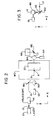
- the system provides a light source in the form of a laser 10.
- a beam 12 from the laser 10 enters a telescope 14 where it is reduced in width.
- a typical TEA CO2 pulsed laser would provide a beam of square cross-section with a width of about 1 inch in each direction.
- the telescope 14 will reduce this beam to a square beam with sides each about half an inch in width.
- the thus narrowed beam 16 is directed in a direction X onto the surface of a flat circular mirror M1 that is controlled by a galvanometer G1 to rotate about an axis extending in a direction Z perpendicular to the direction X.
- the mirror M1 reflects the beam 16 onto a second similar mirror M2 that is controlled by a further galvanometer G2 to rotate about an axis extending in the X direction.
- the mirrors M1 and M2 form a first or "transmitting" assembly, the scanning function of which will be more fully described below.
- a parallel light beam 17 is projected by this transmitting assembly, generally in the direction Z, and onto the surface of a fixed, spherically concave mirror M3.
- the mirror M3 constitutes a "first imaging element” and serves to reflect a converging, focused beam 18 towards a second or “receiving” assembly that consists of further flat mirrors M4 and M5.
- the mirror M4 which directly receives the focused beam from the spherical mirror M3 is controlled by a galvanometer G4 to rotate about an axis in a direction Y (perpendicular to both the directions X and Z), and reflects the beam onto the mirror M5. which is controlled by a galvanometer G5 to rotate about an axis extending in the direction Z.
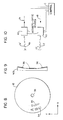
- the beam 18 passes through a fixed mask 20 (see Figure 5) to form a modified focused beam 19, i.e. a beam that has been modified by having passed through a window in the mask and hence having adopted the shape of one of the character-defining windows.
- the mask 20 is generally opaque, except for rows and columns of windows, each in the shape of a character 22, e.g. letters A, B, C etc.
- the geometry of the system is such, including the mask 20 being offset from the principal axis A of the mirror M3 (as best seen in Figures 1 and 2), that the transmitted beam 17 misses the mask, while the return beam 18 must pass through it to become the modified beam 19.
- the axis A extends in the direction Z and intersects a line B joining the centre points of the mirrors M2 and M4, i.e. the mirrors that respectively directly transmit the beam 16 to the mirror M3 and directly receive the beam 19 from the mirror M3.
- These axes A and B define a plane that extends in the X and Z directions.
- the axis B is spaced along the axis A from the mirror M3 by a distance 2f, where f is the focal length of the mirror M3.
- the mask 20 is preferably spaced from the mirror M3 by a distance slightly less than the focal length f, e.g. by a distance approximately equal to 0.8f.
- the mask need not necessarily be located in the reflected beam 18. Instead it can be located in the transmitted beam 17.
- the transmitted beam need not necessarily be a parallel beam. It could be a converging or diverging beam, in which case the beam reflected by the concave mirror M3 could be converging, diverging or parallel.
- the beam 19, now conveniently referred to as a working beam 21 passes to a fixed flat mirror M6 and then through a final lens L1 onto a workpiece W.
- the lens L1 constitutes a "second imaging element.”
- the lens L1 will preferably be a compound, flat field lens, i.e. one that will ensure that the image of the chosen mask character will be correctly focused on any selected area of the workpiece surface. Should the workpiece surface be appropriately concave, a normal lens could be used.
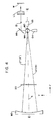
- the function of the movable mirror M1 of the transmitting assembly is to scan the beam 17 in the X direction, e.g. between paths 17 and 17 ⁇ shown in Figure 1.
- the mirror M3 ensures that the reflected beam 19 or 19 ⁇ (focused and modified to carry the character data) arrives at the mirror M4 regardless of whether the transmitted beam followed path 17 or 17 ⁇ , thus, in effect, regardless of which character in the mask was traversed by the beam.
- the mirror M4 of the receiving assembly is moved in synchronism with the mirror M1 of the transmitting assembly so as to seek the received beam 19 or 19 ⁇ and to ensure that it is always reflected as the working beam in the same path 21 extending towards the mirror M5, subject to a superimposed incremental advance that will be described below.
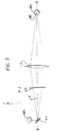
- the mirrors M2 and M5 synchronously scan and seek the transmitted and received beams in the Y direction. See Figure 4 where the transmitted and received beams are shown coincident, i.e. assuming no simultaneous X direction scanning, the beams being shown as scanned from 17 (transmitted) and 19 (received) to 17 ⁇ and 19 ⁇ , respectively. In practice, of course, scanning can take place in the X and Y directions simultaneously, if desired.
- the galvanometers G1, G2, G4 and G5 are controlled for this purpose by a control computer C, the receiving assembly always seeking the received beam in the correct direction having regard to its transmitted direction and the ultimate working beam path 21 that it is to follow. In this manner, the beam received by the workpiece can be caused to pass through any selected one of the characters in the mask, without any need to move the mask.
- the X scan mirrors come first in the direction of travel of the beam (i.e. mirrors M1 and M4) and the Y scan mirrors follow (mirrors M2 and M5) this sequence can be reversed provided it is done in both the transmitting and receiving assemblies.
- the fixed spherical mirror M3 serves the dual functions of condenser and imager.
- As the so-called first imaging element it images the transmitting assembly of mirrors M1, M2 onto the receiving assembly of mirrors M4, M5.
- the final lens L1 on the other hand, the so-called second imaging element, is spaced from the mask and the workpiece and has a focal length such as to ensure that it images the selected character in the mask 20 onto the workpiece W.
- a spherical shape for the mirror M3 is preferred, because it is the cheapest to manufacture, but other concave shapes, such as ellipsoidal, could also be used.
- the control C will superimpose on the above described movements of the mirror M4 (for X direction movement) and of the mirror M5 (for Y direction movement), i.e. those necessary to keep the path 21 extending in a fixed direction, further incremental movements that move the path 21 in the manner necessary to achieve the desired distribution of the characters on the workpiece surface.
- Calibration of the positions of the mirrors M1 and M2 of the transmitting assembly can be achieved by means of a plurality (preferably four) sensors 24 ( Figure 5) located at convenient places, e.g. the corners, of the mask 20.
- the galvanometers G1 and G2 will initially be programmed by the control C to scan until each one of these sensors 24 has been energised, thus serving to identify various orientations of the transmitted beam.
- a set of holes 26 is provided in the mask. As the beam passes through each such hole and is received and detected downstream, e.g. by a sensor (not shown) located at a datum point in the workpiece plane, the orientation of the working beam and hence of the mirrors M4 and M5 becomes known.
- a subsidiary laser or lamp 28 can be used, its beam 29 being fed into the system by a beam combining element 30, e.g. a germanium flat, as shown in Figure 6.
- the invention is not dependent on the use of coherent light as the source, although this will normally be necessary when marking a workpiece.
- the laser 10 can be replaced by a lamp.
- the mirror M3 can be replaced as the first imaging element by a lens L2, as shown in Figure 7, with the two mirror assemblies M1, M2, M4, M5 then located symmetrically and equidistantly on opposite sides of such lens, with the mask 20 preferably, but not necessarily, located downstream of the lens.
- the preferred distance for each of the mirrors M2 and M4 from the lens L2 will be 2f, where f is the focal length of the lens.
- This arrangement has the advantage that the mask can be centered on the principal axis A of the lens.
- a significant advantage of the mirror M3 is that it will usually result in a more compact mechanical configuration.
- One of the advantages of the present invention is that it enables effective scanning of a fixed mask to select a desired character and the positioning of an image of this character at a chosen location on a workpiece, or screen, or other surface.
- the term "work surface” is used in the claims that follow to refer generically to these various possibilities.
- Figure 8 shows a mask in the form of a disc 32 rotatable about an axis 33 and carrying two (or more) peripheral series 34, 35 of characters. Selection of a desired character is achieved by spinning the disc 32 and energising the laser when the selected character is in line with the beam. Increased speed of operation can be achieved by increasing the speed of rotation of the disc 32, or by repeating the alphabet (or other sequence of characters) around the disc.
- Figure 9 shows a further simplification that is especially appropriate for use with embodiments of the invention described in connection with Figure 8, namely the substitution of a series of flat mirror surfaces 36 arranged in an approximately spherical array to furnish a mirror M3 ⁇ that can be used to replace the mirror M3 as the first imaging element.
- This concave array of flat mirror surfaces can be used instead of a true concave surface, is that in the Figure 8 embodiment there will be a relative small number of accessed character positions through which the beam must be scanned.
- Figure 10 shows an alternative device for use as either the transmitting assembly or the receiving assembly or both, namely an acousto-optical device 40 for scanning either beam in the X and Y directions.
Landscapes
- Physics & Mathematics (AREA)
- Optics & Photonics (AREA)
- Engineering & Computer Science (AREA)
- General Physics & Mathematics (AREA)
- General Engineering & Computer Science (AREA)
- Mechanical Engineering (AREA)
- Plasma & Fusion (AREA)
- Theoretical Computer Science (AREA)
- Mechanical Optical Scanning Systems (AREA)
- Laser Beam Processing (AREA)
- Laser Beam Printer (AREA)
- Dot-Matrix Printers And Others (AREA)
- Printers Or Recording Devices Using Electromagnetic And Radiation Means (AREA)
Claims (11)
- Optisches Zeichenabbildungssystem mit:a) einer Lichtquelle (10, 14);b) einer Abstrahlbaugruppe (M1, M2) zum Empfang eines von der Quelle ankommenden Lichtstrahles (16) und zur Projektion eines übertragenen Lichtstrahles (17);c) einer Empfangsbaugruppe (M4, M5);d) einem ersten Element (M3, L2) zum Empfang des von der Abstrahlbaugruppe abgestrahlten Strahles (17) und zum Richten des Strahles (18) auf die Empfangsbaugruppe;e) einer opaken Maske (20) im Weg des Strahles (18), wobei die Maske ein Feld von Fenstern (22) besitzt, von denen jedes die Form eines Zeichens hat, dessen Bild auf eine Arbeitsfläche (W) zu projizieren ist;f) Mitteln (G1, G2 oder G1, 33) zum Ablenken des abgestrahlten Strahles (17) und der Maske relativ zueinander in einer Richtung im wesentlichen rechtwinklig zur Richtung der Ausbreitung (Z) des abgestrahlten Strahles, wodurch der Strahl (18, 19) durch die Maske läuft, um durch ein ausgewähltes Zeichen in der Maske zu laufen;g) wobei die Empfangsbaugruppe außerdem Ablenkmittel (G4, G5) aufweist, die mit den Mitteln zum Ablenken des abgestrahlten Strahles synchronisiert werden, um den vom ersten Abbildungselement empfangenen Strahl (19) in zwei Richtungen (X, Y) rechtwinklig zueinander und jeweils im wesentlichen rechtwinklig zur Richtung der Ausbreitung (Z) des empfangenen Strahles (19) abzulenken, um einen Arbeitsstrahl zu bilden, der in einer Richtung läuft, diei) unabhängig davon ist, welches Zeichen in der Maske vom projizierten Strahl durchlaufen wird, undii) von einer gewünschten Stelle auf der Arbeitsfläche bestimmt wird, auf die ein Bild des durchlaufenen Zeichens in der Maske zu projizieren ist; undh) einem zweiten Abbildungselement (L1) zum Empfang des Arbeitsstrahles und zur Projizierung des Arbeitsstrahles auf die Arbeitsfläche (W);i) wobei der Abstand der Maske und der Arbeitsfläche vom zweiten Abbildungselement und die Brennweite des zweiten Abbildungselementes derart sind, daß ein Bild des durchlaufenen Zeichens auf die Arbeitsfläche projiziert wird,
dadurch gekennzeichnet, daßj) die Mittel (G1, G2 oder G1, 33) zur Ablenkung des abgestrahlten Strahles so angeordnet sind, daß der Strahl und die Maske relativ zueinander in zwei Richtungen (X, Y) rechtwinklig zueinander und jeweils im wesentlichen rechtwinklig zur Richtung der Ausbreitung (Z) des abgestrahlten Strahles (17) abgelenkt werden, wobei mindestens eine der Ablenkrichtungen durch ein in der Abstrahlbaugruppe (M1, M2) vorgesehenes Mittel (G1) erzeugt wird; undk) das erste Element (M3, L2) ein Abbildungselement ist, wobei der Abstand der Baugruppen (M1, M2; M4, M5) vom ersten Abbildungselement und die Brennweite des ersten Abbildungselementes derart sind, daß das erste Abbildungselement die Abstrahlbaugruppe auf die Empfangsbaugruppe unabhängig davon abbildet, welches Zeichen in der Maske vom Strahl durchlaufen wird. - System nach Anspruch 1, bei welchem die Mittel (G1, G2) zum Ablenken des abgestrahlten Strahles in der Abstrahlbaugruppe vorgesehen sind und die Maske stationär angeordnet ist.
- System nach Anspruch 1, bei welchem die Mittel zum Ablenken des abgestrahlten Strahles in der Abstrahlbaugruppe vorgesehene Mittel (G1) zur Ablenkung des abgestrahlten Strahles in die erste Richtung (X) und Mittel zum Bewegen der Maske in die zweite Richtung (Y) aufweisen.
- System nach Anspruch 2, bei welchem die Abstrahlbaugruppe(k) zwei flache Spiegel (M1, M2) aufweist, von denen ein erster den von der Quelle ankommenden Lichtstrahl empfängt und ein zweiter einen vom ersten Spiegel reflektierten Strahl empfängt und den abgestrahlten Strahl zum ersten Abbildungselement im wesentlichen in die Z-Richtung projiziert,und wobei die Ablenkmittel (G1, G2) der Abstrahlbaugruppe(l) ein Mittel (G1) zur Rotation eines der beiden flachen Spiegel zum Ablenken des abgestrahlten Strahles in die X-Richtung und(m) ein Mittel (G2) zur Rotation des anderen der beiden flachen Spiegel zur Ablenkung des abgestrahlten Strahles in der Y-Richtung aufweist.
- System nach Anspruch 4, bei welchem die Empfangsbaugruppe(n) ein zweites Paar von flachen Spiegeln (M4, M5) aufweist, von denen ein erster den Strahl vom ersten Abbildungselement empfängt und ein zweiter einen reflektierten Strahl vom ersten Spiegel des zweiten Paares empfängt und den Arbeitsstrahl projiziert,wobei die zusätzlichen Ablenkmittel (G4, G5) der Empfangsbaugruppe(o) ein Mittel (G4) zur Rotation des einen des zweiten Paares von Spiegeln zur Ablenkung des vom ersten Bilderzeugungselement empfangenen Strahles in die X-Richtung und(p) ein Mittel (G5) zur Rotation des anderen des zweiten Paares der Spiegel zur Ablenkung des vom ersten Bilderzeugungselement empfangenen Strahles in die Y-Richtung aufweist,und wobei das System(q) eine Steuereinrichtung (C) aufweist zur(i) Synchronisierung der Rotation des X-Richtungs-Ablenkpiegels der Abstrahlbaugruppe mit der des X-Richtungs-Ablenkspiegels der Empfangsbaugruppe und zur Synchronisierung der Rotation des Y-Richtungs-Ablenkspiegels der Abstrahlbaugruppe mit der des Y-Richtungs-Ablenkspiegels der Empfangsbaugruppe, um die Richtung der Ausbreitung des Arbeitsstrahles unabhängig von den vom Strahl gefolgten Wegen und somit unabhängig vom durchlaufenen Zeichen in der Maske zu machen, und(ii) zur zusätzlichen Rotation von mindestens einem der Spiegel der Empfangsbaugruppe, um die Richtung der Ausbreitung des Arbeitsstrahles für eine Projizierung des Arbeitsstrahles auf die gewünschte Stelle auf der Arbeitsfläche zu verändern.
- System nach einem der vorangegangenen Ansprüche, bei welchem mindestens eine der Abstrahl- und Empfangsbaugruppen eine akusto-optische Vorrichtung (40) aufweist.
- System nach einem der vorangegangenen Ansprüche, bei welchem das erste Abbildungselement ein konkaver Spiegel (M3) mit einer Hauptachse (A) ist, wobei die Abstrahl- und Empfangsbaugruppen jeweils vom konkaven Spiegel in der allgemeinen Richtung der Achse in einem Abstand angeordnet sind, der im wesentlichen gleich der doppelten Brennweite des konkaven Spiegels ist, wobei die Baugruppen an den gegenüberliegenden Seiten der Achse angeordnet sind.
- System nach einem der vorangegangenen Ansprüche, bei welchem das erste Abbildungselement eine Linse (L2) ist, wobei die Abstrahl- und Empfangsbaugruppen an gegenüberliegenden Seiten der Linse jeweils in einem Abstand von der Linse angeordnet sind, der im wesentlichen gleich der doppelten Brennweite der Linse ist.
- System nach einem der vorangegangenen Ansprüche, bei welchem das erste Bilderzeugungselement ein konkaves Feld von flachen Spiegeln (36) ist, wobei das konkave Feld eine Hauptachse (A) bildet, wobei die Abstrahl- und Empfangsbaugruppen jeweils vom konkaven Feld in der allgemeinen Richtung der Achse in einem Abstand angeordnet sind, der im wesentlichen gleich der doppelten Brennweite des konkaven Feldes ist, wobei die Baugruppen an gegenüberliegenden Seiten der Achse angeordnet sind.
- System nach Anspruch 3, bei welchem die Abstrahlbaugruppe(k) einen flachen Spiegel (M1) für den Empfang des von der Quelle ankommenden Lichtstrahles und für eine Projektion des abgestrahlten Strahles auf das Bilderzeugungselement aufweistund bei welchem die Abtastmittel der Abstrahlbaugruppe(l) ein Mittel (G1) zur Rotation des flachen Spiegels zum Ablenken des abgestrahlten Strahles in die erste Richtung (X) aufweist.
- System nach Anspruch 10, bei welchem die Empfangsbaugruppe(m) ein Paar weiterer flacher Spiegel (M4, M5) aufweist, von denen der eine den Strahl vom ersten Bilderzeugungselement empfängt und der zweite einen reflektierten Strahl vom ersten Spiegel des Paares empfängt und den Arbeitsstrahl projiziert,wobei die zusätzlichen Ablenkmittel (G4, G5) der Empfangsbaugruppe(n) ein Mittel (G4) zur Rotation des einen der beiden Spiegel zum Ablenken des vom ersten Abbildungselement empfangenen Strahles in die X-Richtung und(o) ein Mittel (G5) zur Rotation des anderen der beiden Spiegel zur Ablenkung des vom ersten Abbildungselement empfangenen Strahles in der Y-Richtung aufweistund bei welchem das System(p) eine Steuereinrichtung (C) aufweist zur(i) Synchronisierung der Rotation des Spiegels der Abstrahlbaugruppe mit der des Spiegels der Empfangsbaugruppe zum Ablenken in der ersten Richtung X und zur Synchronisierung der Bewegung der Maske in der zweiten Richtung Y mit der des Spiegels der Empfangsbaugruppe zum Ablenken in der zweiten Richtung, um die Richtung der Ausbreitung des zweiten Arbeitsstrahles unabhängig von den vom Strahl gefolgten Wegen und somit unabhängig vom durchlaufenen Zeichen in der Maske zu machen, und(ii) zur zusätzlichen Rotation von mindestens einem der Spiegel der Empfangsbaugruppe, um die Richtung der Ausbreitung des Arbeitsstrahles zur Projektion des Arbeitsstrahles auf die gewünschte Stelle auf der Arbeitsfläche zu ändern.
Applications Claiming Priority (2)
| Application Number | Priority Date | Filing Date | Title |
|---|---|---|---|
| US06/863,439 US4707711A (en) | 1986-05-15 | 1986-05-15 | Character imaging system |
| US863439 | 1986-05-15 |
Publications (3)
| Publication Number | Publication Date |
|---|---|
| EP0246801A2 EP0246801A2 (de) | 1987-11-25 |
| EP0246801A3 EP0246801A3 (en) | 1989-10-04 |
| EP0246801B1 true EP0246801B1 (de) | 1993-07-14 |
Family
ID=25341097
Family Applications (1)
| Application Number | Title | Priority Date | Filing Date |
|---|---|---|---|
| EP87304224A Expired - Lifetime EP0246801B1 (de) | 1986-05-15 | 1987-05-12 | Optisches System zur Bilderzeugung |
Country Status (4)
| Country | Link |
|---|---|
| US (1) | US4707711A (de) |
| EP (1) | EP0246801B1 (de) |
| JP (1) | JPH065342B2 (de) |
| DE (1) | DE3786490T2 (de) |
Families Citing this family (7)
| Publication number | Priority date | Publication date | Assignee | Title |
|---|---|---|---|---|
| WO1991001884A1 (en) * | 1989-07-27 | 1991-02-21 | The Upjohn Company | Combined ink laser printing of tablets |
| US5148319A (en) * | 1991-02-25 | 1992-09-15 | Hughes Aircraft Company | System for fabricating micro optical elements |
| US5463200A (en) * | 1993-02-11 | 1995-10-31 | Lumonics Inc. | Marking of a workpiece by light energy |
| GB2310504A (en) * | 1996-02-23 | 1997-08-27 | Spectrum Tech Ltd | Laser marking apparatus and methods |
| US5977514A (en) * | 1997-06-13 | 1999-11-02 | M.A. Hannacolor | Controlled color laser marking of plastics |
| US5999252A (en) * | 1998-07-22 | 1999-12-07 | Seh America, Inc. | Method for marking workpieces |
| US7136084B2 (en) * | 2002-09-17 | 2006-11-14 | Miller Timothy J | Random laser image projector system and method |
Family Cites Families (8)
| Publication number | Priority date | Publication date | Assignee | Title |
|---|---|---|---|---|
| US3492926A (en) * | 1966-08-08 | 1970-02-03 | Toshio Asaeda | Device for optically and selectively printing letters |
| US3748015A (en) * | 1971-06-21 | 1973-07-24 | Perkin Elmer Corp | Unit power imaging catoptric anastigmat |
| JPS5034248A (de) * | 1973-07-26 | 1975-04-02 | ||
| US3909103A (en) * | 1974-04-18 | 1975-09-30 | Xerox Corp | Lens scan mechanism |
| US3918068A (en) * | 1974-06-14 | 1975-11-04 | Eastman Kodak Co | Distortion correction apparatus for electro-optical reflectors which scan beams to produce images |
| JPS51114944A (en) * | 1975-04-02 | 1976-10-09 | Oki Electric Ind Co Ltd | 2 dimensional optical polarizer |
| JPS57179818A (en) * | 1981-04-28 | 1982-11-05 | Hayashibara Takeshi | Lissajous' figure generating device |
| US4503468A (en) * | 1981-10-09 | 1985-03-05 | Northern Telecom Limited | Interactive viewgraph system |
-
1986
- 1986-05-15 US US06/863,439 patent/US4707711A/en not_active Expired - Fee Related
-
1987
- 1987-05-12 DE DE87304224T patent/DE3786490T2/de not_active Expired - Fee Related
- 1987-05-12 EP EP87304224A patent/EP0246801B1/de not_active Expired - Lifetime
- 1987-05-15 JP JP62119977A patent/JPH065342B2/ja not_active Expired - Lifetime
Also Published As
| Publication number | Publication date |
|---|---|
| DE3786490T2 (de) | 1993-12-02 |
| JPH065342B2 (ja) | 1994-01-19 |
| EP0246801A3 (en) | 1989-10-04 |
| JPS62284744A (ja) | 1987-12-10 |
| US4707711A (en) | 1987-11-17 |
| DE3786490D1 (de) | 1993-08-19 |
| EP0246801A2 (de) | 1987-11-25 |
Similar Documents
| Publication | Publication Date | Title |
|---|---|---|
| US5467121A (en) | Method and apparatus for dot matrix writing using a continous wave laser | |
| EP0538044A2 (de) | Laser-Markierungsvorrichtung mit verbesserter Druckqualität | |
| US5557438A (en) | Scanning and tracking using rotating polygons | |
| EP0573375B1 (de) | Drucktechniken mit mehreren Laserdioden | |
| EP0040973B1 (de) | Gerät zum Lesen und Wiedergeben eines Bildes | |
| EP0246801B1 (de) | Optisches System zur Bilderzeugung | |
| US3687025A (en) | Image spacing system | |
| US4323307A (en) | Light beam scanning apparatus | |
| JP2717035B2 (ja) | マルチビーム走査記録装置 | |
| JP2004090026A (ja) | 情報書込み装置 | |
| US4999648A (en) | Non-contact optical print head for image writing apparatus | |
| US5177632A (en) | Tracking system using a polygon of unique dimension or arbitrary polygon combined with sensors | |
| US4978184A (en) | Laser raster scanner having passive facet tracking | |
| US3293655A (en) | System for transferring data from a storage medium to a record medium | |
| EP0065090B1 (de) | Optische Abtastvorrichtung mit passiver Kontrolle | |
| JPS6010606B2 (ja) | 走査効率の高い走査光学系 | |
| US5241557A (en) | Laser focus compensating sensing and imaging device | |
| JPS597331A (ja) | 光走査装置 | |
| US4992803A (en) | Simultaneous laser writing of multiple LALC cells | |
| JPS5815768B2 (ja) | ソウサコウガクケイ | |
| US5117245A (en) | Electronic printer or scanner using a fiber optic bundle and an array light emission device | |
| JPH0397364A (ja) | 画像走査記録装置 | |
| JPH08222511A (ja) | アラインメント調整方法 | |
| US5222156A (en) | Object information processing apparatus | |
| JP2676994B2 (ja) | 光学走査装置 |
Legal Events
| Date | Code | Title | Description |
|---|---|---|---|
| PUAI | Public reference made under article 153(3) epc to a published international application that has entered the european phase |
Free format text: ORIGINAL CODE: 0009012 |
|
| AK | Designated contracting states |
Kind code of ref document: A2 Designated state(s): DE FR GB |
|
| PUAL | Search report despatched |
Free format text: ORIGINAL CODE: 0009013 |
|
| RHK1 | Main classification (correction) |
Ipc: G06K 1/12 |
|
| AK | Designated contracting states |
Kind code of ref document: A3 Designated state(s): DE FR GB |
|
| 17P | Request for examination filed |
Effective date: 19900402 |
|
| 17Q | First examination report despatched |
Effective date: 19911004 |
|
| GRAA | (expected) grant |
Free format text: ORIGINAL CODE: 0009210 |
|
| AK | Designated contracting states |
Kind code of ref document: B1 Designated state(s): DE FR GB |
|
| REF | Corresponds to: |
Ref document number: 3786490 Country of ref document: DE Date of ref document: 19930819 |
|
| ET | Fr: translation filed | ||
| PGFP | Annual fee paid to national office [announced via postgrant information from national office to epo] |
Ref country code: GB Payment date: 19940505 Year of fee payment: 8 |
|
| PLBE | No opposition filed within time limit |
Free format text: ORIGINAL CODE: 0009261 |
|
| STAA | Information on the status of an ep patent application or granted ep patent |
Free format text: STATUS: NO OPPOSITION FILED WITHIN TIME LIMIT |
|
| PGFP | Annual fee paid to national office [announced via postgrant information from national office to epo] |
Ref country code: FR Payment date: 19940531 Year of fee payment: 8 |
|
| 26N | No opposition filed | ||
| PG25 | Lapsed in a contracting state [announced via postgrant information from national office to epo] |
Ref country code: GB Effective date: 19950512 |
|
| PGFP | Annual fee paid to national office [announced via postgrant information from national office to epo] |
Ref country code: DE Payment date: 19950526 Year of fee payment: 9 |
|
| GBPC | Gb: european patent ceased through non-payment of renewal fee |
Effective date: 19950512 |
|
| PG25 | Lapsed in a contracting state [announced via postgrant information from national office to epo] |
Ref country code: FR Effective date: 19960229 |
|
| REG | Reference to a national code |
Ref country code: FR Ref legal event code: ST |
|
| REG | Reference to a national code |
Ref country code: FR Ref legal event code: ST |
|
| PG25 | Lapsed in a contracting state [announced via postgrant information from national office to epo] |
Ref country code: DE Effective date: 19970201 |