EP0246550A1 - Electromagnetic levitation device - Google Patents
Electromagnetic levitation device Download PDFInfo
- Publication number
- EP0246550A1 EP0246550A1 EP87106891A EP87106891A EP0246550A1 EP 0246550 A1 EP0246550 A1 EP 0246550A1 EP 87106891 A EP87106891 A EP 87106891A EP 87106891 A EP87106891 A EP 87106891A EP 0246550 A1 EP0246550 A1 EP 0246550A1
- Authority
- EP
- European Patent Office
- Prior art keywords
- path
- paths
- area
- lift
- quadrilaterals
- Prior art date
- Legal status (The legal status is an assumption and is not a legal conclusion. Google has not performed a legal analysis and makes no representation as to the accuracy of the status listed.)
- Granted
Links
Images

Classifications
-
- H—ELECTRICITY
- H02—GENERATION; CONVERSION OR DISTRIBUTION OF ELECTRIC POWER
- H02N—ELECTRIC MACHINES NOT OTHERWISE PROVIDED FOR
- H02N15/00—Holding or levitation devices using magnetic attraction or repulsion, not otherwise provided for
Definitions
- the magnetic levitation sometimes called “levitation” is a known process (see, for example, patent FR 8,202,679 of 02/18/82 published under No. 2521797). It is used in laboratories and industry, for example for the levitation of rotors (magnetic bearings), and in metallurgy for the handling of metal blocks (oven for heat treatments) or liquid metals.
- this part In order to obtain a lift, it is, in principle, necessary to pass through an alternating magnetic field a part which, for obtaining a better result, must be as little magnetic and as good conductor of electricity as possible.
- This part often has the shape of a horizontal plate, or the like.
- this field has two perpendicular components: -a vertical (parallel to gravity and perpendicular to the workpiece) which can be called the "through” component of the field, -the other horizontal which we can call “tangential component” because it is parallel to the part.
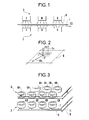
- FIG. 1 shows an elevational view of a known device applying this principle to a relatively thin sheet metal plate.
- - in reference 1 the support plate which extends horizontally between two networks of devices ("poles") generating magnetic fields
- - in reference 2 a lower network of poles alternately of North polarity marked N and of South polarity marked S
- - And in reference 3 a symmetrical upper network of precedent, the poles of the same polarity being opposite, the magnetic field created being represented by arrows H.
- FIG. 2 represents an element (or “mesh”) belonging to a support plate, located between two facing poles, and corresponding to this pair of poles.
- This element has the shape of a quadrilateral Q. It is for example square, and is part of a regular two-dimensional network which extends over the entire surface of the plate and results from the corresponding regular arrangement of the N and S poles.
- the through component of the field Hv induces a current i at a point P where the tangential component of the field is Hh.
- This component and this current create, according to Laplace's law, a vertical lifting force FS applied at P. If the plate is equidistant from the two identical poles, the traversing component Hv is zero (by symmetry) and the force FS also . The plate then approaches the lower network until the lift forces such as FS become large enough to support it.
- the poles are formed by coils traversed by an excitation current and possibly surrounding a laminated magnetic circuit: here we designate by "coil” the well-known device consisting of a relatively thin electrical conductor wound in loops (or “ more or less numerous coaxial coils.
- the poles are arranged in a manner adapted to the shape of the parts to be supported. To support a flat horizontal plate the poles are distributed on and under the plate as shown in Figure 3.
- the coils of the lower network 2 are marked NB and SB and those of the upper network 3, NH and SH respectively.
- Connection wires must be placed between the coils: NB and SB coils in the same row are for example connected in series, by wires such as 5 and 7 assigned to this row and they same connected respectively to wires such as 9 and 11 common to all the rows of the same network.
- Electromagnetic lift device for supporting without contact an electrically conductive part (1) above a lift area (AU), that is to say to maintain a distance between this part and this area against the action of a force such as gravity which pushes this part towards this area, this device comprising: - a source of alternating electrical excitation current (G), - at least one linear electrical excitation conductor (F) supplied by this source and traversing said lift area at least under said part to be lifted, to form in this area a two-dimensional network of magnetic poles (N, S), whose magnetic field lines move away from this area, this network having a configuration similar to that of a checkerboard with boxes in the form of quadrilaterals (A) juxtaposed, two adjacent squares by a common side being occupied by two poles of always opposite polarities, one of these pole
- each said sawtooth path (T1) s 'deviating from its axis alternately in one direction and in the other, two so-called any consecutive sawtooth paths (T1, T2) constituting a preceding path (T1) and a following path (T2) and being arranged so that the points of the preceding path which come closest to the axis (A2) of the following path are opposite the points of the following path which come closest to the axis (A1) of the preceding path, but without these two paths cross, two such points then forming a zone of maximum proximity (P, J) ent re the two paths, these proximity zones between two paths following each other in said second direction, these two paths then drawing between them, at least approximately, in this second direction, a row of said quadrilaterals each situated between two consecutive proximity zones, the succession of
- a first said path (T1) is electrically supplied from an input end (EE) of this path on one side of said succession of paths, and characterized in that the number of said paths is even, so that a last path (T6) ends on the same side of this succession, an additional path (TS) starting from the exit end of this last path, going towards said end of entry (EE) of the first path and also being jagged on either side of a mean axis (AS) which extends in said first direction (D1), this additional path approaching each of said zones of junction (J2) of even rank, without electrical contact, and moving away between these zones, and ending at an outlet end (ES) next to said inlet end (EE), so as to draw a column of additional quadrilaterals of said two-dimensional network and forming additional magnetic poles d In said lift area, with a minimum length of conductor and without crossing.
- the excitation conductor used according to the present invention is of a relatively large section to transport a current of higher intensity than the wires of the known devices. Its large section is allowed by the absence of any juxtaposition, superposition or crossing. It contributes to the robustness of the device. This absence of superimposition or crossing simplifies the problems of electrical insulation.
- the conductor may possibly be hollow and traversed by a stream of cooling water.
- a device in accordance with the invention is produced in the form of a conductor carrying the excitation current and arranged in a zig-zag on the lift area as indicated in FIG. 4. This device corresponds to all of points 1 to 6 above:
- two input terminals A and output B of the excitation alternating current are placed in front of the right lateral edge of a rectangular lift area AU, this edge being parallel to the direction of movement D2 of the lift plate 1 of Fig 1.
- the excitation conductor F is bent along a broken line, the segments of which are inclined at 45 ° to the edges of the area.
- Six sawtooth paths T1 to T6 have been shown succeeding each other over the entire width of the lift area; when we have reached the other lateral edge (the left edge) of this area, (at the end of the T6 path), we extend the conductor, always in a zig-zag, along the front edge to complete covering the length of the area until returning to the exit terminal B next to A.
- Each quadrilateral such as Q works, from an electro-magnetic point of view, like a turn as it appears when we observe the arrows such as IE which represent the current flowing in the conductor at a given time. It generates perpendicularly to the plane of the figure, substantially the same magnetic field at the frequency of the excitation current as a coil centered in its place would do.
- the device of FIG. 4 creates the same network of magnetic poles as that of FIG. 3: the directions of the magnetic fields are alternated in staggered rows, as represented by the N and S poles generated by the flow of current according to the IE arrows and are always opposite for two adjacent quadrilaterals.
- FIGS. 5, 6 and 7 Some of these modes are illustrated by FIGS. 5, 6 and 7 in which the current input and output terminals are always marked A and B, respectively.
- the mesh does not have to be square; it can be diamond-shaped to achieve - preferably although not necessarily an entire number of sections exactly covering the desired lift area; it can be curvilinear like that formed by the conductor FB shown in FIG. 6. It is expedient that the mesh is of regular shape because this represents an additional advantage relative to the "coil" arrangement of FIG. 3.
- the conductor can be full , or hollow to be internally cooled, or filamentary ...; it can receive protection (enameling), be fixed or worn if necessary by insulating devices placed, for example, in proximity zones P.
- Terminals A and B can be placed in any location; we can place several couples as shown in fig. 5 where the conductor is marked FA.
- a non-planar part can be supported by adapting to it a curvature of the surface of a two-dimensional network of poles; it is possible in particular to support a cylindrical object by winding around (or inside) a network formed by a conductor FC on a coaxial cylinder, in accordance with FIG. 7.
- An advantage of the present intention lies in the fact that the known lift devices with reels very generally require protection against the thermal radiation of the lifted parts and / or against the danger of a fall of the part on the device in the event of failure of current.
- This protection is carried out in the form of a screen which is arranged between the lifted part and the coils and which has various drawbacks: - It greatly limits the possibilities of observing the surface of the lifted part. - It practically prevents it from being blown (water, air) - The distance between the lifted part and the coils (the air gap, which should be minimized) must include the thickness of the screen and its own support structures.
- the air gap becomes equal to the "mechanical guard”, that is to say to the necessary space to allow any irregularities or protrusions of a part to be treated to pass. Its reduction makes it possible to reduce the electrical consumption of the device.
Abstract
Description
La sustentation électromagnétique, appelée parfois "lévitation" est un procédé connu en soi (voir, par exemple, le brevet FR 8202679 du 18.02.82 publié sous le no 2521797). Il est utilisé dans les laboratoires et l'industrie, par exemple pour la sustentation des rotors (paliers magnétiques), et en métallurgie pour la manutention de blocs métalliques (four pour traitements thermiques) ou de métaux liquides.The magnetic levitation, sometimes called "levitation" is a known process (see, for example, patent FR 8,202,679 of 02/18/82 published under No. 2521797). It is used in laboratories and industry, for example for the levitation of rotors (magnetic bearings), and in metallurgy for the handling of metal blocks (oven for heat treatments) or liquid metals.
Pour obtenir une sustentation il faut, en principe, faire traverser par un champ magnétique alternatif une pièce qui, pour l'obtention d'un meilleur résultat, doit être aussi peu magnétique et aussi bonne conductrice de l'électricité que possible. Cette pièce présente souvent la forme d'une plaque horizontale, ou analogue.Au niveau de la pièce, ce champ a deux composantes perpendiculaires :
-l'une verticale (parallèle à la pesanteur et perpendiculaire à la pièce) qu'on peut appeler composante " traversante" du champ,
-l'autre horizontale qu'on peut appeler "composante tangentielle" parcequ'elle est parallèle à la pièce.In order to obtain a lift, it is, in principle, necessary to pass through an alternating magnetic field a part which, for obtaining a better result, must be as little magnetic and as good conductor of electricity as possible. This part often has the shape of a horizontal plate, or the like. At the level of the part, this field has two perpendicular components:
-a vertical (parallel to gravity and perpendicular to the workpiece) which can be called the "through" component of the field,
-the other horizontal which we can call "tangential component" because it is parallel to the part.
Le flux de la composante verticale traversante engendre dans la pièce des courants induits. Suivant la loi de Laplace, ces derniers coopèrent avec la composante tangentielle du champ pour créer des forces verticales. Si la géométrie du système est convenable, cette force s'oppose à la gravité et "sustente" la pièce. La figure 1 montre une vue en élévation d'un dispositif connu appliquant ce principe à une plaque de tôle relativement mince. On y voit:
- en repère 1 : la plaque à sustenter qui s'étend horizontalement entre deux réseaux de dispositifs ("pôles") générateurs de champs magnétiques
- en repère 2 : un réseau inférieur de pôles alternativement de polarité Nord repèrés N et de polarité Sud repèrés S,
- et en repère 3 : un réseau supérieur symétrique de précédent, les pôles de même polarité étant vis-à-vis, le champ magnétique créé étant représenté par des flèches H.
Il n'est pas indispensable en principe d'utiliser deux réseaux de pôles ni que, dans ce cas, les pôles en vis-à-vis soient de même polarité mais cette disposition donne un meilleur rendement au dispositif. En effet, si les pôles en vis à vis sont de polarités opposées, on privilégie excessivement le flux traversant qui entraine alors un échauffement indésirable par pertes Joule dans la pièce sustentée.The flow of the vertical through component generates induced currents in the room. According to Laplace's law, the latter cooperate with the tangential component of the field to create vertical forces. If the geometry of the system is suitable, this force opposes gravity and "sustains" the part. Figure 1 shows an elevational view of a known device applying this principle to a relatively thin sheet metal plate. We see:
- in reference 1: the support plate which extends horizontally between two networks of devices ("poles") generating magnetic fields
- in reference 2: a lower network of poles alternately of North polarity marked N and of South polarity marked S,
- And in reference 3: a symmetrical upper network of precedent, the poles of the same polarity being opposite, the magnetic field created being represented by arrows H.
It is not essential in principle to use two arrays of poles or that, in this case, the opposite poles are of the same polarity but this arrangement gives a better performance to the device. Indeed, if the facing poles are of opposite polarities, excessive preference is given to the through flow which then causes undesirable heating by Joule losses in the lifted part.
La figure 2 représente un élément (ou "maille") appartenant à une plaque à sustenter, situé entre deux pôles en vis-à-vis, et correspondant à cette paire de pôles. Cet élément présente la forme d'un quadrilatère Q. Il est par exemple carré, et fait partie d'un réseau régulier bidimensionnel qui s'étend sur toute la surface de la plaque et résulte de la disposition régulière correspondante des pôles N et S. La composante traversante du champ Hv induit un courant i en un point P où la composante tangentielle du champ est Hh. Cette composante et ce courant créent, selon la loi de Laplace, une force verticale de sustentation FS appliquée en P. Si la plaque est équidistante des deux réseaux identiques de pôles , la composante traversante Hv est nulle (par symétrie) et la force FS aussi. La plaque se rapproche alors du réseau inférieur jusqu'à ce que les forces de sustentation telles que FS deviennent suffisamment importantes pour la soutenir.FIG. 2 represents an element (or “mesh”) belonging to a support plate, located between two facing poles, and corresponding to this pair of poles. This element has the shape of a quadrilateral Q. It is for example square, and is part of a regular two-dimensional network which extends over the entire surface of the plate and results from the corresponding regular arrangement of the N and S poles. The through component of the field Hv induces a current i at a point P where the tangential component of the field is Hh. This component and this current create, according to Laplace's law, a vertical lifting force FS applied at P. If the plate is equidistant from the two identical poles, the traversing component Hv is zero (by symmetry) and the force FS also . The plate then approaches the lower network until the lift forces such as FS become large enough to support it.
Dans les dispositifs actuellement réalisés les pôles sont formés par des bobines parcourues par un courant excitateur et entourant éventuellement un circuit magnétique feuilleté : on désigne ici par "bobine" le dispositif bien connu constitué d'un conducteur électrique relativement fin enroulé en boucles (ou "spires") coaxiales plus ou moins nombreuses.In the devices currently produced, the poles are formed by coils traversed by an excitation current and possibly surrounding a laminated magnetic circuit: here we designate by "coil" the well-known device consisting of a relatively thin electrical conductor wound in loops (or " more or less numerous coaxial coils.
Les pôles sont disposés de manière adaptée à la forme de pièces à sustenter. Pour soutenir une plaque horizontale plane les pôles sont répartis sur et sous la plaque comme l'indique la figure 3. Les bobines du réseau inférieur 2 sont repérées NB et SB et celles du réseau supérieur 3, NH et SH respectivement.The poles are arranged in a manner adapted to the shape of the parts to be supported. To support a flat horizontal plate the poles are distributed on and under the plate as shown in Figure 3. The coils of the
On doit placer entre les bobines des fils de connection : les bobines NB et SB d'une même rangée sont par exemple connectées en série, par des fils tels que 5 et 7 affectés à cette rangée et eux- mêmes connectés respectivement à des fils tels que 9 et 11 communs à toutes les rangées d'un même réseau.Connection wires must be placed between the coils: NB and SB coils in the same row are for example connected in series, by wires such as 5 and 7 assigned to this row and they same connected respectively to wires such as 9 and 11 common to all the rows of the same network.
Ces dispositifs utilisant des bobines présentent, sur le plan pratique, des inconvénients créés par l'encombrement du plan de pose et par leur fragilité vis à vis des agressions d'origines diverses auxquelles ils sont exposés :These devices using coils have, on a practical level, drawbacks created by the size of the laying surface and by their fragility with respect to attacks from various origins to which they are exposed:
Ces inconvénients sont notamment les suivants :
- L'aire de sustentation, sur et sous la plaque, est fortement occupée par les bobines avec leurs fils de connection ce qui limite ou interdit la mise en place de dispositifs utiles (chauffage ou réfrigération, contrôle ou mesure ...). Ceci est exprimé en disant que le dispositif est trop peu transparent.
- Les bobines et fils de connection sont nécessairement réalisés en fils isolés par un vernis ou émail isolant, car ces fils se touchent et se croisent en de nombreux points. Ils constituent des ensembles relativement complexes et fragiles notamment en présence de plaques chaudes.These disadvantages include the following:
- The lift area, on and under the plate, is heavily occupied by the coils with their connection wires which limits or prohibits the installation of useful devices (heating or refrigeration, control or measurement ...). This is expressed by saying that the device is too little transparent.
- The coils and connection wires are necessarily made of wires insulated by an insulating varnish or enamel, because these wires touch and cross at many points. They constitute relatively complex and fragile assemblies, in particular in the presence of hot plates.
La présente invention vise à réaliser la sustentation magnétique en éliminant ces inconvénients grâce à un dispositif transparent et robuste. Et son objet peut être décrit, de manière d'abord générale, par les points suivants, notamment :
1/ Dispositif de sustentation électromagnétique pour supporter sans contact une pièce électriquement conductrice (1) au-dessus d'une aire de sustentation (AU) c'est-à-dire pour maintenir une distance entre cette pièce et cette aire contre l'action d'une force telle que la gravité qui pousse cette pièce vers cette aire, ce dispositif comportant :
- une source de courant électrique alternatif d'excitation (G), - au moins un conducteur électrique linéaire d'excitation (F) alimenté par cette source et parcourant ladite aire de sustentation au moins sous ladite pièce à sustenter, pour former dans cette aire un réseau bidimensionnel de pôles magnétiques (N,S), dont les lignes de champ magnétique s'éloignent de cette aire, ce réseau présentant une configuration analogue à celle d'un damier avec des cases en forme de quadrilatères (A) juxtaposés, deux cases adjacentes par un côté commun étant occupées par deux pôles de polarités toujours opposées, l'un de ces pôles (N) étant Nord quand l'autre (S) est Sud et réciproquement, de manière à créer dans ladite pièce à sustenter (1) à la fois, d'une part, des composantes de champ magnétique traversantes, engendrant des courants parallèles à ladite aire, et d'autre part des composantes de champ magnétique tangentielles parallèles à cette aire et croisant ces courants pour engendrer des forces de sustentation (FS) perpendiculaires à cette aire,
- ce dispositif étant caractérisé par le fait que ledit conducteur d'excitation (F) suit, dans ladite aire de sustentation, une succession de trajets en dents de scie, (T1, T2...T6) qui se succèdent selon une première direction (D1) et présentent chacun un axe moyen (A1) selon une seconde direction (D2) inclinée sur la première, de manière à couvrir au moins une partie substantielle de cette aire de sustentation, chaque dit trajet en dents de scie (T1) s'écartant de son axe alternativement dans un sens et dans l'autre, deux dits trajets en dents de scie consécutifs quelconques (T1, T2) constituant un trajet précédent (T1) et un trajet suivant (T2) et étant disposés de sorte que les points du trajet précédent qui se rapprochent le plus de l'axe (A2) du trajet suivant soient en regard des points du trajet suivant qui se rapprochent le plus de l'axe (A1) du trajet précédent, mais sans que ces deux trajets se croisent, deux tels points formant alors une zone de proximité maximale (P,J) entre les deux trajets, ces zones de proximité entre deux trajets se succédant selon ladite deuxième direction, ces deux trajets dessinant alors entre eux, au moins approximativement, selon cette deuxième direction, une rangée de dits quadrilatères situés chacun entre deux zones de proximité consécutives, la succession desdits trajets en dents de scie formant une succession de telles rangées de quadrilatères et formant en même temps au moins une partie dudit réseau bidimensionnel, les quadrilatères adjacents par un côté commun étant alignés selon une troisième (D3) et une quatrième (D4) directions présentant des obliquités opposées par rapport à n'importe laquelle des dites première et deuxième directions, - le courant électrique d'excitation parcourant ledit trajet suivant (T2) étant d'un sens opposé à celui du courant dans ledit trajet précédent (T1), de manière à former une rangée de pôles magnétiques (S) d'une même polarité dans la rangée de quadrilatères dessinés entre ces deux trajets (T1, T2), à former de même une rangée de pôles magnétiques (N) de la polarité opposée dans la rangée de quadrilatères suivante (T2, T3) et ainsi de suite alternativement, ce qui entraîne en même temps que lesdits pôles ont lesdites polarités toujours opposées dans deux dites cases adjacentes par un côté commun, et ce qui permet finalement de former ledit réseau de pôles avec une longueur de conducteur et un nombre de rencontres de conducteurs diminués.
2/ Dispositif selon le point 1 caractérisé par le fait que ledit trajet précédent (T1) rejoint ledit trajet suivant (T2) dans zone de jonction (J1) qui est une dite zone de proximité à une extrémité commune de ces deux trajets, ce trajet suivant rejoignant lui-même le trajet encore suivant (T3) dans une zone de jonction suivante (J2) qui est une zone de proximité à l'autre extrémité de ce trajet, et ainsi de suite, de manière à réaliser une connexion électrique des trajets successifs en série.
3/ Dispositif selon le point 2 dans lequel un premier dit trajet (T1) est alimenté électriquement à partir d'une extrémité d'entrée (EE) de ce trajet d'un côté de ladite succession de trajets, et caractérisé par le fait que le nombre desdits trajets est pair, de sorte qu'un dernier trajet (T6) se termine du même côté de cette succession, un trajet supplémentaire (TS) partant de l'extrémité de sortie de ce dernier trajet, allant vers ladite extrémité d'entrée (EE) du premier trajet et étant également en dents de scie de part et d'autre d'un axe moyen (AS) qui s'étend selon ladite première direction (D1), ce trajet supplémentaire se rapprochant de chacune desdites zones de jonction (J2) de rang pair, sans contact électrique, et s'éloignant entre ces zones, et se terminant à une extrémité de sortie (ES) à côté de ladite extrémité d'entrée (EE), de manière à dessiner une colonne de quadrilatères supplémentaires dudit réseau bidimensionnel et à former des pôles magnétiques supplémentaires dans ladite aire de sustentation, avec une longueur minimale de conducteur et sans croisement.
4/Dispositif selon le point 1 caractérisé par le fait que lesdits quadrilatères sont des carrés dont les côtés sont orientés selon desdites troisième (D3) et quatrième (D4) directions à 45 degrés desdites première (D1) et deuxième (D2) directions, lesdits trajets (T1...T6) se succédant avec un pas égal à celui des dents de scie de chacun de ces trajets, de manière à constituer un dispositif de sustentation rectangulaire sur la surface et sur les bords duquel la pression de sustentation soit sensiblement constante.
5/Dispositif selon le point 4, appliqué à la sustentation d'une tole (1) défilant selon une direction de transfert, et caractérisé par le fait que cette direction de transfert (D2) constitue l'une desdites première (D1) et deuxième (D2) directions.
6/Dispositif selon le point 1 caractérisé par le fait qu'il comporte deux dits réseaux bidimensionnels de part et d'autre d'un intervalle pour le passage d'une pièce à sustenter, les pôles magnétiques de chaque polarité formés par l'un de ces réseaux étant en regard des pôles magnétiques de la même polarité formés par l'autre.The present invention aims to achieve magnetic levitation by eliminating these drawbacks thanks to a transparent and robust device. And its object can be described, in a general way first, by the following points, in particular:
1 / Electromagnetic lift device for supporting without contact an electrically conductive part (1) above a lift area (AU), that is to say to maintain a distance between this part and this area against the action of a force such as gravity which pushes this part towards this area, this device comprising:
- a source of alternating electrical excitation current (G), - at least one linear electrical excitation conductor (F) supplied by this source and traversing said lift area at least under said part to be lifted, to form in this area a two-dimensional network of magnetic poles (N, S), whose magnetic field lines move away from this area, this network having a configuration similar to that of a checkerboard with boxes in the form of quadrilaterals (A) juxtaposed, two adjacent squares by a common side being occupied by two poles of always opposite polarities, one of these poles (N) being North when the other (S) is South and vice versa, so as to create in said piece to be supported (1) at once, d on the one hand, through magnetic field components, generating currents parallel to said area, and on the other hand tangential magnetic field components parallel to this area and crossing these currents to generate lift forces (FS) perpendicular to this area,
- This device being characterized in that said excitation conductor (F) follows, in said lift area, a succession of sawtooth paths, (T1, T2 ... T6) which follow one another in a first direction (D1) and each have a mean axis (A1) in a second direction (D2) inclined on the first, so as to cover at least a substantial part of this lift area, each said sawtooth path (T1) s 'deviating from its axis alternately in one direction and in the other, two so-called any consecutive sawtooth paths (T1, T2) constituting a preceding path (T1) and a following path (T2) and being arranged so that the points of the preceding path which come closest to the axis (A2) of the following path are opposite the points of the following path which come closest to the axis (A1) of the preceding path, but without these two paths cross, two such points then forming a zone of maximum proximity (P, J) ent re the two paths, these proximity zones between two paths following each other in said second direction, these two paths then drawing between them, at least approximately, in this second direction, a row of said quadrilaterals each situated between two consecutive proximity zones, the succession of said sawtooth paths forming a succession of such rows of quadrilaterals and at the same time forming at least part of said two-dimensional network, the adjacent quadrilaterals by a common side being aligned in a third (D3) and a fourth (D4) directions having opposite obliquities with respect to any of said first and second directions, - the electric excitation current flowing through said following path (T2) being in a direction opposite to that of the current in said preceding path (T1), so as to form a row of magnetic poles (S) of the same polarity in the row of quadrilaterals drawn between these two paths (T1 , T2), likewise to form a row of magnetic poles (N) of the opposite polarity in the next row of quadrilaterals (T2, T3) and so on alternately, which at the same time means that said poles always have said polarities opposite in two said adjacent boxes by a common side, and which finally makes it possible to form said network of poles with a length of conductor and a reduced number of conductor encounters.
2 / Device according to
3 / Device according to
4 / Device according to
5 / Device according to point 4, applied to the lift of a sheet (1) moving in a direction of transfer, and characterized in that this direction of transfer (D2) constitutes one of said first (D1) and second (D2) directions.
6 / Device according to
Le conducteur d'excitation utilisé selon la présente invention est d'une section relativement grande pour transporter un courant d'intensité plus élevé que les fils des dispositifs connus. Sa forte section est permise par l'absence de toute juxtaposition, superposition ou croisement. Elle contribue à la robustesse du dispositif. Cette absence de superposition ou croisement simplifie les problèmes d'isolement électrique. Le conducteur peut éventuellement être creux et parcouru par un courant d'eau de réfrigération.The excitation conductor used according to the present invention is of a relatively large section to transport a current of higher intensity than the wires of the known devices. Its large section is allowed by the absence of any juxtaposition, superposition or crossing. It contributes to the robustness of the device. This absence of superimposition or crossing simplifies the problems of electrical insulation. The conductor may possibly be hollow and traversed by a stream of cooling water.
A l'aide des figures schématiques ci-jointes on va décrire plus particulièrement ci-après, à titre d'exemple non limitatif, comment la présente invention peut être mise en oeuvre dans le cadre de l'exposé qui en a été donné ci-dessus. Lorsqu'un même élément est représenté sur plusieurs figures il y est désigné par le même signe de référence. Lorsqu'un de ces signes de référence a été employé ci-dessus c'était pour permettre de se référer à ces mêmes figures à titre d'exemple non limitatif. Il doit être compris que les éléments mentionnés peuvent être remplacés par d'autres éléments assurant les mêmes fonctions techniques.
- La figure 1 représente une vue en élévation d'un dispositif de sustentation connu, comme précédemment indiqué, et en même temps d'un premier dispositif selon l'invention.
- La figure 2 représente une vue en perspective pour montrer les directions de composantes de champ magnétique, celle d'un courant induit dans une plaque à sustenter, et celle d'une force de sustentation en résultant aussi bien dans le cas d'un dispositif connu que selon l'invention.
- La figure 3 représente une vue en perpspective d'un dispositif de sustentation connu.
- La figure 4 représente une vue de dessus d'un réseau bidimensionnel de pôles du dispositif de la Fig 1 selon l'invention.
- Les Fig 5 et 6 représentent des vues de dessus de deux réseaux bidimensionnels de pôles d'un deuxième et d'un troisième dispositifs selon l'invention, respectivement.
- La Fig 7 représente une vue en perspective d'un réseau bidimensionnel de pôles d'un quatrième dispositif selon l'invention.
- Figure 1 shows an elevational view of a known lift device, as previously indicated, and at the same time of a first device according to the invention.
- FIG. 2 represents a perspective view to show the directions of magnetic field components, that of an induced current in a support plate, and that of a resultant support force as well in the case of a known device according to the invention.
- FIG. 3 represents a perspective view of a known lifting device.
- FIG. 4 represents a top view of a two-dimensional network of poles of the device of FIG 1 according to the invention.
- FIGS. 5 and 6 represent top views of two two-dimensional networks of poles of a second and a third device according to the invention, respectively.
- Fig 7 shows a perspective view of a two-dimensional network of poles of a fourth device according to the invention.
Comme précédemment indiqué un dispositif conforme à l'invention, est réalisé sous la forme d'un conducteur transportant le courant d'excitation et disposé en zig-zag sur l'aire de sustantation comme l'indique la figure 4. Ce dispositif correspond à l'ensemble des points 1 à 6 ci-dessus :As previously indicated, a device in accordance with the invention is produced in the form of a conductor carrying the excitation current and arranged in a zig-zag on the lift area as indicated in FIG. 4. This device corresponds to all of
Conformément à cette figure, deux bornes d'entrée A et de sortie B du courant alternatif d'excitation sont placées à l'avant du bord latéral droit d'une aire de sustentation rectangulaire AU, ce bord étant parallèle à la direction du déplacement D2 de la plaque sustentée 1 de la Fig 1.According to this figure, two input terminals A and output B of the excitation alternating current are placed in front of the right lateral edge of a rectangular lift area AU, this edge being parallel to the direction of movement D2 of the
Le conducteur d'excitation F est plié, selon une ligne brisée dont les segments sont inclinés à 45° sur les bords de l'aire . On a représenté six trajets en dents de scie T1 à T6 se succédant sur toute la largeur de l'aire de sustentation ; quand on a atteint l'autre bord latéral (le bord gauche) de cette aire, (à l' extrémité du trajet T6), on prolonge le conducteur, toujours en zig-zag, selon le bord avant pour achever de couvrir la longueur de l'aire jusqu'à revenir à la borne de sortie B voisine de A.The excitation conductor F is bent along a broken line, the segments of which are inclined at 45 ° to the edges of the area. Six sawtooth paths T1 to T6 have been shown succeeding each other over the entire width of the lift area; when we have reached the other lateral edge (the left edge) of this area, (at the end of the T6 path), we extend the conductor, always in a zig-zag, along the front edge to complete covering the length of the area until returning to the exit terminal B next to A.
Il n'y a pas de contact entre les trajets successifs du conducteur F dans les zones de proximité P situées aux coins des quadrilatères approximativement dessinés par le conducteur plié.There is no contact between the successive paths of the conductor F in the proximity zones P situated at the corners of the quadrilaterals roughly drawn by the folded conductor.
Chaque quadrilatère tel que Q fonctionne, du point de vue électro-magnétique, comme une spire ainsi qu'il apparaît quand on observe les flèches telles que IE qui représentent le courant circulant dans le conducteur à un instant donné. Il engendre perpendiculairement au plan de la figure, sensiblement le même champ magnétique à la fréquence du courant excitateur que le ferait une bobine centrée à sa place. Il en résulte que le dispositif de la figure 4 crée le même réseau de pôles magnétiques que celui de la figure 3 : les sens des champs magnétiques sont alternés en quinconce, comme représenté par les pôles N et S engendrés par la circulation du courant selon les flèches IE et sont toujours opposés pour deux quadrilatères adjacents.Each quadrilateral such as Q works, from an electro-magnetic point of view, like a turn as it appears when we observe the arrows such as IE which represent the current flowing in the conductor at a given time. It generates perpendicularly to the plane of the figure, substantially the same magnetic field at the frequency of the excitation current as a coil centered in its place would do. As a result, the device of FIG. 4 creates the same network of magnetic poles as that of FIG. 3: the directions of the magnetic fields are alternated in staggered rows, as represented by the N and S poles generated by the flow of current according to the IE arrows and are always opposite for two adjacent quadrilaterals.
Divers autres modes de réalisation de l'invention sont possibles. Certains de ces modes sont illustrés par les figures 5, 6 et 7 sur lesquelles les bornes d'entrée et de sortie du courant sont toujours repérées A et B, respectivement.Various other embodiments of the invention are possible. Some of these modes are illustrated by FIGS. 5, 6 and 7 in which the current input and output terminals are always marked A and B, respectively.
S'il est nécessaire, conformément à l'invention, que le conducteur F suive au moins approximativement les côtés des mailles d'un réseau de quadrilatères couvrant l'aire de sustentation sans contact entre brins adjacents (notamment aux coins des "quadrilatères"), il n'est pas nécessaire que la maille soit carrée ; elle peut être en losange pour réaliser - de préférence quoique non nécessairement un nombre entier de tronçons recouvrant exactement l'aire de sustentation souhaitée ; elle peut être curviligne comme celle formée par le conducteur FB représenté sur la figure 6. Il est opportun que la maille soit de forme régulière car ceci représente un avantage supplémentaire relativement à la disposition "en bobines" de figure 3. Le conducteur peut être plein, ou creux pour être intérieurement refroidi, ou filamentaire ... ; il peut recevoir une protection (émaillage), être fixé ou porté si nécessaire par des dispositifs isolants placés, par exemple, dans les zones de proximité P. Les bornes A et B peuvent être placées en un lieu quelconque ; on peut en placer plusiers couples comme représenté en fig. 5 où le conducteur est repéré FA.If it is necessary, in accordance with the invention, for the conductor F to follow at least approximately the sides of the meshes of a network of quadrilaterals covering the lift area without contact between adjacent strands (in particular at the corners of the "quadrilaterals") , the mesh does not have to be square; it can be diamond-shaped to achieve - preferably although not necessarily an entire number of sections exactly covering the desired lift area; it can be curvilinear like that formed by the conductor FB shown in FIG. 6. It is expedient that the mesh is of regular shape because this represents an additional advantage relative to the "coil" arrangement of FIG. 3. The conductor can be full , or hollow to be internally cooled, or filamentary ...; it can receive protection (enameling), be fixed or worn if necessary by insulating devices placed, for example, in proximity zones P. Terminals A and B can be placed in any location; we can place several couples as shown in fig. 5 where the conductor is marked FA.
Conformément à l'invention, on peut sustenter une pièce non plane en lui adaptant une courbure de la surface d'un réseau bidimensionnel de pôles ; on peut notamment sustenter un objet cylindrique en enroulant autour (ou à l'intérieur) un réseau formé par un conducteur FC sur un cylindre coaxial, conformément à la fig 7.According to the invention, a non-planar part can be supported by adapting to it a curvature of the surface of a two-dimensional network of poles; it is possible in particular to support a cylindrical object by winding around (or inside) a network formed by a conductor FC on a coaxial cylinder, in accordance with FIG. 7.
On peut aussi utiliser plusieurs réseaux superposés, sans ou avec noyaux magnétiques.It is also possible to use several superimposed networks, with or without magnetic cores.
Un avantage de la présente intention tient au fait que les dispositifs de sustentation connus à bobines exigent très généralement une protection contre le rayonnement thermique des pièces sustentées et/ou contre le danger d'une chute de la pièce sur le dispositif en cas de panne de courant.An advantage of the present intention lies in the fact that the known lift devices with reels very generally require protection against the thermal radiation of the lifted parts and / or against the danger of a fall of the part on the device in the event of failure of current.
Cette protection est réalisée sous la forme d'un écran qui est disposé entre la pièce sustentée et les bobines et qui présente divers inconvénients :
- Il limite fortement les possibilités d'observation de la surface de la pièce sustentée.
- Il empêche pratiquement de la traiter par soufflage (eau, air)
- La distance entre la pièce sustentée et les bobines (l'entrefer, qu'on a intérêt à minimiser) doit englober l'épaisseur de l'écran et de ses structures de support propres.This protection is carried out in the form of a screen which is arranged between the lifted part and the coils and which has various drawbacks:
- It greatly limits the possibilities of observing the surface of the lifted part.
- It practically prevents it from being blown (water, air)
- The distance between the lifted part and the coils (the air gap, which should be minimized) must include the thickness of the screen and its own support structures.
Il y a de plus des difficultés de réalisation de cet écran : Il doit en effet être transparent au flux magnétique, donc non métallique, Il est par exemple constitué de matériaux céramiques ou fibreux et porté par un dispositif qui le relie à la structure à travers les bobines.There are also difficulties in producing this screen: It must indeed be transparent to magnetic flux, therefore non-metallic, It is for example made of ceramic or fibrous materials and carried by a device which connects it to the structure through the coils.
Ces difficultés et inconvénients disparaissent avec le dispositif selon l'invention, dont la robustesse permet d'éliminer l'écran. L'entrefer devient égal à la "garde mécanique" c'est-à-dire à l'invervalle nécessaire pour laisser passer les irrégularités ou saillies éventuelles d'une pièce à traiter. Sa réduction permet de diminuer la consommation électrique du dispositif.These difficulties and drawbacks disappear with the device according to the invention, the robustness of which eliminates the screen. The air gap becomes equal to the "mechanical guard", that is to say to the necessary space to allow any irregularities or protrusions of a part to be treated to pass. Its reduction makes it possible to reduce the electrical consumption of the device.
Claims (6)
- une source de courant électrique alternatif d'excitation (G), - au moins un conducteur électrique linéaire d'excitation (F) alimenté par cette source et parcourant ladite aire de sustentation au moins sous ladite pièce à sustenter, pour former dans cette aire un réseau bidimensionnel de pôles magnétiques (N,S), dont les lignes de champ magnétique s'éloignent de cette aire, ce réseau présentant une configuration analogue à celle d'un damier avec des cases en forme de quadrilatères (Q) juxtaposés, deux cases adjacentes par un côté commun étant occupées par deux pôles de polarités toujours opposées, l'un de ces pôles (N) étant Nord quand l'autre (S) est Sud et réciproquement, de manière à créer dans ladite pièce à sustenter (1) à la fois, d'une part, des composantes de champ magnétique traversantes engendrant des courants parallèles à ladite aire, et d'autre part des composantes de champ magnétique tangentielles parallèles à cette aire et croisant ces courants pour engendrer des forces de sustentation (FS) perpendiculaires à cette aire,
- ce dispositif étant caractérisé par le fait que ledit conducteur d'excitation (F) suit, dans ladite aire de sustentation, une succession de trajets en dents de scie, (T1, T2...T6) qui se succèdent selon une première direction (D1) et présentent chacun un axe moyen (A1) selon une seconde direction (D2) inclinée sur la première, de manière à couvrir au moins une partie substantielle de cette aire de sustentation, chaque dit trajet en dents de scie (T1) s'écartant de son axe alternativement dans un sens et dans l'autre, deux dits trajets en dents de scie consécutifs quelconques (T1, T2) constituant un trajet précédent (T1) et un trajet suivant (T2) et étant disposés de sorte que les points du trajet précédent qui se rapprochent le plus de l'axe (A2) du trajet suivant soient en regard des points du trajet suivant qui se rapprochent le plus de l'axe (A1) du trajet précédent, mais sans que ces deux trajets se croisent, deux tels points formant alors une zone de proximité maximale (P,J) entre les deux trajets, ces zones de proximité entre deux trajets se succédant selon ladite deuxième direction, ces deux trajets dessinant alors entre eux, au moins approximativement, selon cette deuxième direction,une rangée de dits quadrilatères situés chacun entre deux zones de proximité consécutives, la succession desdits trajets en dents de scie formant une succession de telles rangées de quadrilatères et formant en même temps au moins une partie dudit réseau bidimensionnel, les quadrilatères adjacents par un côté commun étant alignés selon une troisième (D3) et une quatrième (D4) directions présentant des obliquités opposées par rapport à n'importe laquelle des dites première et deuxième directions,
- le courant électrique d'excitation parcourant ledit trajet suivant (T2) étant d'un sens opposé à celui du courant dans ledit trajet précédent (T1), de manière à former une rangée de pôles magnétiques (S) d'une même polarité dans la rangée de quadrilatères dessinés entre ces deux trajets (T1, T2), à former de même une rangée de pôles magnétiques (N) de la polarité opposé dans la rangée de quadrilatères suivante (T2, T3) et ainsi de suite alternativement, ce qui entraîne en même temps que lesdits pôles ont lesdites polarités toujours opposées dans deux dites cases adjacentes par un côté commun, et ce qui permet finalement de former ledit réseau de pôles avec une longueur de conducteur et un nombre de rencontres de conducteurs diminués.1 / Electromagnetic lift device for supporting without contact an electrically conductive part (1) above a lift area (AU), that is to say to maintain a distance between this part and this area against the action of a force such as gravity which pushes this part towards this area, this device comprising:
- a source of alternating electrical excitation current (G), - at least one linear electrical excitation conductor (F) supplied by this source and traversing said lift area at least under said part to be lifted, to form in this area a two-dimensional network of magnetic poles (N, S), whose magnetic field lines move away from this area, this network having a configuration similar to that of a checkerboard with squares in the form of quadrilaterals (Q) juxtaposed, two adjacent boxes by a common side being occupied by two poles of polarities always opposite, one of these poles (N) being North when the other (S) is South and vice versa, so as to create in said room to be supported (1 ) both, on the one hand, through magnetic field components generating currents parallel to said area, and on the other hand tangential magnetic field components parallel to this area and crossing these currents to generate forces lift (FS) perpendicular to this area,
- This device being characterized in that said excitation conductor (F) follows, in said lift area, a succession of sawtooth paths, (T1, T2 ... T6) which follow one another in a first direction (D1) and each have a mean axis (A1) in a second direction (D2) inclined on the first, so as to cover at least a substantial part of this lift area, each said sawtooth path (T1) s 'deviating from its axis alternately in one direction and in the other, two so-called any consecutive sawtooth paths (T1, T2) constituting a preceding path (T1) and a following path (T2) and being arranged so that the points on the previous path that come closest to the axis (A2) of the following path are opposite the points of the following path which are closest to the axis (A1) of the previous path, but without these two paths crossing, two such points then forming a zone of maximum proximity (P, J ) between the two paths, these proximity zones between two paths following each other in said second direction, these two paths then drawing between them, at least approximately, in this second direction, a row of said quadrilaterals each located between two consecutive proximity zones , the succession of said sawtooth paths forming a succession of such rows of quadrilaterals and at the same time forming at least part of said two-dimensional network, the adjacent quadrilaterals by a common side being aligned according to a third (D3) and a fourth (D4 ) directions having opposite obliquities with respect to any of said first and second directions,
- the electric excitation current traversing said following path (T2) being in a direction opposite to that of the current in said preceding path (T1), so as to form a row of magnetic poles (S) of the same polarity in the row of quadrilaterals drawn between these two paths (T1, T2), likewise forming a row of magnetic poles (N) of opposite polarity in the next row of quadrilaterals (T2, T3) and so on alternately, which entails at the same time that said poles have said polarities always opposite in two said adjacent boxes by a common side, and which ultimately makes it possible to form said network of poles with a length of conductor and a reduced number of conductor encounters.
Priority Applications (1)
| Application Number | Priority Date | Filing Date | Title |
|---|---|---|---|
| AT87106891T ATE60175T1 (en) | 1986-05-14 | 1987-05-12 | ELECTROMAGNETIC LIFT DEVICE. |
Applications Claiming Priority (2)
| Application Number | Priority Date | Filing Date | Title |
|---|---|---|---|
| FR8606933 | 1986-05-14 | ||
| FR8606933A FR2598866A1 (en) | 1986-05-14 | 1986-05-14 | ELECTROMAGNETIC SUPPORT DEVICE |
Publications (2)
| Publication Number | Publication Date |
|---|---|
| EP0246550A1 true EP0246550A1 (en) | 1987-11-25 |
| EP0246550B1 EP0246550B1 (en) | 1991-01-16 |
Family
ID=9335227
Family Applications (1)
| Application Number | Title | Priority Date | Filing Date |
|---|---|---|---|
| EP87106891A Expired - Lifetime EP0246550B1 (en) | 1986-05-14 | 1987-05-12 | Electromagnetic levitation device |
Country Status (6)
| Country | Link |
|---|---|
| US (1) | US4761579A (en) |
| EP (1) | EP0246550B1 (en) |
| JP (1) | JPS62281407A (en) |
| AT (1) | ATE60175T1 (en) |
| DE (1) | DE3767361D1 (en) |
| FR (1) | FR2598866A1 (en) |
Cited By (2)
| Publication number | Priority date | Publication date | Assignee | Title |
|---|---|---|---|---|
| WO1995000773A1 (en) * | 1993-06-25 | 1995-01-05 | Jenoptik Gmbh | Anti-damage protecting system for a body driven in a plane |
| FR2730106A1 (en) * | 1995-01-31 | 1996-08-02 | Alsthom Cge Alcatel | SELF-STABILIZED MAGNETIC LEVITATION SYSTEM |
Families Citing this family (19)
| Publication number | Priority date | Publication date | Assignee | Title |
|---|---|---|---|---|
| US5015906A (en) * | 1989-11-03 | 1991-05-14 | Princeton University | Electrostatic levitation control system for micromechanical devices |
| FI90604C (en) * | 1991-02-07 | 1994-02-25 | Kone Oy | Asynchronous motor and method of manufacturing a stator and / or rotor of an asynchronous motor |
| US5168183A (en) * | 1991-03-27 | 1992-12-01 | The University Of British Columbia | Levitation system with permanent magnets and coils |
| JPH05133706A (en) * | 1991-07-30 | 1993-05-28 | Hitachi Metals Ltd | Phase sensing actuator |
| US5887018A (en) * | 1996-07-09 | 1999-03-23 | Wm. Marsh Rice University | Longitudinal electromagnetic levitator |
| SE508442C2 (en) * | 1997-01-28 | 1998-10-05 | Magnetal Ab | Electrodynamic magnetic bearing |
| US6441514B1 (en) | 1997-04-28 | 2002-08-27 | Ultratech Stepper, Inc. | Magnetically positioned X-Y stage having six degrees of freedom |
| US5886432A (en) * | 1997-04-28 | 1999-03-23 | Ultratech Stepper, Inc. | Magnetically-positioned X-Y stage having six-degrees of freedom |
| US6554745B2 (en) | 2000-08-14 | 2003-04-29 | Luc H. Pham | Exercise apparatus using magnetism to augment gravatational field |
| US6832518B1 (en) * | 2003-06-05 | 2004-12-21 | International Business Machines Corporation | Pressure wave sensor using levitated mass |
| US7235906B2 (en) * | 2004-05-10 | 2007-06-26 | Airex Corporation | Magnetic bearing using displacement winding techniques |
| US20060229160A1 (en) * | 2004-09-08 | 2006-10-12 | Srikrishna Talluri | System for creating artificial gravity conditions in micro and hypogravity environments |
| US9006914B2 (en) * | 2006-06-12 | 2015-04-14 | Uri Rapoport | Electromagnetic device for generating electrical current and methods thereof |
| US20100036394A1 (en) * | 2007-01-31 | 2010-02-11 | Yoav Mintz | Magnetic Levitation Based Devices, Systems and Techniques for Probing and Operating in Confined Space, Including Performing Medical Diagnosis and Surgical Procedures |
| US9757585B2 (en) * | 2007-06-05 | 2017-09-12 | P Tech, Llc | Magnetic joint implant |
| US8169114B2 (en) * | 2010-05-05 | 2012-05-01 | Martin Simon | Large gap horizontal field magnetic levitator |
| DE102011106523A1 (en) * | 2011-07-04 | 2013-01-10 | Giesecke & Devrient Gmbh | Test apparatus and method for calibrating a tester |
| US11300531B2 (en) | 2014-06-25 | 2022-04-12 | Aspect Ai Ltd. | Accurate water cut measurement |
| US10345251B2 (en) | 2017-02-23 | 2019-07-09 | Aspect Imaging Ltd. | Portable NMR device for detecting an oil concentration in water |
Citations (3)
| Publication number | Priority date | Publication date | Assignee | Title |
|---|---|---|---|---|
| FR1426389A (en) * | 1964-12-18 | 1966-01-28 | Method of constituting a magnetic or electro-magnetic plate for fixing metal parts | |
| DE2412221A1 (en) * | 1974-03-14 | 1975-09-18 | Weh Herbert | Differential fluid electrodynamic magnetic hover transport - with right angled figure eight shaped secondary coils parallel to primary coil planes |
| US4331896A (en) * | 1980-10-20 | 1982-05-25 | Sedgewick Richard D | Zig-zag windings, winding machine, and method |
Family Cites Families (4)
| Publication number | Priority date | Publication date | Assignee | Title |
|---|---|---|---|---|
| US3512852A (en) * | 1969-03-07 | 1970-05-19 | Atomic Energy Commission | Stabilized levitation of magnetic elements |
| DE2355697A1 (en) * | 1973-11-07 | 1975-05-15 | Siemens Ag | MAGNETIC SYSTEM FOR CONTACT-FREE GUIDANCE OF A MOVING VEHICLE |
| FR2521797B1 (en) * | 1982-02-18 | 1985-12-06 | Cem Comp Electro Mec | METHOD AND DEVICES FOR MINIMIZING THE INDUCED POWER IN A CONDUCTIVE FLAT PRODUCT MAINTAINED ELECTROMAGNETICALLY NON-CONTACT |
| US4585282A (en) * | 1983-07-19 | 1986-04-29 | Bosley Robert W | Magnetic levitation system |
-
1986
- 1986-05-14 FR FR8606933A patent/FR2598866A1/en not_active Withdrawn
-
1987
- 1987-05-12 AT AT87106891T patent/ATE60175T1/en not_active IP Right Cessation
- 1987-05-12 EP EP87106891A patent/EP0246550B1/en not_active Expired - Lifetime
- 1987-05-12 DE DE8787106891T patent/DE3767361D1/en not_active Expired - Fee Related
- 1987-05-13 JP JP62116687A patent/JPS62281407A/en active Granted
- 1987-05-13 US US07/049,174 patent/US4761579A/en not_active Expired - Fee Related
Patent Citations (3)
| Publication number | Priority date | Publication date | Assignee | Title |
|---|---|---|---|---|
| FR1426389A (en) * | 1964-12-18 | 1966-01-28 | Method of constituting a magnetic or electro-magnetic plate for fixing metal parts | |
| DE2412221A1 (en) * | 1974-03-14 | 1975-09-18 | Weh Herbert | Differential fluid electrodynamic magnetic hover transport - with right angled figure eight shaped secondary coils parallel to primary coil planes |
| US4331896A (en) * | 1980-10-20 | 1982-05-25 | Sedgewick Richard D | Zig-zag windings, winding machine, and method |
Cited By (2)
| Publication number | Priority date | Publication date | Assignee | Title |
|---|---|---|---|---|
| WO1995000773A1 (en) * | 1993-06-25 | 1995-01-05 | Jenoptik Gmbh | Anti-damage protecting system for a body driven in a plane |
| FR2730106A1 (en) * | 1995-01-31 | 1996-08-02 | Alsthom Cge Alcatel | SELF-STABILIZED MAGNETIC LEVITATION SYSTEM |
Also Published As
| Publication number | Publication date |
|---|---|
| EP0246550B1 (en) | 1991-01-16 |
| ATE60175T1 (en) | 1991-02-15 |
| FR2598866A1 (en) | 1987-11-20 |
| DE3767361D1 (en) | 1991-02-21 |
| JPH0318325B2 (en) | 1991-03-12 |
| JPS62281407A (en) | 1987-12-07 |
| US4761579A (en) | 1988-08-02 |
Similar Documents
| Publication | Publication Date | Title |
|---|---|---|
| EP0246550B1 (en) | Electromagnetic levitation device | |
| EP0462011B1 (en) | Induction heating coil | |
| EP0170556B1 (en) | Electromagnetic induction device for the heating of metallic elements | |
| FR2702119A1 (en) | Device for excitation of a plasma with electronic cyclotron resonance by means of a wired applicator of a microwave field and a static magnetic field. | |
| EP0808080A1 (en) | High efficiency induction cooking hob | |
| EP0527937B1 (en) | Process and devices for the induction heating of a moving elongate metallurgical product | |
| EP0072281A1 (en) | Composite thermal screen and method for its manufacture | |
| EP0617879A1 (en) | Induction furnace. | |
| EP0087345B1 (en) | Process and devices for minimizing the induced power in a flat conducting product suspended electromagnetically without contact | |
| EP2878071B1 (en) | Winding for a stator element of a permanent-magnet motor or generator, comprising at least one single-component, rigid limb, and method for producing same | |
| EP0628225A1 (en) | Induction module for an asynchronous linear electric motor and method for manufacturing same. | |
| EP0129160B1 (en) | Continuous-induction-heating arrangement for metallic products | |
| FR2536943A1 (en) | Method and device for the induction heating of a ferromagnetic component having axial symmetry and irregular contour. | |
| EP0013218B1 (en) | Induction heating apparatus for flat metallurgical products | |
| EP2488003A1 (en) | Electrical control unit using printed-circuit technology for the power-line conductor | |
| FR2495752A1 (en) | Induction furnace, esp. for heating long steel slab - using upper and lower row of induction heating modules sepd. by rollers on which slab rests | |
| EP0592324B1 (en) | Magnetic field protection device | |
| EP0295981B1 (en) | Electron curtain accelerator | |
| EP0221921B1 (en) | Ironless solenoidal magnet | |
| CH349756A (en) | Method of electric heating of a glass part and device for its implementation | |
| EP0639839A1 (en) | Device for magnetising or demagnetising metal workpieces | |
| FR2573947A1 (en) | Device for heating flat products on the move by electromagnetic induction according to a square grid | |
| MXPA96003973A (en) | Assembly of induction heating coil for the prevention of circulation currents in induction heating lines for products of foundry conti | |
| CH516888A (en) | Double-acting inductor linear motor | |
| BE688271A (en) |
Legal Events
| Date | Code | Title | Description |
|---|---|---|---|
| PUAI | Public reference made under article 153(3) epc to a published international application that has entered the european phase |
Free format text: ORIGINAL CODE: 0009012 |
|
| AK | Designated contracting states |
Kind code of ref document: A1 Designated state(s): AT BE CH DE FR GB IT LI LU NL SE |
|
| 17P | Request for examination filed |
Effective date: 19880525 |
|
| RAP1 | Party data changed (applicant data changed or rights of an application transferred) |
Owner name: GEC ALSTHOM SA |
|
| 17Q | First examination report despatched |
Effective date: 19900223 |
|
| GRAA | (expected) grant |
Free format text: ORIGINAL CODE: 0009210 |
|
| AK | Designated contracting states |
Kind code of ref document: B1 Designated state(s): AT BE CH DE FR GB IT LI LU NL SE |
|
| REF | Corresponds to: |
Ref document number: 60175 Country of ref document: AT Date of ref document: 19910215 Kind code of ref document: T |
|
| REF | Corresponds to: |
Ref document number: 3767361 Country of ref document: DE Date of ref document: 19910221 |
|
| GBT | Gb: translation of ep patent filed (gb section 77(6)(a)/1977) | ||
| ITF | It: translation for a ep patent filed |
Owner name: JACOBACCI & PERANI S.P.A. |
|
| PLBE | No opposition filed within time limit |
Free format text: ORIGINAL CODE: 0009261 |
|
| STAA | Information on the status of an ep patent application or granted ep patent |
Free format text: STATUS: NO OPPOSITION FILED WITHIN TIME LIMIT |
|
| 26N | No opposition filed | ||
| EPTA | Lu: last paid annual fee | ||
| EAL | Se: european patent in force in sweden |
Ref document number: 87106891.2 |
|
| PGFP | Annual fee paid to national office [announced via postgrant information from national office to epo] |
Ref country code: CH Payment date: 19950428 Year of fee payment: 9 |
|
| PG25 | Lapsed in a contracting state [announced via postgrant information from national office to epo] |
Ref country code: LI Effective date: 19960531 Ref country code: CH Effective date: 19960531 |
|
| REG | Reference to a national code |
Ref country code: CH Ref legal event code: PL |
|
| PGFP | Annual fee paid to national office [announced via postgrant information from national office to epo] |
Ref country code: GB Payment date: 19970410 Year of fee payment: 11 |
|
| PGFP | Annual fee paid to national office [announced via postgrant information from national office to epo] |
Ref country code: FR Payment date: 19970411 Year of fee payment: 11 |
|
| PGFP | Annual fee paid to national office [announced via postgrant information from national office to epo] |
Ref country code: BE Payment date: 19970417 Year of fee payment: 11 |
|
| PGFP | Annual fee paid to national office [announced via postgrant information from national office to epo] |
Ref country code: AT Payment date: 19970422 Year of fee payment: 11 |
|
| PGFP | Annual fee paid to national office [announced via postgrant information from national office to epo] |
Ref country code: SE Payment date: 19970423 Year of fee payment: 11 |
|
| PGFP | Annual fee paid to national office [announced via postgrant information from national office to epo] |
Ref country code: NL Payment date: 19970428 Year of fee payment: 11 Ref country code: LU Payment date: 19970428 Year of fee payment: 11 |
|
| PGFP | Annual fee paid to national office [announced via postgrant information from national office to epo] |
Ref country code: DE Payment date: 19970510 Year of fee payment: 11 |
|
| PG25 | Lapsed in a contracting state [announced via postgrant information from national office to epo] |
Ref country code: LU Free format text: LAPSE BECAUSE OF NON-PAYMENT OF DUE FEES Effective date: 19980512 Ref country code: GB Free format text: LAPSE BECAUSE OF NON-PAYMENT OF DUE FEES Effective date: 19980512 Ref country code: AT Free format text: LAPSE BECAUSE OF NON-PAYMENT OF DUE FEES Effective date: 19980512 |
|
| PG25 | Lapsed in a contracting state [announced via postgrant information from national office to epo] |
Ref country code: SE Free format text: LAPSE BECAUSE OF NON-PAYMENT OF DUE FEES Effective date: 19980513 |
|
| PG25 | Lapsed in a contracting state [announced via postgrant information from national office to epo] |
Ref country code: FR Free format text: LAPSE BECAUSE OF NON-PAYMENT OF DUE FEES Effective date: 19980531 Ref country code: BE Free format text: LAPSE BECAUSE OF NON-PAYMENT OF DUE FEES Effective date: 19980531 |
|
| BERE | Be: lapsed |
Owner name: S.A. GEC ALSTHOM Effective date: 19980531 |
|
| PG25 | Lapsed in a contracting state [announced via postgrant information from national office to epo] |
Ref country code: NL Free format text: LAPSE BECAUSE OF NON-PAYMENT OF DUE FEES Effective date: 19981201 |
|
| GBPC | Gb: european patent ceased through non-payment of renewal fee |
Effective date: 19980512 |
|
| EUG | Se: european patent has lapsed |
Ref document number: 87106891.2 |
|
| NLV4 | Nl: lapsed or anulled due to non-payment of the annual fee |
Effective date: 19981201 |
|
| PG25 | Lapsed in a contracting state [announced via postgrant information from national office to epo] |
Ref country code: DE Free format text: LAPSE BECAUSE OF NON-PAYMENT OF DUE FEES Effective date: 19990302 |
|
| REG | Reference to a national code |
Ref country code: FR Ref legal event code: ST |
|
| PG25 | Lapsed in a contracting state [announced via postgrant information from national office to epo] |
Ref country code: IT Free format text: LAPSE BECAUSE OF NON-PAYMENT OF DUE FEES;WARNING: LAPSES OF ITALIAN PATENTS WITH EFFECTIVE DATE BEFORE 2007 MAY HAVE OCCURRED AT ANY TIME BEFORE 2007. THE CORRECT EFFECTIVE DATE MAY BE DIFFERENT FROM THE ONE RECORDED. Effective date: 20050512 |