EP0246550A1 - Elektromagnetische Auftriebseinrichtung - Google Patents
Elektromagnetische Auftriebseinrichtung Download PDFInfo
- Publication number
- EP0246550A1 EP0246550A1 EP87106891A EP87106891A EP0246550A1 EP 0246550 A1 EP0246550 A1 EP 0246550A1 EP 87106891 A EP87106891 A EP 87106891A EP 87106891 A EP87106891 A EP 87106891A EP 0246550 A1 EP0246550 A1 EP 0246550A1
- Authority
- EP
- European Patent Office
- Prior art keywords
- path
- paths
- area
- lift
- quadrilaterals
- Prior art date
- Legal status (The legal status is an assumption and is not a legal conclusion. Google has not performed a legal analysis and makes no representation as to the accuracy of the status listed.)
- Granted
Links
- 238000005339 levitation Methods 0.000 title description 5
- 239000004020 conductor Substances 0.000 claims abstract description 27
- 230000005284 excitation Effects 0.000 claims abstract description 15
- 230000005484 gravity Effects 0.000 claims description 4
- 230000009471 action Effects 0.000 claims description 2
- 239000002184 metal Substances 0.000 abstract description 3
- 229910052751 metal Inorganic materials 0.000 abstract description 3
- 229910000831 Steel Inorganic materials 0.000 abstract 1
- 238000010276 construction Methods 0.000 abstract 1
- 239000010959 steel Substances 0.000 abstract 1
- 238000010438 heat treatment Methods 0.000 description 3
- 230000008901 benefit Effects 0.000 description 2
- 238000013459 approach Methods 0.000 description 1
- 238000003491 array Methods 0.000 description 1
- 230000000712 assembly Effects 0.000 description 1
- 238000000429 assembly Methods 0.000 description 1
- 239000000919 ceramic Substances 0.000 description 1
- 239000000498 cooling water Substances 0.000 description 1
- 210000003298 dental enamel Anatomy 0.000 description 1
- 238000010292 electrical insulation Methods 0.000 description 1
- 230000005611 electricity Effects 0.000 description 1
- 238000004534 enameling Methods 0.000 description 1
- 239000002657 fibrous material Substances 0.000 description 1
- 230000004907 flux Effects 0.000 description 1
- 238000009434 installation Methods 0.000 description 1
- 229910001338 liquidmetal Inorganic materials 0.000 description 1
- 238000005259 measurement Methods 0.000 description 1
- 238000005272 metallurgy Methods 0.000 description 1
- 238000000034 method Methods 0.000 description 1
- 230000008569 process Effects 0.000 description 1
- 230000005855 radiation Effects 0.000 description 1
- 230000009467 reduction Effects 0.000 description 1
- 238000005057 refrigeration Methods 0.000 description 1
- 239000002966 varnish Substances 0.000 description 1
- XLYOFNOQVPJJNP-UHFFFAOYSA-N water Substances O XLYOFNOQVPJJNP-UHFFFAOYSA-N 0.000 description 1
- 238000004804 winding Methods 0.000 description 1
Images

Classifications
-
- H—ELECTRICITY
- H02—GENERATION; CONVERSION OR DISTRIBUTION OF ELECTRIC POWER
- H02N—ELECTRIC MACHINES NOT OTHERWISE PROVIDED FOR
- H02N15/00—Holding or levitation devices using magnetic attraction or repulsion, not otherwise provided for
Definitions
- the magnetic levitation sometimes called “levitation” is a known process (see, for example, patent FR 8,202,679 of 02/18/82 published under No. 2521797). It is used in laboratories and industry, for example for the levitation of rotors (magnetic bearings), and in metallurgy for the handling of metal blocks (oven for heat treatments) or liquid metals.
- this part In order to obtain a lift, it is, in principle, necessary to pass through an alternating magnetic field a part which, for obtaining a better result, must be as little magnetic and as good conductor of electricity as possible.
- This part often has the shape of a horizontal plate, or the like.
- this field has two perpendicular components: -a vertical (parallel to gravity and perpendicular to the workpiece) which can be called the "through” component of the field, -the other horizontal which we can call “tangential component” because it is parallel to the part.
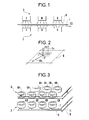
- FIG. 1 shows an elevational view of a known device applying this principle to a relatively thin sheet metal plate.
- - in reference 1 the support plate which extends horizontally between two networks of devices ("poles") generating magnetic fields
- - in reference 2 a lower network of poles alternately of North polarity marked N and of South polarity marked S
- - And in reference 3 a symmetrical upper network of precedent, the poles of the same polarity being opposite, the magnetic field created being represented by arrows H.
- FIG. 2 represents an element (or “mesh”) belonging to a support plate, located between two facing poles, and corresponding to this pair of poles.
- This element has the shape of a quadrilateral Q. It is for example square, and is part of a regular two-dimensional network which extends over the entire surface of the plate and results from the corresponding regular arrangement of the N and S poles.
- the through component of the field Hv induces a current i at a point P where the tangential component of the field is Hh.
- This component and this current create, according to Laplace's law, a vertical lifting force FS applied at P. If the plate is equidistant from the two identical poles, the traversing component Hv is zero (by symmetry) and the force FS also . The plate then approaches the lower network until the lift forces such as FS become large enough to support it.
- the poles are formed by coils traversed by an excitation current and possibly surrounding a laminated magnetic circuit: here we designate by "coil” the well-known device consisting of a relatively thin electrical conductor wound in loops (or “ more or less numerous coaxial coils.
- the poles are arranged in a manner adapted to the shape of the parts to be supported. To support a flat horizontal plate the poles are distributed on and under the plate as shown in Figure 3.
- the coils of the lower network 2 are marked NB and SB and those of the upper network 3, NH and SH respectively.
- Connection wires must be placed between the coils: NB and SB coils in the same row are for example connected in series, by wires such as 5 and 7 assigned to this row and they same connected respectively to wires such as 9 and 11 common to all the rows of the same network.
- Electromagnetic lift device for supporting without contact an electrically conductive part (1) above a lift area (AU), that is to say to maintain a distance between this part and this area against the action of a force such as gravity which pushes this part towards this area, this device comprising: - a source of alternating electrical excitation current (G), - at least one linear electrical excitation conductor (F) supplied by this source and traversing said lift area at least under said part to be lifted, to form in this area a two-dimensional network of magnetic poles (N, S), whose magnetic field lines move away from this area, this network having a configuration similar to that of a checkerboard with boxes in the form of quadrilaterals (A) juxtaposed, two adjacent squares by a common side being occupied by two poles of always opposite polarities, one of these pole
- each said sawtooth path (T1) s 'deviating from its axis alternately in one direction and in the other, two so-called any consecutive sawtooth paths (T1, T2) constituting a preceding path (T1) and a following path (T2) and being arranged so that the points of the preceding path which come closest to the axis (A2) of the following path are opposite the points of the following path which come closest to the axis (A1) of the preceding path, but without these two paths cross, two such points then forming a zone of maximum proximity (P, J) ent re the two paths, these proximity zones between two paths following each other in said second direction, these two paths then drawing between them, at least approximately, in this second direction, a row of said quadrilaterals each situated between two consecutive proximity zones, the succession of
- a first said path (T1) is electrically supplied from an input end (EE) of this path on one side of said succession of paths, and characterized in that the number of said paths is even, so that a last path (T6) ends on the same side of this succession, an additional path (TS) starting from the exit end of this last path, going towards said end of entry (EE) of the first path and also being jagged on either side of a mean axis (AS) which extends in said first direction (D1), this additional path approaching each of said zones of junction (J2) of even rank, without electrical contact, and moving away between these zones, and ending at an outlet end (ES) next to said inlet end (EE), so as to draw a column of additional quadrilaterals of said two-dimensional network and forming additional magnetic poles d In said lift area, with a minimum length of conductor and without crossing.
- the excitation conductor used according to the present invention is of a relatively large section to transport a current of higher intensity than the wires of the known devices. Its large section is allowed by the absence of any juxtaposition, superposition or crossing. It contributes to the robustness of the device. This absence of superimposition or crossing simplifies the problems of electrical insulation.
- the conductor may possibly be hollow and traversed by a stream of cooling water.
- a device in accordance with the invention is produced in the form of a conductor carrying the excitation current and arranged in a zig-zag on the lift area as indicated in FIG. 4. This device corresponds to all of points 1 to 6 above:
- two input terminals A and output B of the excitation alternating current are placed in front of the right lateral edge of a rectangular lift area AU, this edge being parallel to the direction of movement D2 of the lift plate 1 of Fig 1.
- the excitation conductor F is bent along a broken line, the segments of which are inclined at 45 ° to the edges of the area.
- Six sawtooth paths T1 to T6 have been shown succeeding each other over the entire width of the lift area; when we have reached the other lateral edge (the left edge) of this area, (at the end of the T6 path), we extend the conductor, always in a zig-zag, along the front edge to complete covering the length of the area until returning to the exit terminal B next to A.
- Each quadrilateral such as Q works, from an electro-magnetic point of view, like a turn as it appears when we observe the arrows such as IE which represent the current flowing in the conductor at a given time. It generates perpendicularly to the plane of the figure, substantially the same magnetic field at the frequency of the excitation current as a coil centered in its place would do.
- the device of FIG. 4 creates the same network of magnetic poles as that of FIG. 3: the directions of the magnetic fields are alternated in staggered rows, as represented by the N and S poles generated by the flow of current according to the IE arrows and are always opposite for two adjacent quadrilaterals.
- FIGS. 5, 6 and 7 Some of these modes are illustrated by FIGS. 5, 6 and 7 in which the current input and output terminals are always marked A and B, respectively.
- the mesh does not have to be square; it can be diamond-shaped to achieve - preferably although not necessarily an entire number of sections exactly covering the desired lift area; it can be curvilinear like that formed by the conductor FB shown in FIG. 6. It is expedient that the mesh is of regular shape because this represents an additional advantage relative to the "coil" arrangement of FIG. 3.
- the conductor can be full , or hollow to be internally cooled, or filamentary ...; it can receive protection (enameling), be fixed or worn if necessary by insulating devices placed, for example, in proximity zones P.
- Terminals A and B can be placed in any location; we can place several couples as shown in fig. 5 where the conductor is marked FA.
- a non-planar part can be supported by adapting to it a curvature of the surface of a two-dimensional network of poles; it is possible in particular to support a cylindrical object by winding around (or inside) a network formed by a conductor FC on a coaxial cylinder, in accordance with FIG. 7.
- An advantage of the present intention lies in the fact that the known lift devices with reels very generally require protection against the thermal radiation of the lifted parts and / or against the danger of a fall of the part on the device in the event of failure of current.
- This protection is carried out in the form of a screen which is arranged between the lifted part and the coils and which has various drawbacks: - It greatly limits the possibilities of observing the surface of the lifted part. - It practically prevents it from being blown (water, air) - The distance between the lifted part and the coils (the air gap, which should be minimized) must include the thickness of the screen and its own support structures.
- the air gap becomes equal to the "mechanical guard”, that is to say to the necessary space to allow any irregularities or protrusions of a part to be treated to pass. Its reduction makes it possible to reduce the electrical consumption of the device.
Landscapes
- Engineering & Computer Science (AREA)
- Combustion & Propulsion (AREA)
- Chemical & Material Sciences (AREA)
- Non-Mechanical Conveyors (AREA)
- Coating With Molten Metal (AREA)
- Vehicle Body Suspensions (AREA)
- Preliminary Treatment Of Fibers (AREA)
- Conveying And Assembling Of Building Elements In Situ (AREA)
- Control Of Vehicles With Linear Motors And Vehicles That Are Magnetically Levitated (AREA)
- Reciprocating, Oscillating Or Vibrating Motors (AREA)
- Valve Device For Special Equipments (AREA)
- Yarns And Mechanical Finishing Of Yarns Or Ropes (AREA)
- Motorcycle And Bicycle Frame (AREA)
Priority Applications (1)
| Application Number | Priority Date | Filing Date | Title |
|---|---|---|---|
| AT87106891T ATE60175T1 (de) | 1986-05-14 | 1987-05-12 | Elektromagnetische auftriebseinrichtung. |
Applications Claiming Priority (2)
| Application Number | Priority Date | Filing Date | Title |
|---|---|---|---|
| FR8606933 | 1986-05-14 | ||
| FR8606933A FR2598866A1 (fr) | 1986-05-14 | 1986-05-14 | Dispositif de sustentation electromagnetique |
Publications (2)
| Publication Number | Publication Date |
|---|---|
| EP0246550A1 true EP0246550A1 (de) | 1987-11-25 |
| EP0246550B1 EP0246550B1 (de) | 1991-01-16 |
Family
ID=9335227
Family Applications (1)
| Application Number | Title | Priority Date | Filing Date |
|---|---|---|---|
| EP87106891A Expired - Lifetime EP0246550B1 (de) | 1986-05-14 | 1987-05-12 | Elektromagnetische Auftriebseinrichtung |
Country Status (6)
| Country | Link |
|---|---|
| US (1) | US4761579A (de) |
| EP (1) | EP0246550B1 (de) |
| JP (1) | JPS62281407A (de) |
| AT (1) | ATE60175T1 (de) |
| DE (1) | DE3767361D1 (de) |
| FR (1) | FR2598866A1 (de) |
Cited By (2)
| Publication number | Priority date | Publication date | Assignee | Title |
|---|---|---|---|---|
| WO1995000773A1 (de) * | 1993-06-25 | 1995-01-05 | Jenoptik Gmbh | Havarieeinrichtung für einen in einer ebene angetriebenen körper |
| FR2730106A1 (fr) * | 1995-01-31 | 1996-08-02 | Alsthom Cge Alcatel | Systeme de levitation magnetique auto-stabilisee |
Families Citing this family (19)
| Publication number | Priority date | Publication date | Assignee | Title |
|---|---|---|---|---|
| US5015906A (en) * | 1989-11-03 | 1991-05-14 | Princeton University | Electrostatic levitation control system for micromechanical devices |
| FI90604C (fi) * | 1991-02-07 | 1994-02-25 | Kone Oy | Epätahtimoottori ja menetelmä epätahtimoottorin staattorin ja/tai roottorin valmistamiseksi |
| US5168183A (en) * | 1991-03-27 | 1992-12-01 | The University Of British Columbia | Levitation system with permanent magnets and coils |
| JPH05133706A (ja) * | 1991-07-30 | 1993-05-28 | Hitachi Metals Ltd | 位相検知アクチユエータ |
| US5887018A (en) * | 1996-07-09 | 1999-03-23 | Wm. Marsh Rice University | Longitudinal electromagnetic levitator |
| SE508442C2 (sv) * | 1997-01-28 | 1998-10-05 | Magnetal Ab | Elektrodynamiskt magnetlager |
| US5886432A (en) * | 1997-04-28 | 1999-03-23 | Ultratech Stepper, Inc. | Magnetically-positioned X-Y stage having six-degrees of freedom |
| US6441514B1 (en) | 1997-04-28 | 2002-08-27 | Ultratech Stepper, Inc. | Magnetically positioned X-Y stage having six degrees of freedom |
| US6554745B2 (en) | 2000-08-14 | 2003-04-29 | Luc H. Pham | Exercise apparatus using magnetism to augment gravatational field |
| US6832518B1 (en) * | 2003-06-05 | 2004-12-21 | International Business Machines Corporation | Pressure wave sensor using levitated mass |
| US7235906B2 (en) * | 2004-05-10 | 2007-06-26 | Airex Corporation | Magnetic bearing using displacement winding techniques |
| US20060229160A1 (en) * | 2004-09-08 | 2006-10-12 | Srikrishna Talluri | System for creating artificial gravity conditions in micro and hypogravity environments |
| US9006914B2 (en) * | 2006-06-12 | 2015-04-14 | Uri Rapoport | Electromagnetic device for generating electrical current and methods thereof |
| US20100036394A1 (en) * | 2007-01-31 | 2010-02-11 | Yoav Mintz | Magnetic Levitation Based Devices, Systems and Techniques for Probing and Operating in Confined Space, Including Performing Medical Diagnosis and Surgical Procedures |
| US9757585B2 (en) * | 2007-06-05 | 2017-09-12 | P Tech, Llc | Magnetic joint implant |
| US8169114B2 (en) * | 2010-05-05 | 2012-05-01 | Martin Simon | Large gap horizontal field magnetic levitator |
| DE102011106523A1 (de) * | 2011-07-04 | 2013-01-10 | Giesecke & Devrient Gmbh | Prüfgerät und Verfahren zur Kalibrierung eines Prüfgeräts |
| US11300531B2 (en) | 2014-06-25 | 2022-04-12 | Aspect Ai Ltd. | Accurate water cut measurement |
| US10345251B2 (en) | 2017-02-23 | 2019-07-09 | Aspect Imaging Ltd. | Portable NMR device for detecting an oil concentration in water |
Citations (3)
| Publication number | Priority date | Publication date | Assignee | Title |
|---|---|---|---|---|
| FR1426389A (fr) * | 1964-12-18 | 1966-01-28 | Mode de constitution d'un plateau magnétique ou électro-magnétique pour la fixation de pièces métalliques | |
| DE2412221A1 (de) * | 1974-03-14 | 1975-09-18 | Weh Herbert | Supra-acht-differenzflussverfahren, eine neue variante der elektrodynamischen schwebetechnik |
| US4331896A (en) * | 1980-10-20 | 1982-05-25 | Sedgewick Richard D | Zig-zag windings, winding machine, and method |
Family Cites Families (4)
| Publication number | Priority date | Publication date | Assignee | Title |
|---|---|---|---|---|
| US3512852A (en) * | 1969-03-07 | 1970-05-19 | Atomic Energy Commission | Stabilized levitation of magnetic elements |
| DE2355697A1 (de) * | 1973-11-07 | 1975-05-15 | Siemens Ag | Magnetsystem zur beruehrungsfreien fuehrung eines bewegten fahrzeugs |
| FR2521797B1 (fr) * | 1982-02-18 | 1985-12-06 | Cem Comp Electro Mec | Procede et dispositifs pour minimiser la puissance induite dans un produit plat conducteur maintenu electromagnetiquement sans contact |
| US4585282A (en) * | 1983-07-19 | 1986-04-29 | Bosley Robert W | Magnetic levitation system |
-
1986
- 1986-05-14 FR FR8606933A patent/FR2598866A1/fr not_active Withdrawn
-
1987
- 1987-05-12 EP EP87106891A patent/EP0246550B1/de not_active Expired - Lifetime
- 1987-05-12 AT AT87106891T patent/ATE60175T1/de not_active IP Right Cessation
- 1987-05-12 DE DE8787106891T patent/DE3767361D1/de not_active Expired - Fee Related
- 1987-05-13 US US07/049,174 patent/US4761579A/en not_active Expired - Fee Related
- 1987-05-13 JP JP62116687A patent/JPS62281407A/ja active Granted
Patent Citations (3)
| Publication number | Priority date | Publication date | Assignee | Title |
|---|---|---|---|---|
| FR1426389A (fr) * | 1964-12-18 | 1966-01-28 | Mode de constitution d'un plateau magnétique ou électro-magnétique pour la fixation de pièces métalliques | |
| DE2412221A1 (de) * | 1974-03-14 | 1975-09-18 | Weh Herbert | Supra-acht-differenzflussverfahren, eine neue variante der elektrodynamischen schwebetechnik |
| US4331896A (en) * | 1980-10-20 | 1982-05-25 | Sedgewick Richard D | Zig-zag windings, winding machine, and method |
Cited By (2)
| Publication number | Priority date | Publication date | Assignee | Title |
|---|---|---|---|---|
| WO1995000773A1 (de) * | 1993-06-25 | 1995-01-05 | Jenoptik Gmbh | Havarieeinrichtung für einen in einer ebene angetriebenen körper |
| FR2730106A1 (fr) * | 1995-01-31 | 1996-08-02 | Alsthom Cge Alcatel | Systeme de levitation magnetique auto-stabilisee |
Also Published As
| Publication number | Publication date |
|---|---|
| EP0246550B1 (de) | 1991-01-16 |
| US4761579A (en) | 1988-08-02 |
| JPH0318325B2 (de) | 1991-03-12 |
| JPS62281407A (ja) | 1987-12-07 |
| FR2598866A1 (fr) | 1987-11-20 |
| DE3767361D1 (de) | 1991-02-21 |
| ATE60175T1 (de) | 1991-02-15 |
Similar Documents
| Publication | Publication Date | Title |
|---|---|---|
| EP0246550B1 (de) | Elektromagnetische Auftriebseinrichtung | |
| EP0462011B1 (de) | Induktionsheizspule | |
| EP0170556B1 (de) | Elektromagnetische Induktionsvorrichtung zum Aufheizen von metallischen Gegenständen | |
| EP2550121B1 (de) | Rührwalze für eine maschine zum durchgehenden giessen von platten | |
| EP0072281B1 (de) | Gemischtwärmeschutz und Herstellungsmethode | |
| FR2994036A1 (fr) | Bobinage pour un element stator d'un moteur a aimants permanents a au moins une branche rigide et d'un seul tenant et son procede de fabrication | |
| FR2514965A1 (fr) | Machine electrique synchrone a inducteur supraconducteur | |
| EP0087345B1 (de) | Verfahren und Vorrichtungen zum Verkleinern der induzierten Leistung in einem platten leitenden elektromagnetisch ohne Berührung aufgehängten Produkt | |
| EP0020215A1 (de) | Induktionswiedererwärmungsofen mit Wanderfeld | |
| EP2208218A1 (de) | Verfahren und einrichtung zur plasmabehandlung von laufenden metallsubstraten | |
| BE1000539A5 (fr) | Galette de microcanaux a frequence superieure. | |
| EP0628225A1 (de) | Induktoreinheit fuer einen elektrischen linearen asynchronmotor und verfahren zur herstellung desselben. | |
| EP0129160B1 (de) | Durchlaufwärmeanlage für metallische Produkte mittels Induktion | |
| FR2536943A1 (fr) | Procede et dispositif de chauffage par induction d'une piece ferromagnetique a symetrie axiale et a contour irregulier | |
| EP0771135A1 (de) | Aus Litzenleitern induktive Wicklung eines Induktionskochgerätes | |
| FR2495752A1 (fr) | Dispositif de chauffage electrique par induction de produits electroconducteurs solides | |
| EP2488003A1 (de) | Elektrische Kontrolleinheit, die die Technologie von gedruckten Schaltkreisen für den Leiter von Leistungsleitungen verwendet | |
| CA2350653C (fr) | Procede de maintien electrostatique et dispositif de mise en oeuvre du procede | |
| FR2555353A1 (fr) | Electro-aimant a courant variable, notamment pour chauffage inductif | |
| FR2646287A1 (fr) | Barriere de correction magnetique pour canons a electrons | |
| FR3134018A1 (fr) | Système de tri d’objets métalliques | |
| FR2573947A1 (fr) | Dispositif de chauffage de produits plats au defile par induction electromagnetique selon un maillage carre | |
| WO1999062306A1 (fr) | Procede de modulation de la configuration d'un champ magnetique | |
| CH349756A (fr) | Procédé de chauffage électrique d'une pièce en verre et dispositif pour sa mise en oeuvre | |
| EP1700515B1 (de) | Elektrode zum erzeugen eines dielektrische-barriere-entladungsplasmas |
Legal Events
| Date | Code | Title | Description |
|---|---|---|---|
| PUAI | Public reference made under article 153(3) epc to a published international application that has entered the european phase |
Free format text: ORIGINAL CODE: 0009012 |
|
| AK | Designated contracting states |
Kind code of ref document: A1 Designated state(s): AT BE CH DE FR GB IT LI LU NL SE |
|
| 17P | Request for examination filed |
Effective date: 19880525 |
|
| RAP1 | Party data changed (applicant data changed or rights of an application transferred) |
Owner name: GEC ALSTHOM SA |
|
| 17Q | First examination report despatched |
Effective date: 19900223 |
|
| GRAA | (expected) grant |
Free format text: ORIGINAL CODE: 0009210 |
|
| AK | Designated contracting states |
Kind code of ref document: B1 Designated state(s): AT BE CH DE FR GB IT LI LU NL SE |
|
| REF | Corresponds to: |
Ref document number: 60175 Country of ref document: AT Date of ref document: 19910215 Kind code of ref document: T |
|
| REF | Corresponds to: |
Ref document number: 3767361 Country of ref document: DE Date of ref document: 19910221 |
|
| GBT | Gb: translation of ep patent filed (gb section 77(6)(a)/1977) | ||
| ITF | It: translation for a ep patent filed | ||
| PLBE | No opposition filed within time limit |
Free format text: ORIGINAL CODE: 0009261 |
|
| STAA | Information on the status of an ep patent application or granted ep patent |
Free format text: STATUS: NO OPPOSITION FILED WITHIN TIME LIMIT |
|
| 26N | No opposition filed | ||
| EPTA | Lu: last paid annual fee | ||
| EAL | Se: european patent in force in sweden |
Ref document number: 87106891.2 |
|
| PGFP | Annual fee paid to national office [announced via postgrant information from national office to epo] |
Ref country code: CH Payment date: 19950428 Year of fee payment: 9 |
|
| PG25 | Lapsed in a contracting state [announced via postgrant information from national office to epo] |
Ref country code: LI Effective date: 19960531 Ref country code: CH Effective date: 19960531 |
|
| REG | Reference to a national code |
Ref country code: CH Ref legal event code: PL |
|
| PGFP | Annual fee paid to national office [announced via postgrant information from national office to epo] |
Ref country code: GB Payment date: 19970410 Year of fee payment: 11 |
|
| PGFP | Annual fee paid to national office [announced via postgrant information from national office to epo] |
Ref country code: FR Payment date: 19970411 Year of fee payment: 11 |
|
| PGFP | Annual fee paid to national office [announced via postgrant information from national office to epo] |
Ref country code: BE Payment date: 19970417 Year of fee payment: 11 |
|
| PGFP | Annual fee paid to national office [announced via postgrant information from national office to epo] |
Ref country code: AT Payment date: 19970422 Year of fee payment: 11 |
|
| PGFP | Annual fee paid to national office [announced via postgrant information from national office to epo] |
Ref country code: SE Payment date: 19970423 Year of fee payment: 11 |
|
| PGFP | Annual fee paid to national office [announced via postgrant information from national office to epo] |
Ref country code: NL Payment date: 19970428 Year of fee payment: 11 Ref country code: LU Payment date: 19970428 Year of fee payment: 11 |
|
| PGFP | Annual fee paid to national office [announced via postgrant information from national office to epo] |
Ref country code: DE Payment date: 19970510 Year of fee payment: 11 |
|
| PG25 | Lapsed in a contracting state [announced via postgrant information from national office to epo] |
Ref country code: LU Free format text: LAPSE BECAUSE OF NON-PAYMENT OF DUE FEES Effective date: 19980512 Ref country code: GB Free format text: LAPSE BECAUSE OF NON-PAYMENT OF DUE FEES Effective date: 19980512 Ref country code: AT Free format text: LAPSE BECAUSE OF NON-PAYMENT OF DUE FEES Effective date: 19980512 |
|
| PG25 | Lapsed in a contracting state [announced via postgrant information from national office to epo] |
Ref country code: SE Free format text: LAPSE BECAUSE OF NON-PAYMENT OF DUE FEES Effective date: 19980513 |
|
| PG25 | Lapsed in a contracting state [announced via postgrant information from national office to epo] |
Ref country code: FR Free format text: LAPSE BECAUSE OF NON-PAYMENT OF DUE FEES Effective date: 19980531 Ref country code: BE Free format text: LAPSE BECAUSE OF NON-PAYMENT OF DUE FEES Effective date: 19980531 |
|
| BERE | Be: lapsed |
Owner name: S.A. GEC ALSTHOM Effective date: 19980531 |
|
| PG25 | Lapsed in a contracting state [announced via postgrant information from national office to epo] |
Ref country code: NL Free format text: LAPSE BECAUSE OF NON-PAYMENT OF DUE FEES Effective date: 19981201 |
|
| GBPC | Gb: european patent ceased through non-payment of renewal fee |
Effective date: 19980512 |
|
| EUG | Se: european patent has lapsed |
Ref document number: 87106891.2 |
|
| NLV4 | Nl: lapsed or anulled due to non-payment of the annual fee |
Effective date: 19981201 |
|
| PG25 | Lapsed in a contracting state [announced via postgrant information from national office to epo] |
Ref country code: DE Free format text: LAPSE BECAUSE OF NON-PAYMENT OF DUE FEES Effective date: 19990302 |
|
| REG | Reference to a national code |
Ref country code: FR Ref legal event code: ST |
|
| PG25 | Lapsed in a contracting state [announced via postgrant information from national office to epo] |
Ref country code: IT Free format text: LAPSE BECAUSE OF NON-PAYMENT OF DUE FEES;WARNING: LAPSES OF ITALIAN PATENTS WITH EFFECTIVE DATE BEFORE 2007 MAY HAVE OCCURRED AT ANY TIME BEFORE 2007. THE CORRECT EFFECTIVE DATE MAY BE DIFFERENT FROM THE ONE RECORDED. Effective date: 20050512 |