EP0246545A2 - Leitplanke mit beweglichen Elementen - Google Patents
Leitplanke mit beweglichen Elementen Download PDFInfo
- Publication number
- EP0246545A2 EP0246545A2 EP87106874A EP87106874A EP0246545A2 EP 0246545 A2 EP0246545 A2 EP 0246545A2 EP 87106874 A EP87106874 A EP 87106874A EP 87106874 A EP87106874 A EP 87106874A EP 0246545 A2 EP0246545 A2 EP 0246545A2
- Authority
- EP
- European Patent Office
- Prior art keywords
- elements
- rail
- guard
- adjoining
- autovehicle
- Prior art date
- Legal status (The legal status is an assumption and is not a legal conclusion. Google has not performed a legal analysis and makes no representation as to the accuracy of the status listed.)
- Withdrawn
Links
Images
Classifications
-
- E—FIXED CONSTRUCTIONS
- E01—CONSTRUCTION OF ROADS, RAILWAYS, OR BRIDGES
- E01F—ADDITIONAL WORK, SUCH AS EQUIPPING ROADS OR THE CONSTRUCTION OF PLATFORMS, HELICOPTER LANDING STAGES, SIGNS, SNOW FENCES, OR THE LIKE
- E01F15/00—Safety arrangements for slowing, redirecting or stopping errant vehicles, e.g. guard posts or bollards; Arrangements for reducing damage to roadside structures due to vehicular impact
- E01F15/02—Continuous barriers extending along roads or between traffic lanes
- E01F15/04—Continuous barriers extending along roads or between traffic lanes essentially made of longitudinal beams or rigid strips supported above ground at spaced points
- E01F15/0446—Concrete rails
-
- E—FIXED CONSTRUCTIONS
- E01—CONSTRUCTION OF ROADS, RAILWAYS, OR BRIDGES
- E01F—ADDITIONAL WORK, SUCH AS EQUIPPING ROADS OR THE CONSTRUCTION OF PLATFORMS, HELICOPTER LANDING STAGES, SIGNS, SNOW FENCES, OR THE LIKE
- E01F15/00—Safety arrangements for slowing, redirecting or stopping errant vehicles, e.g. guard posts or bollards; Arrangements for reducing damage to roadside structures due to vehicular impact
- E01F15/02—Continuous barriers extending along roads or between traffic lanes
- E01F15/04—Continuous barriers extending along roads or between traffic lanes essentially made of longitudinal beams or rigid strips supported above ground at spaced points
- E01F15/0407—Metal rails
- E01F15/0415—Metal rails with pivoting members
-
- E—FIXED CONSTRUCTIONS
- E01—CONSTRUCTION OF ROADS, RAILWAYS, OR BRIDGES
- E01F—ADDITIONAL WORK, SUCH AS EQUIPPING ROADS OR THE CONSTRUCTION OF PLATFORMS, HELICOPTER LANDING STAGES, SIGNS, SNOW FENCES, OR THE LIKE
- E01F15/00—Safety arrangements for slowing, redirecting or stopping errant vehicles, e.g. guard posts or bollards; Arrangements for reducing damage to roadside structures due to vehicular impact
- E01F15/02—Continuous barriers extending along roads or between traffic lanes
- E01F15/04—Continuous barriers extending along roads or between traffic lanes essentially made of longitudinal beams or rigid strips supported above ground at spaced points
- E01F15/0453—Rails of materials other than metal or concrete, e.g. wood, plastics; Rails of different materials, e.g. rubber-faced metal profiles, concrete-filled steel tubes
Definitions
- the present invention relates to a movable element guard-rail.
- guard-rails consist of rigid elements, of a comparatively strong material, arranged along the roadway and adapted for absorbing the kinetic energy from a vehicle impacting thereagainst.
- the main object of the present invention is to provide a guard-rail which is so shaped as to stop the vehicle impacting it in a less dangerous manner and without dangerous bouncings on the road.
- the guard-rail according to the invention is essentially characterized in that it consists of a series of elements which are pivoted on a fixed pin at their middle lines, each element being movable with respect to the others said elements being coupled to unelastically absorb the kinetic energy generated by an autovehicle impact.
- each element cooperates with the adjoining element through the interposition of loose coupling means, thereby the autovehicle impact causes a plurality of adjoining elements to rotate about their pivoting pins.
- the coupling means consist of a fork member arranged at at least one end of an element, in which fork member there is loosely engaged the end portion of the adjoining element, said end portion of said adjoining element being of substantially pointed shape.
- the resistance against rotation of the single elements about their pivot pins is suitably adjusted by means adapted for providing a given friction between the fixed pin and movable element.
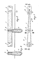
- the guard-rail consists of a series of reinforced concrete elements 1, or optionally light boxes, metal prefabricated elements or vibrated concrete elements, which are filled in situ with concrete or inert material mixtures, each having a fork-shaped end 2 and a pointed end 3.
- Each element 1 is provided, on the middle or center line thereof, with a hole 4 in which is freely seated a vertical pin 5 carried by a concrete pole 6, embedded into the roads surface P so as to allow for the element 1 to rotate (arrows F) as it is impacted.
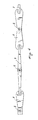
- guard-rail is generally formed by an alternating series of elements 7 and 8, each of which is also pivoted on a pivot pin 5.
- the elements 7 differ since they have two pointed ends, while the elements 8 differ because they have both their ends in the form of a fork.
- the guard-rail assembly will absorb unelastically the impact energy, that is the impact energy from the right side and the left side, and thus this solution is specifically adapted for arranging the guard-rail at the center line of a road having opposite lanes.
Landscapes
- Engineering & Computer Science (AREA)
- Architecture (AREA)
- Civil Engineering (AREA)
- Structural Engineering (AREA)
- Life Sciences & Earth Sciences (AREA)
- Wood Science & Technology (AREA)
- Refuge Islands, Traffic Blockers, Or Guard Fence (AREA)
- Vibration Dampers (AREA)
Applications Claiming Priority (2)
| Application Number | Priority Date | Filing Date | Title |
|---|---|---|---|
| IT2048386 | 1986-05-20 | ||
| IT20483/86A IT1189528B (it) | 1986-05-20 | 1986-05-20 | Guard-rail ad elementi mobili |
Publications (2)
| Publication Number | Publication Date |
|---|---|
| EP0246545A2 true EP0246545A2 (de) | 1987-11-25 |
| EP0246545A3 EP0246545A3 (de) | 1988-08-10 |
Family
ID=11167625
Family Applications (1)
| Application Number | Title | Priority Date | Filing Date |
|---|---|---|---|
| EP87106874A Withdrawn EP0246545A3 (de) | 1986-05-20 | 1987-05-12 | Leitplanke mit beweglichen Elementen |
Country Status (2)
| Country | Link |
|---|---|
| EP (1) | EP0246545A3 (de) |
| IT (1) | IT1189528B (de) |
Cited By (2)
| Publication number | Priority date | Publication date | Assignee | Title |
|---|---|---|---|---|
| US5351791A (en) * | 1990-05-18 | 1994-10-04 | Nachum Rosenzweig | Device and method for absorbing impact energy |
| DE102010037118A1 (de) * | 2010-08-23 | 2012-02-23 | Muhr Und Bender Kg | Schutzplanke für eine Sicherheitseinrichtung an einer Straße und Verfahren zur Herstellung einer Schutzplanke |
Family Cites Families (5)
| Publication number | Priority date | Publication date | Assignee | Title |
|---|---|---|---|---|
| US2927513A (en) * | 1953-06-02 | 1960-03-08 | Dove Harry Ewart | Dividing apparatus for highway lanes and the like |
| DE1534470A1 (de) * | 1964-02-18 | 1969-04-17 | Autostrade Conzessioni E Costr | Leitplanke fuer Autostrassen |
| US3447786A (en) * | 1966-08-20 | 1969-06-03 | Mario Bigni | Road barrier with pivotable span joints |
| DE6919243U (de) * | 1969-06-30 | 1969-10-30 | Friedrich Dipl Ing Stein | Leitschiene fuer autostrassen |
| AT357195B (de) * | 1978-12-15 | 1980-06-25 | Pius Dr Prosenz | Verkehrsleiteinrichtung, verwendbar als mitteltrennung und strassenrandbarriere |
-
1986
- 1986-05-20 IT IT20483/86A patent/IT1189528B/it active
-
1987
- 1987-05-12 EP EP87106874A patent/EP0246545A3/de not_active Withdrawn
Cited By (3)
| Publication number | Priority date | Publication date | Assignee | Title |
|---|---|---|---|---|
| US5351791A (en) * | 1990-05-18 | 1994-10-04 | Nachum Rosenzweig | Device and method for absorbing impact energy |
| DE102010037118A1 (de) * | 2010-08-23 | 2012-02-23 | Muhr Und Bender Kg | Schutzplanke für eine Sicherheitseinrichtung an einer Straße und Verfahren zur Herstellung einer Schutzplanke |
| EP2423385A2 (de) | 2010-08-23 | 2012-02-29 | Muhr und Bender KG | Schutzplanke für eine Sicherheitseinrichtung an einer Straße und Verfahren zur Herstellung einer Schutzplanke |
Also Published As
| Publication number | Publication date |
|---|---|
| IT8620483A0 (it) | 1986-05-20 |
| IT1189528B (it) | 1988-02-04 |
| EP0246545A3 (de) | 1988-08-10 |
| IT8620483A1 (it) | 1987-11-20 |
Similar Documents
| Publication | Publication Date | Title |
|---|---|---|
| US6203242B1 (en) | Crash barrier and barrier elements | |
| EP0079924B1 (de) | Verbesserter betonblock | |
| US5797591A (en) | Guardrail with improved ground anchor assembly | |
| US4186913A (en) | Barrier | |
| CA2007867C (en) | Advanced dynamic impact extension module | |
| PT92221B (pt) | Barreira de proteccao de cabos e processo para a sua montagem | |
| WO1980001292A1 (fr) | Dispositif de guidage du trafic utilisable comme moyen de separation et de bordure de la chaussee | |
| WO2007055792A1 (en) | Cable barrier guardrail system with steel yielding support posts | |
| US4445803A (en) | Resilient marker | |
| US11773549B2 (en) | Roadway safety barrier | |
| CA2634087C (en) | Improved interlocking highway structure | |
| EP1102898A1 (de) | Mittelstreifenleitplanken für kalibrierung von der verzögerung eines aufprallenden fahrzeuges | |
| EP0246545A2 (de) | Leitplanke mit beweglichen Elementen | |
| DE3733846C2 (de) | ||
| DE202005020638U1 (de) | Übergangskonstruktion | |
| DE4420867C2 (de) | Plattenkonstruktion für Fahrbahnen | |
| US20200270831A1 (en) | Energy-absorbing vehicle barrier system | |
| EP0698689A1 (de) | Anti-aufprall Sicherheitseinrichtung, insbesondere für Leitplanken | |
| DE3115300C2 (de) | Schneepflugabweisende Kufe | |
| EP4168629B1 (de) | Durchbruchsichere fahrzeugbarriere | |
| DE2413095C3 (de) | Leiteinrichtung fUr Personen- und Lastkraftwagen | |
| EP0309516A1 (de) | Leitschranke | |
| EP3399104A1 (de) | Schutzbarriere für strassen mit kontrollierter verschiebung | |
| DE102019103444A1 (de) | Rückhalteelement und Rückhaltesystem zur Verkehrssicherung an Verkehrswegen | |
| EP2513376B1 (de) | STRAßENANORDNUNG |
Legal Events
| Date | Code | Title | Description |
|---|---|---|---|
| PUAI | Public reference made under article 153(3) epc to a published international application that has entered the european phase |
Free format text: ORIGINAL CODE: 0009012 |
|
| AK | Designated contracting states |
Kind code of ref document: A2 Designated state(s): AT BE CH DE ES FR GB GR IT LI LU NL SE |
|
| PUAL | Search report despatched |
Free format text: ORIGINAL CODE: 0009013 |
|
| STAA | Information on the status of an ep patent application or granted ep patent |
Free format text: STATUS: THE APPLICATION HAS BEEN WITHDRAWN |
|
| AK | Designated contracting states |
Kind code of ref document: A3 Designated state(s): AT BE CH DE ES FR GB GR IT LI LU NL SE |
|
| 18W | Application withdrawn |
Withdrawal date: 19880805 |
|
| RIN1 | Information on inventor provided before grant (corrected) |
Inventor name: MAGNI, PAOLO |