EP0246488A2 - Apparatus and method for joining veneer strip ends together - Google Patents
Apparatus and method for joining veneer strip ends together Download PDFInfo
- Publication number
- EP0246488A2 EP0246488A2 EP87106511A EP87106511A EP0246488A2 EP 0246488 A2 EP0246488 A2 EP 0246488A2 EP 87106511 A EP87106511 A EP 87106511A EP 87106511 A EP87106511 A EP 87106511A EP 0246488 A2 EP0246488 A2 EP 0246488A2
- Authority
- EP
- European Patent Office
- Prior art keywords
- veneer
- punching
- another
- veneer strip
- adhesive tape
- Prior art date
- Legal status (The legal status is an assumption and is not a legal conclusion. Google has not performed a legal analysis and makes no representation as to the accuracy of the status listed.)
- Granted
Links
Images

Classifications
-
- B—PERFORMING OPERATIONS; TRANSPORTING
- B27—WORKING OR PRESERVING WOOD OR SIMILAR MATERIAL; NAILING OR STAPLING MACHINES IN GENERAL
- B27D—WORKING VENEER OR PLYWOOD
- B27D1/00—Joining wood veneer with any material; Forming articles thereby; Preparatory processing of surfaces to be joined, e.g. scoring
- B27D1/10—Butting blanks of veneer; Joining same along edges; Preparatory processing of edges, e.g. cutting
Definitions
- the invention relates to a device for connecting veneer strip ends according to the preamble of patent claim 1 and a method for connecting veneer strip ends according to the preamble of patent claim 13.
- DE-PS 25 23 203 discloses a punching tool with which complementary tooth profiles are punched on the ends of the veneer strips to be connected.
- This known punching device has a punching knife and a counter knife, the punching tool being rounded off at the base and at the opposite end of its teeth, and the teeth of the punching knife punching out the tooth gaps are wider at corresponding points than the teeth of the counter knife. Due to this intended difference in width and the tip rounding of the teeth, there is air between the punching knife and the counter knife, disadvantageously causing fibers to be drawn into the air gap and blurred punching lines. Another disadvantage is that the retraction of fibers in the counter knife results in high tool wear.
- a disadvantage of this known device is that the calibration gap has to be adjusted by hand each time the type of veneer strip is changed.
- the nominal thicknesses of common veneer strips range between 0.50 mm for walnut and 1.00 mm for spruce in accordance with DIN 4079. According to this DIN 4079, deviations from the specified nominal thicknesses of ⁇ 0.03 mm are permissible. The resulting tolerance range of 0.06 mm makes fine calibration of the calibration shaft indispensable.
- Another disadvantage of the prior art device is that it is not possible to connect veneer strips of small thickness, for example of 0.2 mm, because of the intended mode of operation, since the effectiveness of the device is dependent on a certain longitudinal stability of the veneer strips .
- the invention has for its object to provide a device and a method for connecting veneer strip ends; with or after which a visually closed veneer pattern is quickly and reliably achieved in the connection area.
- this object is achieved on the device side by the features characterized in patent claim 1. On the process side, the features characterized in patent claim 13 are provided to achieve this object.
- Corresponding tooth profile connections which do not have a circumferential gap are produced by the form-fitting punching of intermeshing sharp-edged teeth or tooth gaps provided according to the invention which have fiber-free, straight cutting edges.
- the reworking of the connection point does not lead to an undesired visualization of the funnel strip connection line as in the prior art.
- the corresponding complementary, fluid design of the punching knives means that there is no drawing in of wood fibers. Rather, due to the intended, fluid, fast punching, there is advantageously no tool wear on the counter knife and a self-sharpening effect.
- a major advantage of the unloaded veneer strip guide provided according to the invention is also that small veneer strip thicknesses, such as, for example, noble wood veneers with a thickness of up to 0.2 mm, can be quickly and safely connected to an absolutely closed veneer pattern without, as in the previously known device, transportation problems such veneer strip thicknesses exist.
- small veneer strip thicknesses such as, for example, noble wood veneers with a thickness of up to 0.2 mm
- a certain pressure is required for the complete nesting of the veneer strip ends, which only stronger profiles can tolerate unimpaired in the known design.
- the invention advantageously provides for the veneer strip ends to be pushed into one another at an angle to one another up to the respective geometric tooth profile centers, with the veneer strip ends arranged above these at an angle then applying the adhesive tape from the adhesive tape pliers and then using a powerful hydraulic press stamp together with the interlocking ones Veneer strip ends on the mounting table is pressed evenly.
- the inventive concept of the connection of veneer strip ends also has the advantage over the known device that a much faster procedure can be implemented, since no individual adjustment of the calibration shaft is required, and since the arrangement and function of the adhesive tape pliers provided a comparative due to the elimination of three work cycles Time savings of up to 50% are possible.
- a deflection bead is provided for the veneer between the connection area of the veneers and the respective punching devices, preferably each deflection bead having a deflection surface which extends into the movement path of the veneer end pushed out of the punching device up to approximately half the distance between the punching plane and the Mounting table protrudes.
- the deflection of the veneer stiffeners from the punching plane is advantageously in a range of about 5 to 15%, and a rapid approach with a soft run-out is advantageously provided for pushing the tooth profiles together.
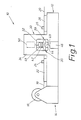
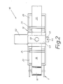
- FIG. 1 An embodiment of a device according to the invention for connecting veneer strip ends is shown schematically in FIG. 1 as a side view and in FIG. 2 as a top view.
- the device 10 has a covered base frame 12, to which a frame arrangement 14 is connected on the left in FIGS. 1 and 2, in which a take-up motor is provided in a manner not shown, which drives a take-up roll 16 in a clock-controlled manner, on which the veneer strips connected to one another Roll form are wound.
- FIG. 1 and 2 show sections of veneer strips 18 and 20 to be connected to one another.
- the end of the veneer strip 18 to be connected to the end of the veneer strip 20 is held on a tensioning slide 22 by means of a clamping element, preferably a clamping strip 24.
- the end of the veneer strip 20 to be connected is held on a tension slide 26 by means of a clamping element, preferably a clamping strip 28.
- the pressure duration of the terminal strips 24 and 28 is determined by the duration of the individual steps for connecting the ends of the veneer strips, the terminal strips 24 and 28 being actuated by control elements (not shown).
- the tensioning slides 22 and 26 each have an exact guide in the base frame 12 and can be moved relative to one another in the course of the connection process by drive elements (not shown).
- Their path of movement is adjustable with an accuracy of a hundredth of a millimeter, and their respective movement sequence has a fast travel section and a slow or creeping travel section in order to push the toothed ends of the veneer strips 18 and 20 into one another in a manner which will be described later.
- the device 10 has a punching and connecting station 30, the essential elements of which are shown schematically in FIG. 1 in a cutout 32 of a covering 34 of the punching and connecting station 30.
- An enlarged schematic representation of the main elements is shown in connection with steps of the connection process in FIGS. 3 to 5.
- the punching and connecting station 30 contains a punching device 36 for the end of the veneer strip 18 and a punching device 38 for the end of the veneer strip 20.
- the punching devices 36 and 38 are from a fastening table 40 arranged centrally between them evenly spaced.
- a fleece pliers 42 are arranged as adhesive tape pliers, which are used to apply an adhesive tape in the form of a non-woven tape 44 from a storage housing 46.
- the adhesive tape can consist of a paper adhesive tape, a transfer glue film on carrier paper or the like instead of a thermally activatable coated nonwoven tape. Only a lower part of the non-woven tape 44 is shown in FIG. 1 in order to be able to show the other elements of the punching and connecting station 30 more clearly.
- a press bar 48 is arranged such that it can be moved vertically and can be acted upon by a hydraulically actuated press ram 50 in a clock-controlled manner, the hydraulic press ram 50 being able to be adjusted transversely to the veneer width in a manner not shown such that it always acts centrally on the press bar 48 .
- the fleece pliers 42 are guided laterally in the punching and connecting station 30 and, prior to the lowering of the press beam 48, can be moved into a housing 52 arranged laterally on the device 10 with drive means, not shown, preferably pneumatic actuating pistons.
- the main components of the punching and connecting station 30 are shown enlarged and schematically in FIG. 3.
- the punching device 36 has a punch knife 54 and a counter knife 56.
- the punching knives have a leading tip and can be positively guided together with their cutting edges.
- the counter knife 56 is arranged stationary in the punching and connecting station 30, while the punch knife 54 can be moved vertically by means of a hydraulic working cylinder 58.
- the punching device 38 has a punch knife 60 and a counter knife 62, the punch knife 60 being vertically movable with the aid of a hydraulic working cylinder 59.
- the hydraulic actuation of the working cylinders 58, 59 is particularly due to the Extremely high and quickly available force, even with strong veneer and with full utilization of the entire width of the device, preferred over slow, limited in performance and expensive to operate pneumatic operation.
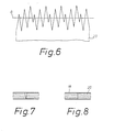
- the punching knives 54 and 60 as well as the counter knives 56 and 62 have a sharp-edged punching profile and have mutually complementary, ie fitting tooth profiles, FIG. 6 showing a preferred tooth profile for a veneer strip end.
- a deflection bead 64 or 66 is integrally formed on the punching knife 54 and on the punching knife 60 in the direction of the fleece pliers 42.
- cooling tubes with air outlet openings are integrated in a manner not shown.
- the deflection beads 64 and 66 approximately halfway between the punching devices 36 and 38 and the center of the fastening table 40, enter the movement paths of the veneer strips 18 and 20, which are predetermined by the punching planes of the punching devices 36 and 38, respectively 66 protrude with their tips from the punching plane in the direction of the plane determined by the upper side of the fastening table 40, whereby they extend approximately up to half the height difference between the punching plane and the fastening plane.
- the deflection beads 64 and 66 have a gradually rounded deflection surface on their respective flanks pointing to the associated punching device 36 and 38, respectively.
- the total height difference between the punching plane and the fastening plane of the fastening stitch 40 is approximately 8 to 10 mm, and the deflection surfaces of the deflection beads 64 and 66 ensure a flat deflection of the respective veneer strip ends advanced from the punching plane with an inclination of approximately 5 to 15%.
- the fleece tongs 42 have rounded lateral deflection surfaces 68 and 70 which merge into one another.
- a pliers mouth is designated, which for gripping the Fleece tape 44 is used.
- the opening and closing movement of the forceps jaw 72 is controlled in such a way that the forceps mouth is first opened to receive one end of the fleece band 44 and then closed, and then after the fleece forceps have moved transversely out of the connection area, the fleece band is released after it has been separated.
- a receiving device 74 is schematically shown above the press beam 48, in which the lower end of a piston rod 76 belonging to the hydraulic press ram 50 engages transversely displaceably.
- the fastening table 40 has approximately the shape of a double-T profile and has a fastening surface 78 and lateral deflection surfaces 80 and 82.
- the deflection surfaces 68 and 70 on the fleece pliers 42 and the deflection surfaces 80 and 82 on the fastening table 40 are inclined outwards and form a funnel-shaped shaft.
- At least the underside of the press beam 48 has a permanent-glue-repellent surface, which is designed as a wear-resistant covering and shows no signs of loosening, bulging and tearing in use.
- Fig. 3 the course of the deflected by the deflection beads 64 and 66 ends of the veneer strips 18 and 20 is indicated, the respective tooth profiles at the ends of the veneer strip ends 18 and 20 with their tips resting on the fastening surface 78 and up to the 6 geometrical centerline shown in Fig. 6 into each other at an obtuse angle are pushed. 4, the fastening area is shown schematically, omitting the punching devices on both sides, in a state in which the fleece band 14 has been loosely placed on the intersecting tooth profiles by the fleece pliers 42 and the fleece pliers 42 have been retracted into the housing 52.
- Fig. 3 the course of the deflected by the deflection beads 64 and 66 ends of the veneer strips 18 and 20 is indicated, the respective tooth profiles at the ends of the veneer strip ends 18 and 20 with their tips resting on the fastening surface 78 and up to the 6 geometrical centerline shown in Fig. 6 into each other at an obtuse angle are pushed. 4, the
- FIG. 5 again shows only a section of the fastening area, with the press beam 48 being lowered from the hydraulic press ram 50 onto the fastening surface 78 of the fastening table 40, the interlocking tooth profiles being pivoted about their geometric center line in a planar engagement and with the superimposed Vleisband is pressed by means of the press beam 48.
- a flatness of the veneer strips is achieved by the pressing action of the hydraulic ram 50, because a central pressure is applied. Tolerances in the veneer strip thicknesses are also compensated for and a high-quality veneer pattern is created, which is also retained during regrinding, pickling and dyeing, as indicated in FIG. 8.
- the inventive design of the method and the device with an unloaded veneer strip guide makes the formation of a calibration shaft superfluous, and it also succeeds in the perfect, high-quality connection of the thinnest veneer strips, for example of fine wood veneers with a thickness of approx. 0.2 mm, with a time saving previously known methods up to 50%.
- the procedure for connecting veneer stiffener ends is as follows. First, the ends of the veneer strips 18 and 20 are clamped into the associated clamping slides 22 and 26 by means of the clamping strips 24 and 28, the clamping slides 22 and 26 being in one another are in the most distant position and the front end of the respective veneer strips lies in the region of the punching device 36 or 38. Then, using an automatic device cycle control, the hydraulic working cylinders 58 and 59 are actuated in order to produce tooth profiles which are complementary to one another at the respective veneer strip ends and which preferably have at least two different long teeth with the same flank angle and in which the tooth height is at least 3 times the tooth base width .
- the tooth profile preferably has the shape shown in FIG. 6 with three teeth of different lengths.
- the tensioning slides 22 and 26 are moved towards one another, with a rapid approach first and then a soft runout being provided in the last phase.
- the respective veneer strip ends are first moved in the punching plane until they meet the deflection beads 64 and 66 and undergo a flat deflection, which leads to an inclination of the order of 5 to 15%.
- the tooth profiles then step onto the fastening surface 78 of the fastening table 40 with the aid of the respective deflecting surfaces 68 and 80 or 70 and 82 and are pushed into one another there at an angle because of the exact respective travel adjustment of the tensioning slides 22 and 26 until the respective geometric ones Center lines G of the tooth profiles coincide.
- the fleece pliers 42 are arranged above the fastening table 40, the end of the fleece band 44 being located in the pliers mouth 72.
- the fleece tongs 42 are activated, the fleece pliers then moving 42 of the fleece band 44 from the storage housing 46 out of the fastening area into the housing 52.
- the press beam 48 is acted upon by the powerful hydraulic press ram 50 in order to press the respective tooth profiles together with the fleece tape 44 placed over them onto the fastening surface 78 of the fastening table 40.
- the underside of the press beam 48 has a permanent glue-repellent coating made of PTFE.
- the duration of action of the hydraulic ram 50 is approximately 1.5 seconds.
- the hydraulic press ram 50 moves back to its starting position after the end of the pressing process.
- the fleece tongs 42 then return to their starting position above the fastening table 40.
- the clamping strips 24 and 28 of the clamping slides 22 and 26 are already raised pneumatically and release the respective veneer strips.
- the tensioning slides 22 and 26 also move away from each other into their outer end position.
- the connected veneer strips are wound up on the take-up roll 16, a suitable control, for example a light barrier, ensuring that the free end of the veneer strip 20 then remains in the area of the punching device 36.
Abstract
Description
Die Erfindung betrifft eine Vorrichtung zum Verbinden von Furnierstreifenenden gemäß dem Oberbegriff des Patentanspruchs 1 sowie ein Verfahren zum Verbinden von Furnierstreifenenden gemäß dem Oberbegriff des Patentanspruchs 13.The invention relates to a device for connecting veneer strip ends according to the preamble of
Seit einigen Jahren besteht in der Möbelindustrie ein wachsender Bedarf an Holzfurnierstreifen. Da derartige Furnierstreifen einzeln durch Schälen, Messern oder Sägen vom Stamm oder Stammteil abgetrennt werden, ist es inzwischen üblich, Einzelfurnierstreifen miteinander zu verbinden und in eine Rollenform zu bringen. Dabei kommt es nicht nur auf einen guten Übergang des Furnierbildes an, sondern auch auf eine dichte und feste Verbindung der einzelnen Furnierstreifen.For some years now, there has been a growing need for wood veneer strips in the furniture industry. Since such veneer strips are separated from the trunk or trunk part individually by peeling, knife or sawing, it is now common practice to connect individual veneer strips to one another and to bring them into a roll shape. It is not only a matter of a good transition of the veneer pattern, but also a tight and firm connection of the individual veneer strips.
In der DE-PS 25 23 203 ist ein Stanzwerkzeug offenbart, mit dem an zu verbindenden Furnierstreifenenden komplementäre Zahnprofile gestanzt werden. Diese vorbekannte Stanzeinrichtung weist ein Stanzmesser und ein Gegemesser auf, wobei das Stanzwerkzeug an der Basis und am entgegengesetzten Ende seiner Zähne abgerundet ist und wobei die die Zahnlücken ausstanzenden Zähne des Stanzmessers an sich entsprechenden Stellen breiter als die Zähne des Gegenmessers sind. Durch diesen vorgesehenen Breitenunterschied und die Spitzenabrundung der Zähne existiert Luft zwischen dem Stanzmesser und dem Gegenmesser, wobei es in nachteiliger Weise zum Einziehen von Fasern in den Luftspalt und zu unscharfen Stanzlinien kommt. Nachteilig ist ferner, daß durch das Einziehen von Fasern beim Gegenmesser ein hoher Werkzeugverschleiß auftritt. Außerdem ist als ungünstig anzusehen, daß durch diese vorbekannte Stanzeinrichtung keine geradlinigen Stanzkanten zu erzielen sind. Hierdurch kommt es im Zahnflankenverbindungsbereich zu einer keilförmigen Naht (siehe Fig. 7), bei der nur eine äußere Kante der Zahnflanken miteinander verbunden ist. Die übliche Nachbearbeitung, bei der durch Schleifen bis zu 40 % der Furnierstärke abgetragen wird, führt dabei zu einem Offenschleifen dieses Keils und damit zu einem unerwünschten Hervorheben der Verbindungsstelle. Beize, Farbe und Lack dringt in die Verbindungsstelle im stärkeren Maße ein, wodurch noch eine stärkere Hervorhebung der Verbindungsstelle hervorgerufen wird.DE-PS 25 23 203 discloses a punching tool with which complementary tooth profiles are punched on the ends of the veneer strips to be connected. This known punching device has a punching knife and a counter knife, the punching tool being rounded off at the base and at the opposite end of its teeth, and the teeth of the punching knife punching out the tooth gaps are wider at corresponding points than the teeth of the counter knife. Due to this intended difference in width and the tip rounding of the teeth, there is air between the punching knife and the counter knife, disadvantageously causing fibers to be drawn into the air gap and blurred punching lines. Another disadvantage is that the retraction of fibers in the counter knife results in high tool wear. In addition, it is to be regarded as unfavorable that no straight-line punched edges can be achieved with this previously known punching device. This results in a wedge-shaped seam in the tooth flank connection area (see FIG. 7), in which only an outer edge of the tooth flanks is connected to one another. The usual post-processing, in which up to 40% of the veneer thickness is removed by sanding, results in this wedge being sanded open and thus in an undesired highlighting of the connection point. Stain, paint and varnish penetrate the connection point to a greater extent, which causes the connection point to be emphasized even more.
Aus dem Prospekt 4/85 der Firma Kuper mit dem Titel "Wie verlängert man Furniere" ist es bereits zum Verbinden von Furnierstreifenenden bekannt, an den zu verbindenden Furnierstreifenenden jeweils aneinanderpassende Zahnprofile mit Zähnen gleicher Länge unter Verwendung der aus der DE-PS 25 23 203 bekannten Stanzeinrichtung zu stanzen, wonach die auf zueinander bewegbaren Spannschlitten ge haltenen Furnierstreifenenden geradlinig in einem Kalibrierschacht ineinanderverschoben werden. Dieser Kalibrierschacht wird mit Hilfe eines Preßbalkens gebildet, der mittels Mikrometerschrauben auf die jeweilige Furnierstärke eingestellt werden muß. Dieser Preßbalken wird nach dem Ineinanderschieben der Furnierstreifen kurzzeitig mit Druck aus einem Pneumatikzylinder zum Richten der Zahnspitzen beaufschlagt. Danach wird der Preßbalken von dem Pneumatikzylinder über einen relativ großen Weg zurückgezogen, um den Zugang für eine Klebebandzange oberhalb des Verbindungsbereichs zu ermöglichen, die dann im nächsten Arbeitsschritt ein Klebeband aufbringt und wieder aus dem Arbeitsbereich des Preßbalkens heraustritt.From brochure 4/85 of the company Kuper with the title "How to extend veneers" it is already known for the connection of veneer strip ends, tooth profiles of the same length that match each other on the veneer strip ends to be connected, using the teeth from DE-PS 25 23 203 to punch known punching device, after which the movable on each other slide ge the veneer strip ends are pushed straight into one another in a calibration shaft. This calibration shaft is formed with the help of a press beam, which must be adjusted to the respective veneer thickness using micrometer screws. After pushing the veneer strips together, this pressure beam is briefly pressurized by a pneumatic cylinder to straighten the tooth tips. Thereafter, the press bar is pulled back from the pneumatic cylinder over a relatively large distance in order to allow access for an adhesive tape pliers above the connection area, which then applies an adhesive tape in the next work step and emerges again from the work area of the press bar.
Als nachteilig ist bei dieser bekannten Vorrichtung anzusehen, daß der Kalibrierspalt bei jedem Wechsel der Furnierstreifenart neu von Hand eingestellt werden muß. Die Nenndicken üblicher Furnierstreifen bewegen sich gemäß der DIN 4079 zwischen 0,50 mm für Nußbaum und 1,00 mm für Fichte. Gemäß dieser DIN 4079 sind Abweichungen der angegebenen Nenndicken von ±0,03 mm zulässig. Der hieraus resultierende Toleranzbereich von 0,06 mm macht ein Feinkalibrieren des Kalibrierschachts unerläßlich.A disadvantage of this known device is that the calibration gap has to be adjusted by hand each time the type of veneer strip is changed. The nominal thicknesses of common veneer strips range between 0.50 mm for walnut and 1.00 mm for spruce in accordance with DIN 4079. According to this DIN 4079, deviations from the specified nominal thicknesses of ± 0.03 mm are permissible. The resulting tolerance range of 0.06 mm makes fine calibration of the calibration shaft indispensable.
Beim Betreib der vorbekannten Vorrichtung besteht auch die Gefahr der Überlappung der Furnierstreifenenden im Kalibrierschacht. Nachteilig ist ferner, daß die Arbeitsfläche des Preßbalkens verschleißende Beläge aufweist, die zum Lösen, Bauchen und Aufreißen neigen. Ferner kommt es bei dieser Vorrichtung zu einem ungleichmäßigen Beaufschlagen der Verbindungsstelle, da der bzw. die Preßzylinder gegen die Wirkung der Mikrometerschrauben starr und außerhalb der Mitte der Furnierstreifen, die je nach Furnierbeschaffenheit unterschiedlich breit sein können, am Preßbalken angreifen.When operating the known device, there is also a risk of the veneer strip ends overlapping in the calibration shaft. Another disadvantage is that the working surface of the press beam has wear-resistant coverings that tend to loosen, bulge and tear. Furthermore, in this device there is an uneven loading of the connection point, since the press cylinder or cylinders press against the action of the micrometer screws rigidly and outside the center of the veneer strips, which can vary in width depending on the veneer properties, on the press beam.
Dies ist besonders bei unterschiedlichen Furnierstärken im üblichen Toleranzbereich problematisch, da hierdurch die beiderseitigen Zähne der Furnierstreifenenden keine absolute Planlage miteinander erreichen. Zu der ungünstigen ungleichmäßigen Beaufschlagung des Preßbalkens tritt der weitere Nachteil, daß die Druckleistung des Pneumatikzylinders unzureichend ist und wegen der konzeptionsbedingten langen Schiebewege beim pneumatischen Betrieb hohe Energiekosten anfallen.This is particularly problematic in the case of different veneer thicknesses in the usual tolerance range, since as a result the teeth on both sides of the veneer strip ends do not achieve absolute flatness with one another. In addition to the unfavorable uneven loading of the press beam, there is the further disadvantage that the pressure output of the pneumatic cylinder is inadequate and high energy costs are incurred in pneumatic operation because of the design-related long sliding paths.
Ein weiterer Nachteil ist bei der vor bekannten Vorrichtung, darin zu sehen, daß auf Grund der vorgesehenen Funktionsweise keine Verbindung von Funierstreifen geringer Stärke, beispielsweise von 0,2 mm, möglich ist, da die Wirksamkeit der Vorrichtung von einer gewissen Längsstabilität der Furnierstreifen abhängig ist.Another disadvantage of the prior art device is that it is not possible to connect veneer strips of small thickness, for example of 0.2 mm, because of the intended mode of operation, since the effectiveness of the device is dependent on a certain longitudinal stability of the veneer strips .
Der Erfindung liegt die Aufgabe zugrunde, eine Vorrichtung und ein Verfahren zum Verbinden von Furnierstreifenenden verfügbar zu machen; mit der bzw. nach dem schnell und sicher ein visuell geschlossenes Furnierbild im Verbindungsbereich erzielt wird.The invention has for its object to provide a device and a method for connecting veneer strip ends; with or after which a visually closed veneer pattern is quickly and reliably achieved in the connection area.
Erfindungsgemäß wird diese Aufgabe vorrichtungsseitig durch die im Patentanspruch 1 gekennzeichneten Merkmale gelöst. Verfahrensseitig sind zur Lösung dieser Aufgabe die im Patentanspruch 13 gekennzeichneten Merkmale vorgesehen.According to the invention, this object is achieved on the device side by the features characterized in
Bevorzugte Weiterbildungen der Vorrichtung und des Verfahrens sind in den jeweils nachgeordneten Patentansprüchen enthalten.Preferred developments of the device and the method are contained in the respective subordinate claims.
Durch das erfindungsgemäß vorgesehene formschlüssige Stanzen von ineinanderpassenden scharfkantigen Zähnen bzw. Zahnlücken werden entsprechende Zahnprofilverbindungen hergestellt, die keinen umlaufenden Spalt aufweisen und die faserfreie geradlinig verlaufende Stanzkanten besitzen. Hierdurch kommt es bei einer nachschleifenden Behandlung der Verbindungsstelle nicht zu einer unerwünschten Sichtbarmachung der Funierstreifenverbindungslinie wie beim Stand der Technik. Hinzu kommt der Vorteil, daß durch die entsprechende komplementäre formflüssige Ausbildung der Stanzmesser kein Einziehen von Holzfasern auftritt. Vielmehr kommt es auf Grund des vorgesehenen formflüssigen schnellen Stanzens vorteilhaft zur Vermeidung des Werkzeugverschleißes des Gegenmessers und zu einem Selbstschärfeffekt.Corresponding tooth profile connections which do not have a circumferential gap are produced by the form-fitting punching of intermeshing sharp-edged teeth or tooth gaps provided according to the invention which have fiber-free, straight cutting edges. As a result, the reworking of the connection point does not lead to an undesired visualization of the funnel strip connection line as in the prior art. In addition, there is the advantage that the corresponding complementary, fluid design of the punching knives means that there is no drawing in of wood fibers. Rather, due to the intended, fluid, fast punching, there is advantageously no tool wear on the counter knife and a self-sharpening effect.
Von Vorteil ist auch die Ausbildung der Klebebandzange mit der seitliche Ablenkflächen aufweisenden Unterseite, da hierdurch die Klebebandzange selbst auch die Aufgabe eines Führungselements für die erfindungsgemäß vorgesehene freie unbelastete Furnierstreifenführung übernimmt. Mit dieser Funktionszuweisung für die Klebebandzange wird vorteilhaft zusammen mit dem versetzt zur Stanzebene unterhalb der Klebebandzange der angeordneten Befestigungstisch ein Einführungsbereich für das gegenseitig Ineinanderschieben der Furnierstreifenenden geschaffen, der im Unterscheid zu einem Kalibrierschacht keiner exakten Kalibrierung bezüglich der jeweils verwendeten Furnierstreifenstärke bedarf. Vorteilhaft wird dieses freie Ineinanderschieben der Furnierstreifenenden unter einem Winkel bis zur geometrischen Mittelachse unter Verwendung einer exakten Führung und Einstellung der Bewegungsbereiche der beiden Spannschlitten vorgenommen.Also of advantage is the formation of the adhesive tape pliers with the underside having side deflecting surfaces, since in this way the adhesive tape pliers themselves also assume the function of a guide element for the free, unloaded veneer strip guide provided according to the invention. This function assignment for the tape pliers, together with the fastening table arranged below the tape pliers below the tape pliers, advantageously creates an insertion area for pushing the veneer strip ends into each other, which, in contrast to a calibration shaft, does not require exact calibration with regard to the veneer strip thickness used in each case. This free pushing together of the veneer strip ends is advantageously carried out at an angle to the geometric central axis using exact guidance and adjustment of the movement ranges of the two tensioning slides.
Zu dem vorteilhaften Qualitätsgewinn der Furnierstreifenverbindung mit einer formflüssigen, weitgehend faserfreien Herstellung eines bedarfsgerechten Zahnprofils kommt auf Grund der Verwendung des hydraulischen Preßstempels auch der Qualitätsvorteil, daß die Furnierstreifen durch zentrische, d.h. im Bereich der Mitte der Furnierstreifenbreite erfolgende Druckbeaufschlagung kein dickenmäßiges Versetzt sein auf Grund der Toleranz von Furnierstreifen aufweisen, sondern eine Planlage der Furnierstreifen gewährleistet ist.In addition to the advantageous increase in quality of the veneer strip connection with a fluid, largely fiber-free production of a needs-based tooth profile due to the use of the hydraulic press ram, there is also the quality advantage that the veneer strips are not offset in terms of thickness by centric pressure application, ie in the area of the center of the veneer strip width be due to the tolerance of veneer strips, but a flatness of the veneer strips is guaranteed.
Ein wesentlicher Vorteil der erfindungsgemäßen vorgesehenen unbelasteten Furnierstreifenführung besteht auch darin, daß kleine Furnierstreifendicken, wie beispielsweise Edelholzfurniere mit einer Stärke bis 0,2 mm, einwandfrei schnell und sicher mit einem absolut geschlossenen Furnierbild verbunden werden können, ohne daß wie bei der vorbekannten Vorrichtung Transportprobleme bei derartigen Furnierstreifendicken bestehen. Bei der vorbekannten Vorrichtung ist für das vollständige Ineinanderschieben der Furnierstreifenenden ein gewisser Druck erforderlich, den bei der vorbekannten Konzeption nur stärkere Profile unbeeinträchtigt vertragen können.A major advantage of the unloaded veneer strip guide provided according to the invention is also that small veneer strip thicknesses, such as, for example, noble wood veneers with a thickness of up to 0.2 mm, can be quickly and safely connected to an absolutely closed veneer pattern without, as in the previously known device, transportation problems such veneer strip thicknesses exist. In the known device, a certain pressure is required for the complete nesting of the veneer strip ends, which only stronger profiles can tolerate unimpaired in the known design.
Demgegenüber ist bei der Erfindung in günstiger Weise ein Ineinanderschieben der Furnierstreifenenden unter einem Winkel zueinander bis zu den jeweiligen geometrischen Zahnprofilmitten vorgesehen, wobei dann das über diesen im Winkel angeordneten Furnierstreifenenden das Klebeband von der Klebebandzange aufgelegt und anschliessend durch einen leistungsstarken hydraulischen Preßstempel gemeinsam mit den ineinandergreifenden Furnierstreifenenden auf dem Befestigungstisch gleichmäßig gepreßt wird. Die erfindungsgemäße Konzeption der Verbindung von Furnierstreifenenden hat gegenüber der vorbekannten Vorrichtung auch den Vorteil, daß ein wesentlich schnellerer Verfahrensablauf realisierbar ist, da keine individuelle Einstellung des Kalibrierschachts erforderlich ist und da durch die vorgesehene Anordnung und Funktion der Klebebandzange aufgrund des Wegfalls von drei Arbeitstakten eine vergleichsweise Zeitersparnis von bis zu 50 % möglich ist.In contrast, the invention advantageously provides for the veneer strip ends to be pushed into one another at an angle to one another up to the respective geometric tooth profile centers, with the veneer strip ends arranged above these at an angle then applying the adhesive tape from the adhesive tape pliers and then using a powerful hydraulic press stamp together with the interlocking ones Veneer strip ends on the mounting table is pressed evenly. The inventive concept of the connection of veneer strip ends also has the advantage over the known device that a much faster procedure can be implemented, since no individual adjustment of the calibration shaft is required, and since the arrangement and function of the adhesive tape pliers provided a comparative due to the elimination of three work cycles Time savings of up to 50% are possible.
Gemäß einer bevorzugten Weiterbildung ist zwischen dem Verbindungsbereich der Furnierenden und den jeweiligen Stanzeinrichtungen jeweils ein Ablenkungswulst für das Furnierende vorgesehen, wobei bevorzugt jederAblenkungswulst eine Ablenkungsfläche aufweist, die in die Bewegungsbahn des aus der Stanzeinrichtung vorgeschobenen Furnierendes bis etwa zur Hälfte des Abstandes zwischen der Stanzebene und dem Befestigungstisch ragt. Die Ablenkung der Furniersteifen aus der Stanzebene liegt vorteilhaft etwa in einem Bereich von 5 bis 15 %, und für das Ineinanderschieben der Zahnprofile ist vorteilhaft eine schnelle Annäherung mit einem weichen Auslaufen vorgesehen.According to a preferred development, a deflection bead is provided for the veneer between the connection area of the veneers and the respective punching devices, preferably each deflection bead having a deflection surface which extends into the movement path of the veneer end pushed out of the punching device up to approximately half the distance between the punching plane and the Mounting table protrudes. The deflection of the veneer stiffeners from the punching plane is advantageously in a range of about 5 to 15%, and a rapid approach with a soft run-out is advantageously provided for pushing the tooth profiles together.
Das schnell und formschlüssig gestanzte Zahnprofil hat eine bedarfsgerechte Form und besteht bevorzugt aus wenigstens zwei unterschiedlich langen Zähnen mit gleichen Flankenwinkeln, wobei die Zahnlänge mindestens das 3-Fache der Zahnfußbreite beträgt. Zur sicheren Verbindung der Furnierstreifen ist weiterhin eine Feuchtigkeits- und Temperatursteuerung von Vorteil. Gemäß einer bevorzugten Weiterbildung der Erfindung ist daher der Ablenkungswulst als Kühleinrichtung mit Luftaustrittsöffnungen ausgebildet. Vorzugsweise ist die Klebebandzange als Vlieszange für ein Klebeband in Form eines Verleimungsvlies ausgebildet. Weitere Einzelheiten, Merkmale und Vorteile der Erfindung sind dem anschliessenden Beschreibungsteil zu entnehmen, in dem ein Ausführungsbeispiel der Erfindung unter Bezugnahme auf die beigefügten Zeichnungen näher erläutert wird. Es zeigen:
- Fig. 1 eine schematische Seitenansicht eines Ausführungsbeispiels einer erfindungsgemäßen Vorrichtung zum Verbinden von Furnierstreifenenden;
- Fig. 2 eine Draufsicht auf die Vorrichtung von Fig. 1;
- Fig. 3 eine schematische Darstellung der Funktionselemente in der Umgebung des Verbindungsbereichs, wobei die Funierstreifenenden von beiden Seiten auf dem Befestigungstisch im Winkel ineinandergeschoben sind;
- Fig. 4 eine schematische Darstellung der auf dem Befestigungstisch ineinandergeschobenen Furnierstreifenenden mit über diesen aufgebrachtem Verleimungsvlies, wobei die Vlieszange aus dem Arbeitsbereich des Preßstempels herausbewegt worden ist;
- Fig. 5 die abschließende Phase bei der Verbindung der Furnierstreifenenden, in der der Preßstempel das Verleimungsvlies gemeinsam mit den ineinandergreifenden Furnierstreifenenden auf den Befestigungstisch preßt;
- Fig. 6 eine Draufsicht auf eine bevorzugte Zahnform für ein Furnierstreifenende;
- Fig. 7 einen Schnitt durch eine Verbindungsnaht zwischen zwei Zahnflanken einer Furnierstreifenverbindung, die mit einer Vorrichtung gemäß dem Stand der Technik hergestellt worden ist; und
- Fig. 8 einen Schnitt durch die Verbindungsstelle zwischen zwei Zahnflanken einer Furnierstreifenverbindung, die erfindungsgemäß hergestellt worden ist.
- Figure 1 is a schematic side view of an embodiment of a device according to the invention for connecting veneer strip ends.
- Fig. 2 is a top view of the device of Fig. 1;
- Fig. 3 is a schematic representation of the functional elements in the vicinity of the connection area, the funnel strip ends being pushed into one another on both sides of the fastening table;
- 4 shows a schematic illustration of the veneer strip ends pushed into one another on the fastening table with the gluing fleece applied over them, the fleece pliers having been moved out of the working area of the press ram;
- 5 shows the final phase in the connection of the veneer strip ends, in which the press ram presses the gluing fleece together with the interlocking veneer strip ends onto the fastening table;
- 6 shows a plan view of a preferred tooth shape for a veneer strip end;
- 7 shows a section through a connecting seam between two tooth flanks of a veneer strip connection which has been produced using a device according to the prior art; and
- 8 shows a section through the connection point between two tooth flanks of a veneer strip connection which has been produced according to the invention.
Ein Ausführungsbeispiel einer erfindungsgemäßen Vorrichtung zum Verbinden von Furnierstreifenenden ist schematisiert in Fig. 1 als Seitenansicht und in Fig. 2 als Draufsicht dargestellt. Die Vorrichtung 10 besitzt ein verkleidetes Grundgestell 12, an das sich in den Fig. 1 und 2 linksseitig eine Rahmenanordnung 14 anschließt, in der in nicht dargestellter Weise ein Aufwickelmotor vorgesehen ist, der eine Aufwickelrolle 16 taktgesteuert antreibt, auf der die miteinander verbundenen Furnierstreifen in Rollenform aufgewickelt werden.An embodiment of a device according to the invention for connecting veneer strip ends is shown schematically in FIG. 1 as a side view and in FIG. 2 as a top view. The
In den Fig. 1 und 2 sind Abschnitte von miteinander zu verbindenden Furnierstreifen 18 und 20 dargestellt. Das mit dem Ende des Furnierstreifens 20 zu verbindende Ende des Furnierstreifens 18 ist auf einem Spannschlitten 22 mittels eines Klemmelements, vorzugsweise einer Klemmleiste 24 gehalten. Das zu verbindende Ende des Furnierstreifens 20 ist auf einem Spannschlitten 26 mittels eines Klemmelements, vorzugsweise einer Klemmleiste 28 gehalten. Die Andruckdauer der Klemmleisten 24 und 28 wird durch die Dauer der einzelnen Schritte zum Verbinden der Furnierstreifenenden bestimmt, wobei die Klemmleisten 24 und 28 durch nicht dargestellte Steuerorgane betätigt werden. Die Spannschlitten 22 und 26 weisen jeweils eine exakte Führung in dem Grundgestell 12 auf und sind im Rahmen des Verbindungsvorgangs durch nicht dargestellte Antriebsorgane zueinander bewegbar. Ihr Bewegungsweg ist mit einer Genauigkeit von einem hundertstel Millimeter einstellbar, und ihr jeweiliger Bewegungsablauf weist einen Schnellfahrabschnitt und einen Schon- bzw. Kriechfahrabschnitt auf, um die verzahnten Enden der Furnierstreifen 18 und 20 in einer Weise ineinander zu schieben, die später noch beschrieben wird.1 and 2 show sections of veneer strips 18 and 20 to be connected to one another. The end of the
Die Vorrichtung 10 weist eine Stanz- und Verbindungsstation 30 auf, deren wesentliche Elemente schematisiert in Fig. 1 in einem Ausschnitt 32 einer Verkleidung 34 der Stanz- und Verbindungsstation 30 dargestellt sind. Eine vergrößerte schematisierte Darstellung der Hauptelemente ist im Zusammenhang mit Schritten des Verbinddungsvorgangs in den Fig. 3 bis 5 dargestellt.The
Die Stanz- und Verbindungsstation 30 enthält eine Stanzeinrichtung 36 für das Ende des Furnierstreifens 18 und eine Stanzeinrichtung 38 für das Ende des Furnierstreifens 20. Die Stanzeinrichtungen 36 und 38 sind von einem mittig zwischen diesen angeordneten Befestigungstisch 40 gleichmäßig beabstandet. Oberhabt des Befestigungstisches 40 ist als Klebebandzange eine Vlieszange 42 angeordnet, die zum Aufbringen eines Klebebandes in Form eines Vliesbandes 44 aus einem Vorratsgehäuse 46 dient. Das Klebeband kann statt aus einem thermisch aktivierbar beschichteten Vliesband aus einem Papierklebeband, einem Übertragungsleimfilm auf Trägerpapier oder dergleichen bestehen. Von dem Vliesband 44 ist in Fig. 1 nur ein unterer Teil dargestellt, um die übrigen Elemente der Stanz- und Verbindungsstation 30 deutlicher darstellen zu können. Oberhalb der Vlieszange 42 ist ein Preßbalken 48 vertikal bewegbar geführt angeordnet, der von einem hydraulisch betätigten Preßstempel 50 taktgesteuert beaufschlagbar ist, wobei der hydraulische Preßstempel 50 quer zur Furnierbreite in nicht dargestellter Weise so verstellt werden kann, daß er stets mittig an dem Preßbalken 48 angreift. Die Vlieszange 42 ist in der Stanz- und Verbindungsstation 30 seitlich geführt und vor dem Absenken des Preßbalkens 48 in ein seitlich an der Vorrichtung 10 angeordnetes Gehäuse 52 mit nicht dargestellten Antriebsmitteln, vorzugsweise pneumatischen Stellkolben, bewegbar.The punching and connecting
Die Hauptbestandteile der Stanz- und Verbindungsstation 30 sind in der Fig. 3 vergrößert und schematisiert dargestellt. Die Stanzeinrichtung 36 weist ein Stanzmesser 54 und ein Gegenmesser 56 auf. Die Stanzmesser besitzen eine voreilende Spitze und sind mit ihren Schneidkanten formschlüssig aneinandervorbeiführbar. Das Gegenmeser 56 ist ortsfest in der Stanz- und Verbindungsstation 30 angeordnet, während das Stanzmesser 54 mittels eines hydraulischen Arbeitszylinders 58 vertikal bewegbar ist. In gleicher Weise besitzt die Stanzeinrichtung 38 ein Stanzmesser 60 und ein Gegenmeser 62, wobei das Stanzmesser 60 mit Hilfe eines hydraulischen Arbeitszylinders 59 vertikal bewegbar ist. Die hydraulische Betätigung der Arbeitszylinder 58, 59 wird insbesondere wegen der äußerst hohen und schnell verfügbaren Kraft auch bei starkem Furnier und bei voller Ausnutzung der gesamten Breite der Vorrichtung gegenüber der langsamen, in der Leistung begrenten und im Betrieb kostspieligen pneumatischen Betätigung bevorzugt. Die Stanzmesser 54 und 60 sowie die Gegenmesser 56 und 62 haben ein scharfkantiges Stanzprofil und weisen zueinander komplementäre, d.h. ineinander passende Zahnprofile auf, wobei Fig. 6 ein bevorzugtes Zahnprofil für ein Furnierstreifenende zeigt.The main components of the punching and connecting
Auf Grund der formschlüssigen Ausbildung der jeweiligen Stanzmesser und Gegenmesser existiert zwischen ihnen beim Stanzvorgang keine Luft, und es kommt nicht zu einem Einziehen von Holzfasern in den Spalt und damit zu einem Verschleißen der Gegenmesser. Vielmehr hat die jeweilige komplementäre formschlüssige Ausbildung der Messer einen selbstschärfenden Effekt.Due to the form-fitting design of the respective punching knife and counter knife, there is no air between them during the punching process, and there is no drawing of wood fibers into the gap and thus wear of the counter knife. Rather, the respective complementary form-fitting design of the knives has a self-sharpening effect.
An dem Stanzmesser 54 und an dem Stanzmesser 60 ist jeweils in Richtung auf die Vlieszange 42 einstückig ein Ablenkungswulst 64 bzw. 66 angeformt. In den Ablenkungswülsten 64 und 66 sind in nicht dargestellter Weise Kühlrohre mit Luftaustrittsöffnungen integriert. Die Ablenkungswülste 64 bzw. 66 treten etwa auf der Hälfte des Weges zwischen den Stanzeinrichtungen 36 bzw. 38 und der Mitte des Befestigungstisches 40 in die durch die Stanzebenen der Stanzeinrichtungen 36 bzw. 38 vorgegebenen Bewegungsbahnen der Furnierstreifen 18 bzw. 20. Die Ablenkungswülste 64 bzw. 66 ragen mit ihren Kuppen aus der Stanzebene in Richtung auf die durch die Oberseite des Befestigungstischs 40 bestimmte Ebene, wobei sie sich etwa bis zur Hälfte der Höhendifferenz zwischen der Stanzebene und der Befestigungsebene erstrecken. Die Ablenkungswülste 64 und 66 besitzen an ihrer jeweils auf die zugeordnete Stanzeinrichtung 36 bzw. 38 weisenden Flanke eine allmählich gerundete Ablenkungsfläche auf. Die gesamte Höhendifferenz zwischen der Stanzebene und der Befestigungsebene des Befestigungstiches 40 beträgt etwa 8 bis 10 mm, und die Ablenkungsflächen der Ablenkungswülste 64 bzw. 66 sorgen für eine flache Umlenkung der jeweiligen vorgeschobenen Furnierstreifenenden aus der Stanzebene mit einer Neigung von etwa 5 bis 15 %.A
Die Vlieszange 42 weist gerundete seitliche Ablenkflächen 68 und 70 auf, die ineinander übergehen. Mit 72 ist ein Zangenmaul bezeichnet, das zum Ergreifen des Vliesbandes 44 dient. Die Öffnungs- und Schließbewegung des Zangenmauls 72 wird derart gesteuert, daß das Zangenmaul zunächst zur Aufnahme eines Endes des Vliesbandes 44 geöffnet und dann geschlossen wird und dann nach der Querbewegung der Vlieszange aus dem Verbindungsbereich heraus das Vliesband nach dessen Abtrennen freigibt.The fleece tongs 42 have rounded lateral deflection surfaces 68 and 70 which merge into one another. With 72 a pliers mouth is designated, which for gripping the
In Fig. 3 ist oberhalb des Preßbalkens 48 eine Aufnahmeeinrichtung 74 schematisch dargestellt, in die das untere Ende einer zu dem hydraulischen Preßstempel 50 gehörenden Kolbenstange 76 quer verschiebbar eingreift. Hierdurch kann bei der Verschiebung des hydraulischen Preßstempels 50 stets ein mittiger Angriff an den Preßbalken 48 erreicht werden, um über den Preßbalken 48 einen gleichmäßigen Druck auf die Befestigungsfläche des Befestigungstisches 40 auszuüben.In Fig. 3, a receiving
Der Befestigungstisch 40 hat in etwa die Form eines Doppel-T-Profils und besitzt eine Befestigungsfläche 78 sowie seitliche Ablenkflächen 80 und 82. Die Ablenkflächen 68 und 70 an der Vlieszange 42 und die Ablenkflächen 80 und 82 an dem Befestigungstisch 40 sind nach außen geneigt und bilden einen trichterförmigen Schacht. Wenigstens die Unterseite des Preßbalkens 48 besitzt eine dauerleimabweisende Fläche, die als verschleißfester Belag ausgebildet ist und weder Lösungs- noch Ausbeul- und Aufreißerscheinungen im Einsatz zeigt.The fastening table 40 has approximately the shape of a double-T profile and has a
In Fig. 3 ist der Bahnverlauf der von den Ablenkungswülsten 64 bzw. 66 abgelenkten Enden der Furnierstreifen 18 bzw. 20 angedeutet, wobei die jeweiligen Zahnprofile an den Enden der Furnierstreifenenden 18 bzw. 20 mit ihren Spitzen auf der Befestigungsfläche 78 aufliegen und bis zu der in Fig. 6 dargestellten geometrischen Mittellinie unter einem stumpfen Winkel ineinanderge schoben sind. In Fig. 4 ist der Befestigungsbereich unter Weglassung der beiderseitigen Stanzeinrichtungen schematisch in einem Zustand gezeigt, in dem das Vliesband 14 lose von der Vlieszange 42 auf die sich kreuzenden Zahnprofile aufgelegt worden ist und die Vlieszange 42 in das Gehäuse 52 zurückgezogen ist. Fig. 5 zeigt wiederum nur einen Ausschnitt aus dem Befestigungsbereich, wobei der Preßbalken 48 von dem hydraulischen Preßstempel 50 auf die Befestigungsfläche 78 des Befestigungstisches 40 abgesenkt ist, wobei die ineinandergreifenden Zahnprofile um ihre geometrische Mittellinie in einen planen Eingriff verschwenkt werden und wobei das aufliegende Vleisband mittels des Preßbalkens 48 aufgepreßt ist. Dabei wird durch die Preßwirkung des hydraulischen Preßstempels 50 eine Planlage der Furnierstreifen erreicht, weil eine zentrische Druckbeaufschlagung erfolgt. Dabei werden auch Toleranzen in den Furnierstreifendicken ausgeglichen und es entsteht ein qualitativ hochwertiges Furnierbild, das auch beim Nachschleifen, Beizen und Färben erhalten bleibt, wie in Fig. 8 angedeutet.In Fig. 3 the course of the deflected by the
Durch die erfindungsgemäße Ausbildung des Verfahrens und der Vorrichtung mit einer unbelasteten Furnierstreifenführung wird die Ausbildung eines Kalibrierschachts überflüssig, und es gelingt auch die einwandfreie qualitativ hochwertige Verbindung dünnster Furnierstreifen, beispielsweise von Edelholzfurnieren mit einer Stärke von ca. 0,2 mm, mit einer Zeitersparnis gegenüber vorbekannten Verfahren bis zu 50 %.The inventive design of the method and the device with an unloaded veneer strip guide makes the formation of a calibration shaft superfluous, and it also succeeds in the perfect, high-quality connection of the thinnest veneer strips, for example of fine wood veneers with a thickness of approx. 0.2 mm, with a time saving previously known methods up to 50%.
Das Verfahren zum Verbinden von Furniersteifenenden läuft folgendermaßen ab. Zunächst werden die Enden der Furnierstreifen 18 und 20 in die zugeordneten Spannschlitten 22 bzw. 26 mittels der Klemmleisten 24 bzw. 28 eingespannt, wobei sich die Spannschlitten 22 und 26 in ihrer voneinan der einferntesten Stellung befinden und wobei das vordere Ende der jeweiligen Furnierstreifen im Bereich der Stanzeinrichtung 36 bzw. 38 liegt. Anschließend erfolgt unter Verwendung einer automatischen Vorrichtungstaktsteuerung eine Betätigung der hydraulischen Arbeitszylinder 58 und 59, um bei den jeweiligen Furnierstreifenenden zueinander komplementäre Zahnprofile herzustellen, die vorzugsweise wenigstens zwei unterschiedliche lange Zähne mit gleichem Flankenwinkel aufweisen und bei denen die Zahnhöhe mindestens das 3-Fache der Zahnfußbreite beträgt. Vorzugsweise hat das Zahnprofil die in Fig. 6 dargestellte Form mit drei unterschiedlich langen Zähnen.The procedure for connecting veneer stiffener ends is as follows. First, the ends of the veneer strips 18 and 20 are clamped into the associated clamping slides 22 and 26 by means of the clamping strips 24 and 28, the clamping slides 22 and 26 being in one another are in the most distant position and the front end of the respective veneer strips lies in the region of the
Nach dem Stanzen der jeweiligen Zahnprofile werden die Spannschlitten 22 und 26 aufeinander zu bewegt, wobei zunächst eine schnelle Annäherung und dann in der letzten Phase ein weiches Auslaufen vorgesehen ist. Bei dieser Bewegung der Spannschlitten werden die jeweiligen Furnierstreifenenden zunächst in der Stanzebene bewegt, bis sie auf die Ablenkungswulste 64 bzw. 66 treffen und von diesen eine flache Umlenkung erfahren, die zu einer Neigung in der Größenordnung von 5 bis 15 % führt. Die Zahnprofile treten dann unter Zurhilfenahme der jeweiligen Ablenkflächen 68 und 80 bzw. 70 und 82 auf die Befestigungsfläche 78 des Befestigungstischs 40 und werden dort auf Grund der genauen jeweiligen Wegeinstellung der Spannschlitten 22 bzw. 26 unter einem Winkel so weit ineinandergeschoben, bis die jeweiligen geometrischen Mittellinien G der Zahnprofile zusammenfallen. Während dieses Ineinanderschiebens ist die Vlieszange 42 oberhalb des Befestigungstischs 40 angeordnet, wobei sich das Ende des Vliesbandes 44 in dem Zangenmaul 72 befindet.After the respective tooth profiles have been punched, the tensioning slides 22 and 26 are moved towards one another, with a rapid approach first and then a soft runout being provided in the last phase. During this movement of the tensioning slides, the respective veneer strip ends are first moved in the punching plane until they meet the
Sobald die Spannschlitten 22 und 26 ihre Endstellung erreicht haben, erfolgt eine Ansteuerung der Vlieszange 42, wobei sich die Vlieszange unter 42 Mitnahme des Vliesbandes 44 aus dem Vorratsgehäuse 46 dann aus dem Befestigungsbereich in das Gehäuse 52 bewegt. Unmittelbar darauf erfolgt dann die Beaufschlagung des Preßbalkens 48 durch den kräftigen hydraulischen Preßstempel 50, um die jeweiligen Zahnprofile zusammen mit dem darüber abgelegten Vliesband 44 auf der Befestigungsfläche 78 des Befestigungstischs 40 zu verpressen. Die Unterseite des Preßbalkens 48 weist dabei eine dauerleimabweisende Beschichtung aus PTFE auf. Die Einwirkungsdauer des hydraulischen Preßstempels 50 beträgt etwa 1,5 Sekunden.As soon as the tensioning slides 22 and 26 have reached their end position, the fleece tongs 42 are activated, the fleece pliers then moving 42 of the
Der hydraulische Preßstempel 50 fährt nach dem Ende des Preßvorgangs in seine Ausgangsstellung zurück. Die Vlieszange 42 nimmt dann wieder ihre Ausgangsstellung oberhalb des Befestigungstisches 40 ein. Während dieses Arbeitsschrittes sind bereits die Klemmleisten 24 bzw. 28 der Spannschlitten 22 bzw. 26 pneumatisch angehoben und geben die jeweiligen Furnierstreifen frei. Gleichzeitig bewegen sich auch die Spannschlitten 22 bzw. 26 voneinander weg jeweils in ihre aüßere Endstellung. Während dieses Bewegungsvorgangs erfolgt ein Aufwickeln der verbundenen Furnierstreifen auf der Aufwickelrolle 16, wobei durch eine geeignete Kontrolle, beispielsweise eine Lichtschranke, sichergestellt ist, daß das freie Ende des Furnierstreifens 20 dann im Bereich der Stanzeinrichtung 36 bleibt. Nach Zuführung eines neuen Furnierstreifens in den Bereich der Stanzeinrichtung 34 und dem Festspannen der Streifen durch die Klemmleisten 24 bzw. 28 wiederholt sich der zuvor beschriebene Vorgang automatisch unter Zuhilfenahme einer entsprechenden Taktsteuerung.The
Claims (17)
Stanzeinrichtungen (36,38) für die Herstellung von jeweils ineinander passenden Zahnprofilen an den Enden von Furnierstreifen (18,20) zwei zueinander bewegbaren Spannschlitten (22, 24) für das Halten und Ineinanderschieben der Furnierstreifenenden,
einer Klebebandzange ( 42) zum Aufbringen eines Klebebands (44), und aus
einem Preßstempel (50) für den Verbindungsbereich der Furnierstreifenenden,
dadurch gekennzeichnet,
daß jede Stanzeinrichtung (36, 38) ein Stanzmesser (54, 60) und ein Gegenmesser (56, 62) mit jeweils formschlüssig ineinander passenden scharfkantigen Zähnen bzw. Zahnlücken besitzt,
daß die Klebebandzange (42) eine seitliche Ablenkflächen (68, 70) aufweisende Unterseite besitzt, welche beim Ineinanderschieben der Zahnprofile unterhalb der von den Stanzeinrichtungen (36, 38) gebildeten Stanzebene angeordnet ist,
daß unterhalb der Klebebandzange (42) ein Befestigungstisch (40) angeordnet ist, und
daß ein hydraulischer Preßstempel (50) vorgesehen ist, durch den das Klebeband (44) nach Anordnung über die im Winkel auf dem Befestigungstisch (40) ineinander-geschobenen Enden der Furnierstreifen (18, 20) gemeinsam mit diesen gleichmäßig auf den Befestigungstisch (40) preßbar ist.1. Device for connecting veneer strip ends, consisting of
Punching devices (36, 38) for producing tooth profiles that fit into one another at the ends of veneer strips (18, 20), two clamping carriages (22, 24) that can be moved relative to one another for holding and pushing the ends of the veneer strips together,
an adhesive tape pliers (42) for applying an adhesive tape (44), and from
a press ram (50) for the connection area of the veneer strip ends,
characterized by
that each punching device (36, 38) has a punching knife (54, 60) and a counter knife (56, 62), each with sharp-edged sharp teeth or tooth gaps that fit into one another,
that the tape pliers (42) have a side deflecting surface (68, 70) underside which is arranged below the punching plane formed by the punching devices (36, 38) when the tooth profiles are pushed into one another,
that a fastening table (40) is arranged below the tape pliers (42), and
that a hydraulic press ram (50) is provided, by means of which the adhesive tape (44), after being arranged over the ends of the veneer strips (18, 20) pushed into one another at an angle on the fastening table (40), together with these evenly onto the fastening table (40) is pressable.
dadurch gekennzeichnet,
daß zwischen dem Verbindungsbereich der Enden der Furnierstreifen (18, 20) und den jeweiligen Stanzeinrichtungen (36, 38) jeweils ein Ablenkungswulst (64, 66) für die Bewegung der Furnierstreifenenden vorgesehen ist.2. Device according to claim 1,
characterized,
that between the connection area of the ends of the veneer strips (18, 20) and the respective punching devices (36, 38) a deflection bead (64, 66) is provided for the movement of the ends of the veneer strips.
dadurch gekennzeichnet,
daß jeder Ablenkungswulst (64, 66) eine Ablenkungsfläche aufweist, die in eine in der Stanzebene liegenden Bewegungsbahn der aus der Stanzeinrichtung (36 bzw. 38) vorgeschobenen Enden des Furnierstreifens (18 bzw. 20) bis etwa zur Hälfte des Abstands zwischen der Stanzebene und einer Befestigungsfläche (78) auf dem Befestigungstisch (40) ragt.3. Device according to claim 2,
characterized,
that each deflection bead (64, 66) has a deflection surface, which is in an in the punch plane movement path of the ends of the veneer strip (18 or 20) advanced from the punch device (36 or 38) up to about half the distance between the punch plane and a mounting surface (78) on the mounting table (40) protrudes.
dadurch gekennzeichnet,
daß die Ablenkflächen (68, 70) an der Klebebandzange (42) und an den Rändern des Befestigungstischs (40) vorgesehene Ablenkflächen (80, 82) jeweils nach außen geneigt sind.4. Device according to one of the preceding claims,
characterized,
that the deflecting surfaces (68, 70) on the adhesive tape pliers (42) and on the edges of the fastening table (40) provided deflecting surfaces (80, 82) are each inclined outwards.
dadurch gekennzeichnet,
daß die Ablenkung der Enden der Furnierstreifen (18, 20) aus der Stanzebene mit einer Neigung von etwa 5-15 % erfolgt.5. Device according to one of the preceding claims,
characterized,
that the deflection of the ends of the veneer strips (18, 20) from the punching plane takes place with an inclination of about 5-15%.
dadurch gekennzeichnet,
daß die Zahnprofile an den Enden der Furnierstreifen (18, 20) auf dem Befestigungstisch (40) durch Einstellung des Bewegungsweges der Spannschlitten (22, 26) bis auf die jeweilige geometrische Mittelachse (G) der Zahnprofile im Winkel zusammenschiebbar sind.6. Device according to one of the preceding claims,
characterized,
that the tooth profiles at the ends of the veneer strips (18, 20) on the fastening table (40) can be pushed together at an angle up to the respective geometric central axis (G) of the tooth profiles by adjusting the movement path of the tensioning slides (22, 26).
dadurch gekennzeichnet,
daß für das Ineinanderschieben der Zahnprofile eine schnelle Annäherung mit einem weichen Auslaufen seitens der Spannschlitten (22, 26) vorgesehen ist.7. Device according to one of the preceding claims,
characterized,
that a rapid approach with a soft leakage on the part of the tensioning slide (22, 26) is provided for sliding the tooth profiles together.
dadurch gekennzeichnet,
daß die Klebebandzange (42) aus dem Bereich oberhalb des Befestigungstischs seitlich herausbewegbar ist.8. Device according to one of the preceding claims,
characterized,
that the tape pliers (42) can be moved laterally out of the area above the mounting table.
dadurch gekeennzeichnet,
daß der Preßstempel (50) quer zur jeweiligen Furnierstreifenbreite verstellbar an einem für den Verbindungsbereich vorgesehenen Preßbalken (48) angreift.9. Device according to one of the preceding claims,
characterized by
that the press ram (50) transverse to the respective veneer strip width adjustably engages a press beam (48) provided for the connection area.
dadurch gekennzeichent,
daß der Preßbalken (48) eine dauerleimabweisende Arbeitsfläche aufweist.10. The device according to claim 9,
characterized by
that the press beam (48) has a permanent glue-repellent work surface.
dadurch gekennzeichnet,
daß jeder Ablenkungswulst (64, 66) als Kühleinrichtung mit Luftaustrittsöffnungen ausgebildet ist.11. The device according to one of claims 2 to 10,
characterized,
that each deflection bead (64, 66) is designed as a cooling device with air outlet openings.
dadurch gekennzeichnet,
daß jedes Zahnprofil regelmäßig und aus wenigstens zwei unterschiedlich langen Zähnen mit gleichen Flankenwinkeln zusammengesetzt ist, wobei die Zahnlänge mindestens das 3-Fache der Zahnfußbreite beträgt.12. Device according to one of the preceding claims,
characterized,
that each tooth profile is composed regularly and of at least two teeth of different lengths with the same flank angles, the tooth length being at least 3 times the width of the tooth base.
dadurch gekennzeichnet, daß
die Klebebandzange als Vlieszange (42) für ein Klebeband in Form eines Vliesbandes (44) ausgebildet ist.13. Device according to one of the preceding claims,
characterized in that
the tape pliers are designed as non-woven pliers (42) for an adhesive tape in the form of a non-woven tape (44).
dadurch gekennzeichnet,
daß die jeweils ineinander passenden Zahnprofile formschlüssig und scharfkantig gestanzt werden, daß die verzahnten Furnierstreifenenden unter Verwendung einer Klebebandzange aus der Stanzebene für das Ineinanderschieben zu einem parallel zur Stanzebene angeordneten Befestigungstisch abgelenkt werden, daß dann das Klebeband mit der Klebebandzange über die unter einem Winkel ineinander geschobenen Furnierstreifenenden gebracht wird, und
daß danach das Klebeband gemeinsam mit den ineinandergreifenden Furnierstreifenenden gleichmäßig auf den Befestigungstisch gepreßt wird.14. A method for connecting veneer strip ends, in which tooth profiles which fit into one another at the veneer strip ends to be connected are punched, these tooth profiles are pushed into one another and then connected by means of an adhesive tape in the pressed state,
characterized by
that the tooth profiles that fit into each other are punched in a form-fitting and sharp-edged manner, that the toothed veneer strip ends are deflected using an adhesive tape pliers from the punching plane for pushing one another into a fastening table arranged parallel to the punching plane, that the adhesive tape is then brought with the adhesive tape pliers over the veneer strip ends pushed into one another at an angle, and
that the tape is then pressed together with the interlocking veneer strip ends evenly on the mounting table.
dadurch gekennzeichnet,
daß die Furnierstreifenenden jeweils aus der Stanzebene frei über einen Ablenkungswulst geschoben werden.15. The method according to claim 14,
characterized,
that the ends of the veneer strips are pushed freely from the punching plane over a deflection bead.
dadurch gekennzeichnet,
daß die Zahnprofile bis zum Erreichen der jeweiligen geometrischen Zahnprofilmittellinie ineinandergeschoben werden.16. The method according to claim 14 or 15,
characterized,
that the tooth profiles are pushed into each other until the respective geometric tooth profile center line is reached.
dadurch gekennzeichnet,
daß das gleichmäßige Pressen mit Hilfe eines auf die Mitte der Furnierstreifenbreite einstellbaren hydraulischen Preßstempels vorgenommen wird.17. The method according to any one of claims 14 to 16,
characterized,
that the uniform pressing is carried out with the aid of a hydraulic press ram adjustable to the middle of the veneer strip width.
Priority Applications (1)
| Application Number | Priority Date | Filing Date | Title |
|---|---|---|---|
| AT87106511T ATE85551T1 (en) | 1986-05-14 | 1987-05-06 | DEVICE AND METHOD FOR JOINING VENEER STRIP ENDS. |
Applications Claiming Priority (2)
| Application Number | Priority Date | Filing Date | Title |
|---|---|---|---|
| DE3616143 | 1986-05-14 | ||
| DE19863616143 DE3616143A1 (en) | 1986-05-14 | 1986-05-14 | DEVICE AND METHOD FOR CONNECTING VENEER STRIPES |
Publications (3)
| Publication Number | Publication Date |
|---|---|
| EP0246488A2 true EP0246488A2 (en) | 1987-11-25 |
| EP0246488A3 EP0246488A3 (en) | 1989-11-15 |
| EP0246488B1 EP0246488B1 (en) | 1993-02-10 |
Family
ID=6300758
Family Applications (1)
| Application Number | Title | Priority Date | Filing Date |
|---|---|---|---|
| EP87106511A Revoked EP0246488B1 (en) | 1986-05-14 | 1987-05-06 | Apparatus and method for joining veneer strip ends together |
Country Status (3)
| Country | Link |
|---|---|
| EP (1) | EP0246488B1 (en) |
| AT (1) | ATE85551T1 (en) |
| DE (2) | DE3616143A1 (en) |
Cited By (5)
| Publication number | Priority date | Publication date | Assignee | Title |
|---|---|---|---|---|
| EP0341764A2 (en) * | 1988-05-11 | 1989-11-15 | Ludy Spoelders | Device for serrate cutting between two pairs of top and bottom knives and for glueing the ends of veneer |
| US5203950A (en) * | 1988-05-11 | 1993-04-20 | Ludy Spoelders | Device for cutting according to a saw tooth pattern the extremities of veneer tapes between two pairs of upper and under knives |
| BE1010637A5 (en) * | 1996-09-20 | 1998-11-03 | Spoelders Ludy | METHOD AND APPARATUS FOR TRANSPORTING AND winding VENEER TYRES. |
| EP1106313A2 (en) * | 1999-12-07 | 2001-06-13 | Huser Maschinenbau GmbH | Method and apparatus for the manufacture of veneer webs from individual veneer sheets |
| BE1014641A5 (en) * | 2002-02-14 | 2004-02-03 | Spoelders Ludy | METHOD AND DEVICE FOR THE ACCUMULATION BONDING THE ENDS OF TIRES veneers. |
Families Citing this family (1)
| Publication number | Priority date | Publication date | Assignee | Title |
|---|---|---|---|---|
| CN108044729A (en) * | 2017-12-15 | 2018-05-18 | 朱雪梅 | It is a kind of that there is the automatic plate-splicing machine of binder |
Citations (6)
| Publication number | Priority date | Publication date | Assignee | Title |
|---|---|---|---|---|
| DE912146C (en) * | 1940-12-31 | 1954-05-24 | Heinrich Heissmann | Method for joining two veneer edges without adding any binding agents |
| DE2019855A1 (en) * | 1970-04-24 | 1971-11-04 | Moehring Fa K Heinz | Machine for the production of edge veneers in roll form |
| DE7326031U (en) * | 1973-12-13 | Gebr Halbert | Strip-shaped veneer tape | |
| DE2523203A1 (en) * | 1975-05-26 | 1976-12-16 | Huser Bernhard Maschbau | Toothed veneer sheet interlock joint pattern producer - has counteracting pressing tools to produce teeth with rounded edges |
| DE2532428A1 (en) * | 1975-07-19 | 1977-02-03 | Armin Wiblishauser | Veneer jointing into continuous ready-glued cut strips - uses heat proof glue on keyed toothed profiles cut by metal ribbon |
| US4421591A (en) * | 1982-03-09 | 1983-12-20 | Westvaco Corporation | Veneer butt-end splicer |
-
1986
- 1986-05-14 DE DE19863616143 patent/DE3616143A1/en active Granted
-
1987
- 1987-05-06 AT AT87106511T patent/ATE85551T1/en not_active IP Right Cessation
- 1987-05-06 EP EP87106511A patent/EP0246488B1/en not_active Revoked
- 1987-05-06 DE DE8787106511T patent/DE3784097D1/en not_active Expired - Fee Related
Patent Citations (6)
| Publication number | Priority date | Publication date | Assignee | Title |
|---|---|---|---|---|
| DE7326031U (en) * | 1973-12-13 | Gebr Halbert | Strip-shaped veneer tape | |
| DE912146C (en) * | 1940-12-31 | 1954-05-24 | Heinrich Heissmann | Method for joining two veneer edges without adding any binding agents |
| DE2019855A1 (en) * | 1970-04-24 | 1971-11-04 | Moehring Fa K Heinz | Machine for the production of edge veneers in roll form |
| DE2523203A1 (en) * | 1975-05-26 | 1976-12-16 | Huser Bernhard Maschbau | Toothed veneer sheet interlock joint pattern producer - has counteracting pressing tools to produce teeth with rounded edges |
| DE2532428A1 (en) * | 1975-07-19 | 1977-02-03 | Armin Wiblishauser | Veneer jointing into continuous ready-glued cut strips - uses heat proof glue on keyed toothed profiles cut by metal ribbon |
| US4421591A (en) * | 1982-03-09 | 1983-12-20 | Westvaco Corporation | Veneer butt-end splicer |
Cited By (8)
| Publication number | Priority date | Publication date | Assignee | Title |
|---|---|---|---|---|
| EP0341764A2 (en) * | 1988-05-11 | 1989-11-15 | Ludy Spoelders | Device for serrate cutting between two pairs of top and bottom knives and for glueing the ends of veneer |
| EP0341764A3 (en) * | 1988-05-11 | 1990-11-28 | Ludy Spoelders | Device for serrate cutting between two pairs of top and bottom knives and for glueing the ends of thinning bands |
| BE1002413A3 (en) * | 1988-05-11 | 1991-01-29 | Spoelders Ludy | Device for saw-cutting between two pairs of upper and lower blades and gluing the ends of veneer bands. |
| US5203950A (en) * | 1988-05-11 | 1993-04-20 | Ludy Spoelders | Device for cutting according to a saw tooth pattern the extremities of veneer tapes between two pairs of upper and under knives |
| BE1010637A5 (en) * | 1996-09-20 | 1998-11-03 | Spoelders Ludy | METHOD AND APPARATUS FOR TRANSPORTING AND winding VENEER TYRES. |
| EP1106313A2 (en) * | 1999-12-07 | 2001-06-13 | Huser Maschinenbau GmbH | Method and apparatus for the manufacture of veneer webs from individual veneer sheets |
| EP1106313A3 (en) * | 1999-12-07 | 2002-06-05 | Huser Maschinenbau GmbH | Method and apparatus for the manufacture of veneer webs from individual veneer sheets |
| BE1014641A5 (en) * | 2002-02-14 | 2004-02-03 | Spoelders Ludy | METHOD AND DEVICE FOR THE ACCUMULATION BONDING THE ENDS OF TIRES veneers. |
Also Published As
| Publication number | Publication date |
|---|---|
| DE3616143C2 (en) | 1991-11-07 |
| EP0246488B1 (en) | 1993-02-10 |
| EP0246488A3 (en) | 1989-11-15 |
| DE3784097D1 (en) | 1993-03-25 |
| DE3616143A1 (en) | 1987-11-19 |
| ATE85551T1 (en) | 1993-02-15 |
Similar Documents
| Publication | Publication Date | Title |
|---|---|---|
| DE1536499C3 (en) | Device for the adhesive binding of stacks of sheets | |
| DE3318653C2 (en) | Device for cutting blank material from fabric or the like. | |
| DE2312362A1 (en) | METHOD AND DEVICE FOR WELDING AND DEBURRING PLASTIC PROFILES | |
| DE3623035C1 (en) | Method and device for producing a punch having a sharp cutting edge | |
| AT514821B1 (en) | Bending press and bending process | |
| DE102018008199A1 (en) | Process for processing elongated workpieces made of wood, plastic and the like, and machine for carrying out the process | |
| EP3031547B1 (en) | Method and device for creating a corner connection | |
| WO2000009277A1 (en) | Method for joining a flat-link articulated chain element | |
| EP0246488B1 (en) | Apparatus and method for joining veneer strip ends together | |
| DE2911831A1 (en) | DEVICE FOR THE PRODUCTION OF SPACING FRAMES FOR INSULATING GLASS PANELS | |
| EP2070686B1 (en) | Device and method for welding plastic section pieces | |
| AT520364A1 (en) | Production plant for producing a winding rod for an electric motor, and method for producing the winding rod | |
| DE4131442A1 (en) | High strength hot plate pressure butt welding of plastics profiles - by pinching molten flash after welding with blunt blades and forming upset material back on either side of the weld | |
| EP0127035B1 (en) | Process for securely fixing the edge zone of a sheathing applied to a flat substrate, and apparatus therefor | |
| EP0392047A1 (en) | Method and apparatus for deforming by way of heat multilayer resin laminates | |
| DE518307C (en) | Umboerdelungsvorrichtung | |
| DE2252920A1 (en) | Making hollow plastics section rapidly from sheet - all edge lines are marked simultaneously then sides bent up simultaneously to close section | |
| DE3318901C2 (en) | ||
| DE4315706C2 (en) | Press brakes to form fold grooves on sheet metal profiles | |
| DE19827098B4 (en) | Method and device for cutting profile bars made of plastic or light metal | |
| DE3416813C2 (en) | ||
| DE2217957C3 (en) | Cutting device for rolling stock | |
| DE3820932A1 (en) | Method and apparatus for manufacturing multi-grooved pulleys, as well as a multi-grooved pulley manufactured according to this method | |
| DE2830021A1 (en) | METHOD AND DEVICE FOR BUTT WELDING | |
| EP0544177B1 (en) | Process and apparatus for manufacturing rectangular frames |
Legal Events
| Date | Code | Title | Description |
|---|---|---|---|
| PUAI | Public reference made under article 153(3) epc to a published international application that has entered the european phase |
Free format text: ORIGINAL CODE: 0009012 |
|
| AK | Designated contracting states |
Kind code of ref document: A2 Designated state(s): AT BE CH DE ES IT LI |
|
| PUAL | Search report despatched |
Free format text: ORIGINAL CODE: 0009013 |
|
| AK | Designated contracting states |
Kind code of ref document: A3 Designated state(s): AT BE CH DE ES IT LI |
|
| 17P | Request for examination filed |
Effective date: 19900515 |
|
| 17Q | First examination report despatched |
Effective date: 19920403 |
|
| GRAA | (expected) grant |
Free format text: ORIGINAL CODE: 0009210 |
|
| AK | Designated contracting states |
Kind code of ref document: B1 Designated state(s): AT BE CH DE ES IT LI |
|
| PG25 | Lapsed in a contracting state [announced via postgrant information from national office to epo] |
Ref country code: IT Free format text: LAPSE BECAUSE OF FAILURE TO SUBMIT A TRANSLATION OF THE DESCRIPTION OR TO PAY THE FEE WITHIN THE PRE;WARNING: LAPSES OF ITALIAN PATENTS WITH EFFECTIVE DATE BEFORE 2007 MAY HAVE OCCURRED AT ANY TIME BEFORE 2007. THE CORRECT EFFECTIVE DATE MAY BE DIFFERENT FROM THE ONE RECORDED.SCRIBED TIME-LIMIT Effective date: 19930210 Ref country code: BE Effective date: 19930210 |
|
| REF | Corresponds to: |
Ref document number: 85551 Country of ref document: AT Date of ref document: 19930215 Kind code of ref document: T |
|
| REF | Corresponds to: |
Ref document number: 3784097 Country of ref document: DE Date of ref document: 19930325 |
|
| PG25 | Lapsed in a contracting state [announced via postgrant information from national office to epo] |
Ref country code: AT Effective date: 19930506 |
|
| PG25 | Lapsed in a contracting state [announced via postgrant information from national office to epo] |
Ref country code: ES Free format text: LAPSE BECAUSE OF FAILURE TO SUBMIT A TRANSLATION OF THE DESCRIPTION OR TO PAY THE FEE WITHIN THE PRESCRIBED TIME-LIMIT Effective date: 19930511 |
|
| PG25 | Lapsed in a contracting state [announced via postgrant information from national office to epo] |
Ref country code: LI Free format text: LAPSE BECAUSE OF NON-PAYMENT OF DUE FEES Effective date: 19930531 Ref country code: CH Free format text: LAPSE BECAUSE OF NON-PAYMENT OF DUE FEES Effective date: 19930531 |
|
| PLBI | Opposition filed |
Free format text: ORIGINAL CODE: 0009260 |
|
| 26 | Opposition filed |
Opponent name: HUSER MASCHINENFABRIK GMBH Effective date: 19931027 |
|
| REG | Reference to a national code |
Ref country code: CH Ref legal event code: PL |
|
| PG25 | Lapsed in a contracting state [announced via postgrant information from national office to epo] |
Ref country code: DE Effective date: 19940201 |
|
| RDAC | Information related to revocation of patent modified |
Free format text: ORIGINAL CODE: 0009299REVO |
|
| RDAG | Patent revoked |
Free format text: ORIGINAL CODE: 0009271 |
|
| STAA | Information on the status of an ep patent application or granted ep patent |
Free format text: STATUS: PATENT REVOKED |
|
| 27W | Patent revoked |
Effective date: 19940318 |
|
| R27W | Patent revoked (corrected) |
Effective date: 19940318 |