EP0246399A2 - Method and apparatus for on-line spectrophotometric chemical analysis of material in moving process stream - Google Patents
Method and apparatus for on-line spectrophotometric chemical analysis of material in moving process stream Download PDFInfo
- Publication number
- EP0246399A2 EP0246399A2 EP87102438A EP87102438A EP0246399A2 EP 0246399 A2 EP0246399 A2 EP 0246399A2 EP 87102438 A EP87102438 A EP 87102438A EP 87102438 A EP87102438 A EP 87102438A EP 0246399 A2 EP0246399 A2 EP 0246399A2
- Authority
- EP
- European Patent Office
- Prior art keywords
- radiation
- observation chamber
- sample cell
- process stream
- window
- Prior art date
- Legal status (The legal status is an assumption and is not a legal conclusion. Google has not performed a legal analysis and makes no representation as to the accuracy of the status listed.)
- Withdrawn
Links
- 239000000463 material Substances 0.000 title claims abstract description 71
- 238000000034 method Methods 0.000 title claims abstract description 70
- 238000004458 analytical method Methods 0.000 title claims description 40
- 239000000126 substance Substances 0.000 title claims description 18
- 230000005855 radiation Effects 0.000 claims abstract description 61
- 238000002798 spectrophotometry method Methods 0.000 claims abstract description 3
- 238000004891 communication Methods 0.000 claims description 6
- 238000012545 processing Methods 0.000 claims description 5
- 230000003595 spectral effect Effects 0.000 claims description 5
- 230000005540 biological transmission Effects 0.000 claims description 4
- 238000007599 discharging Methods 0.000 claims description 4
- 238000001228 spectrum Methods 0.000 claims description 3
- 229920000642 polymer Polymers 0.000 abstract description 83
- 239000013078 crystal Substances 0.000 abstract description 11
- 238000010521 absorption reaction Methods 0.000 abstract description 9
- 239000000523 sample Substances 0.000 description 72
- 238000004519 manufacturing process Methods 0.000 description 9
- CURLTUGMZLYLDI-UHFFFAOYSA-N Carbon dioxide Chemical compound O=C=O CURLTUGMZLYLDI-UHFFFAOYSA-N 0.000 description 6
- 239000000203 mixture Substances 0.000 description 6
- 238000005070 sampling Methods 0.000 description 5
- 239000000654 additive Substances 0.000 description 4
- 238000010438 heat treatment Methods 0.000 description 4
- 239000002699 waste material Substances 0.000 description 4
- 230000004888 barrier function Effects 0.000 description 3
- 229910002092 carbon dioxide Inorganic materials 0.000 description 3
- 239000001569 carbon dioxide Substances 0.000 description 3
- 238000006243 chemical reaction Methods 0.000 description 3
- 238000002329 infrared spectrum Methods 0.000 description 3
- 239000007788 liquid Substances 0.000 description 3
- 150000002894 organic compounds Chemical class 0.000 description 3
- 239000008188 pellet Substances 0.000 description 3
- 238000011144 upstream manufacturing Methods 0.000 description 3
- XLYOFNOQVPJJNP-UHFFFAOYSA-N water Substances O XLYOFNOQVPJJNP-UHFFFAOYSA-N 0.000 description 3
- 238000004566 IR spectroscopy Methods 0.000 description 2
- 239000004677 Nylon Substances 0.000 description 2
- 235000013361 beverage Nutrition 0.000 description 2
- 239000007795 chemical reaction product Substances 0.000 description 2
- 238000012937 correction Methods 0.000 description 2
- 238000011161 development Methods 0.000 description 2
- 230000000694 effects Effects 0.000 description 2
- 230000013011 mating Effects 0.000 description 2
- 229920001778 nylon Polymers 0.000 description 2
- 230000003287 optical effect Effects 0.000 description 2
- -1 polypropylene Polymers 0.000 description 2
- 239000000047 product Substances 0.000 description 2
- 238000003908 quality control method Methods 0.000 description 2
- 229910001369 Brass Inorganic materials 0.000 description 1
- 229910000669 Chrome steel Inorganic materials 0.000 description 1
- RYGMFSIKBFXOCR-UHFFFAOYSA-N Copper Chemical compound [Cu] RYGMFSIKBFXOCR-UHFFFAOYSA-N 0.000 description 1
- 238000005033 Fourier transform infrared spectroscopy Methods 0.000 description 1
- 239000004698 Polyethylene Substances 0.000 description 1
- 239000004743 Polypropylene Substances 0.000 description 1
- 229910000831 Steel Inorganic materials 0.000 description 1
- 239000004809 Teflon Substances 0.000 description 1
- 229920006362 Teflon® Polymers 0.000 description 1
- HCHKCACWOHOZIP-UHFFFAOYSA-N Zinc Chemical compound [Zn] HCHKCACWOHOZIP-UHFFFAOYSA-N 0.000 description 1
- 239000000853 adhesive Substances 0.000 description 1
- 230000001070 adhesive effect Effects 0.000 description 1
- XAGFODPZIPBFFR-UHFFFAOYSA-N aluminium Chemical compound [Al] XAGFODPZIPBFFR-UHFFFAOYSA-N 0.000 description 1
- 229910052782 aluminium Inorganic materials 0.000 description 1
- 230000003466 anti-cipated effect Effects 0.000 description 1
- 239000010951 brass Substances 0.000 description 1
- 239000011248 coating agent Substances 0.000 description 1
- 238000000576 coating method Methods 0.000 description 1
- 239000000470 constituent Substances 0.000 description 1
- 238000010924 continuous production Methods 0.000 description 1
- 238000001816 cooling Methods 0.000 description 1
- 229910052802 copper Inorganic materials 0.000 description 1
- 239000010949 copper Substances 0.000 description 1
- 230000002950 deficient Effects 0.000 description 1
- 239000000975 dye Substances 0.000 description 1
- 229920006333 epoxy cement Polymers 0.000 description 1
- 238000001914 filtration Methods 0.000 description 1
- 239000012530 fluid Substances 0.000 description 1
- 238000009472 formulation Methods 0.000 description 1
- 238000009413 insulation Methods 0.000 description 1
- 238000012423 maintenance Methods 0.000 description 1
- 229920000728 polyester Polymers 0.000 description 1
- 229920000573 polyethylene Polymers 0.000 description 1
- 238000004184 polymer manufacturing process Methods 0.000 description 1
- 229920001155 polypropylene Polymers 0.000 description 1
- 238000004451 qualitative analysis Methods 0.000 description 1
- 230000001105 regulatory effect Effects 0.000 description 1
- 238000012958 reprocessing Methods 0.000 description 1
- 239000007787 solid Substances 0.000 description 1
- 229910001220 stainless steel Inorganic materials 0.000 description 1
- 239000010935 stainless steel Substances 0.000 description 1
- 230000005654 stationary process Effects 0.000 description 1
- 239000010959 steel Substances 0.000 description 1
- 229920002994 synthetic fiber Polymers 0.000 description 1
- 239000012209 synthetic fiber Substances 0.000 description 1
- 238000004154 testing of material Methods 0.000 description 1
- 239000011345 viscous material Substances 0.000 description 1
- 239000003039 volatile agent Substances 0.000 description 1
- 239000011701 zinc Substances 0.000 description 1
- 229910052725 zinc Inorganic materials 0.000 description 1
Images


Classifications
-
- G—PHYSICS
- G01—MEASURING; TESTING
- G01N—INVESTIGATING OR ANALYSING MATERIALS BY DETERMINING THEIR CHEMICAL OR PHYSICAL PROPERTIES
- G01N21/00—Investigating or analysing materials by the use of optical means, i.e. using sub-millimetre waves, infrared, visible or ultraviolet light
- G01N21/17—Systems in which incident light is modified in accordance with the properties of the material investigated
- G01N21/25—Colour; Spectral properties, i.e. comparison of effect of material on the light at two or more different wavelengths or wavelength bands
- G01N21/31—Investigating relative effect of material at wavelengths characteristic of specific elements or molecules, e.g. atomic absorption spectrometry
- G01N21/35—Investigating relative effect of material at wavelengths characteristic of specific elements or molecules, e.g. atomic absorption spectrometry using infrared light
- G01N21/3504—Investigating relative effect of material at wavelengths characteristic of specific elements or molecules, e.g. atomic absorption spectrometry using infrared light for analysing gases, e.g. multi-gas analysis
- G01N21/3518—Devices using gas filter correlation techniques; Devices using gas pressure modulation techniques
-
- G—PHYSICS
- G01—MEASURING; TESTING
- G01N—INVESTIGATING OR ANALYSING MATERIALS BY DETERMINING THEIR CHEMICAL OR PHYSICAL PROPERTIES
- G01N21/00—Investigating or analysing materials by the use of optical means, i.e. using sub-millimetre waves, infrared, visible or ultraviolet light
- G01N21/01—Arrangements or apparatus for facilitating the optical investigation
- G01N21/03—Cuvette constructions
- G01N21/05—Flow-through cuvettes
-
- G—PHYSICS
- G01—MEASURING; TESTING
- G01N—INVESTIGATING OR ANALYSING MATERIALS BY DETERMINING THEIR CHEMICAL OR PHYSICAL PROPERTIES
- G01N21/00—Investigating or analysing materials by the use of optical means, i.e. using sub-millimetre waves, infrared, visible or ultraviolet light
- G01N21/17—Systems in which incident light is modified in accordance with the properties of the material investigated
- G01N21/25—Colour; Spectral properties, i.e. comparison of effect of material on the light at two or more different wavelengths or wavelength bands
- G01N21/31—Investigating relative effect of material at wavelengths characteristic of specific elements or molecules, e.g. atomic absorption spectrometry
- G01N21/35—Investigating relative effect of material at wavelengths characteristic of specific elements or molecules, e.g. atomic absorption spectrometry using infrared light
- G01N21/3577—Investigating relative effect of material at wavelengths characteristic of specific elements or molecules, e.g. atomic absorption spectrometry using infrared light for analysing liquids, e.g. polluted water
-
- G—PHYSICS
- G01—MEASURING; TESTING
- G01N—INVESTIGATING OR ANALYSING MATERIALS BY DETERMINING THEIR CHEMICAL OR PHYSICAL PROPERTIES
- G01N21/00—Investigating or analysing materials by the use of optical means, i.e. using sub-millimetre waves, infrared, visible or ultraviolet light
- G01N21/01—Arrangements or apparatus for facilitating the optical investigation
- G01N21/03—Cuvette constructions
- G01N2021/0346—Capillary cells; Microcells
-
- G—PHYSICS
- G01—MEASURING; TESTING
- G01N—INVESTIGATING OR ANALYSING MATERIALS BY DETERMINING THEIR CHEMICAL OR PHYSICAL PROPERTIES
- G01N21/00—Investigating or analysing materials by the use of optical means, i.e. using sub-millimetre waves, infrared, visible or ultraviolet light
- G01N21/01—Arrangements or apparatus for facilitating the optical investigation
- G01N21/03—Cuvette constructions
- G01N21/0332—Cuvette constructions with temperature control
-
- G—PHYSICS
- G01—MEASURING; TESTING
- G01N—INVESTIGATING OR ANALYSING MATERIALS BY DETERMINING THEIR CHEMICAL OR PHYSICAL PROPERTIES
- G01N21/00—Investigating or analysing materials by the use of optical means, i.e. using sub-millimetre waves, infrared, visible or ultraviolet light
- G01N21/17—Systems in which incident light is modified in accordance with the properties of the material investigated
- G01N21/25—Colour; Spectral properties, i.e. comparison of effect of material on the light at two or more different wavelengths or wavelength bands
- G01N21/31—Investigating relative effect of material at wavelengths characteristic of specific elements or molecules, e.g. atomic absorption spectrometry
- G01N21/35—Investigating relative effect of material at wavelengths characteristic of specific elements or molecules, e.g. atomic absorption spectrometry using infrared light
-
- G—PHYSICS
- G01—MEASURING; TESTING
- G01N—INVESTIGATING OR ANALYSING MATERIALS BY DETERMINING THEIR CHEMICAL OR PHYSICAL PROPERTIES
- G01N2201/00—Features of devices classified in G01N21/00
- G01N2201/12—Circuits of general importance; Signal processing
- G01N2201/122—Kinetic analysis; determining reaction rate
- G01N2201/1224—Polymerisation
Definitions
- This invention relates to a method and apparatus for spectrophotometric chemical analysis of a material contained within a moving stationary process stream.
- the invention described in this application is intended specifically to be used on-line in a manufacturing or other process environment where rapid analysis of the chemical composition of a material in a moving process stream is critical to efficient and economical quality control.
- the invention disclosed in this application has a very wide range of use.
- the spectrophotometric apparatus uses infrared form of radiation in order to obtain an infrared spectrum for analysis.
- the infrared frequency range (2.5 to 50 microns or 4,800 to 200 wave numbers) has been used in infrared spectroscopy for some time.
- the popularity of infrared radiation as an analytical tool is the result of the relatively large amount of information that infrared spectroscopy provides and .the manner in which it can be generated . It is most widely used for the identification of all organic compounds and many non-organic compounds, and is useful because it can analyze a sample whether in the solid, liquid molten or gas phase and whether the materials are pure or impure. Depending on the manner of use, both qualitative and quantitative information can be provided. Analysis of infrared radiation output data is relatively rapid, lending itself to at least theoretical use in on-line processes.
- additives to the polymer mix reduce the coefficient of friction of yarn manufactured from the polymer so that yarn guides, rings and the like which come into contact with the rapidly moving yarn do not wear out rapidly.
- Other additives and formulation end groups in the polymer control the rate and extent to which the polymer absorbs and reacts with dyes.
- Still other additives affect the strength, elongation, moisture absorption rate and many other characteristics.
- Infrared analysis of polymer is typically carried out by forming a film or melt from polymer flake or pellets. The film or melt is allowed to cool and, when analyzed in the laboratory, is analyzed in its cool state.
- infrared radiation analysis of materials such as polymers on an on-line basis at the process stream.
- On-line infrared analysis of some materials is known.
- infrared analysis of water to determine its sugar and/or carbon dioxide content is carried out using the principle of circular internal reflection.
- a cylindrical crystal of an infrared transmissive material is sealed into a chamber through which flows a sample stream from the beverage line.
- Infrared radiation is focused on one end of the cylinder and reflected internally through it to the other end where, as it exits, it is split into three sections by selected filtration of the infrared spectrum.
- One of the sections passes radiation at the sugar absorption band, the second at the carbon dioxide absorption band and the third provides a reference wavelength.
- the cylinder is referred to as a probe and the radiation samples the liquid which passes across the outer surface of the probe.
- the use of a probe cannot be presently used to conduct infrared analysis of relatively opaque, viscous substances such as polymer melt. This is for a variety of reasons.
- the crystal is difficult to heat uniformly to the temperature of the process stream. In the case of the relatively high temperatures necessary to maintain a polymer melt at its process stream temperature, even momentary contact by the polymer stream with a relatively cooler object such as the probe will cause a relatively thick film or coating of polymer to form and cling to the probe. Thereafter, the infrared radiation is only sampling the stationary material clinging tc the probe to a depth of 4 to 8 microns and not the material in the moving process stream.
- sample cell which permits on-line chemical analysis of polymer melt in a moving process stream permits samples to be taken and quality variations detected with sufficient speed so that corrections can be made before significant amounts of waste or second quality polymers are produced. Furthermore, the development of such a sample cell permits the continuous sampling of the polymer melt. Such a continuous process permits the establishment of alarm limits which automatically alerts production personnel when the chemical composition of the polymer melt varies outside of specifications, diverts defective polymer melt out of the process stream for reprocessing or even, through suitable servo-mechanisms, controlls upstream processes to bring the chemical analysis back within standards.
- the present invention solves this problem by, in effect, taking a moving "slice" of a material, such as polymer melt and, while maintaining it at its precise process stream temperature and pressure, passing infrared radiation through it from one side to the other.
- Apparatus 10 samples a material moving in a process stream 11.
- the material in the process stream is considered to be polymer melt which is flowing downstream of a source such as a reaction vessel 12 where the polymer is created.
- a source such as a reaction vessel 12 where the polymer is created.
- the upstream source may be a heated vessel where polymer in chip, pellet or flake form manufactured elsewhere is reheated to its melted state for further processing.
- Polymer melt is diverted from the process stream 11 through a feeder line 13 which is contained within an insulated jacket 13A to maintain the polymer - its process stream temperature.
- Flow to feeder line 13 may be controlled by a feed pump 13B and a gate valve 15.
- Polymer melt flows from feeder line 13 into a sample cell 14 according to the present invention.
- the sample is analyzed by infrared radiation by means of a spectrometer 50.
- the analysis process is controlled by a computer 60 which also displays the infrared spectra generated by the analysis of the polymer melt.
- the analysis shown on the display terminal of the computer 60 can be obtained in hard copy form from a plotter 70.
- the temperature of the polymer melt within sample cell 14 is controlled by a temperature regulator 80, as will be described in further detail below.
- the spectrometer 50 is contained within a housing 51 which includes a bay 52 within which sample cell 14 is positioned.
- Spectrometer 50 is illustrated in further detail in Figure 4.
- An infrared radiation source 90 is reflected at right angles off a mirror 91 and through a beam splitter 92. Fifty percent of the infrared light is reflected to a fixed mirror 93 and 50 percent of the light is transmitted to a moving mirror 94.
- the fixed mirror 93 returns the infrared radiation by reflection back to the beam splitter along a fixed optical path.
- the moving mirror 94 reflects radiation back at pathlengths that are variable and thus may differ from the fixed mirror.
- the reflected beams then recombine at the beam splitter 92 and a portion of this recombined beam is directed to a focusing lens 95.
- Lens 95 directs the converging infrared beam to a focus point within sample cell 14 where the infrared beam again diverges.
- the beam is reflected again by a focusing lens 96 to an infrared detector 97.
- a laser 98 is used to measure the change in optical path difference within spectrometer 50.
- the laser 98 emits a beam with a very precise interference pattern which yields an interferogram which is a cosine wave. This cosine wave triggers the digitization of the detector signal.
- Spectrometer 50 also includes a laser detector 99 and a white light detector 100.
- Spectrometer 50 is very susceptible to heat. Since, as described below, the polymer melt must be maintained at its process stream temperature, an L-shaped insulated barrier 54 is positioned within bay 52 and prevents heat from sample cell 14 from damaging inferometer 50. As is best shown in Figure 3, barrier 54 comprises a right angle structure of insulative material 54, such as a product known as Microfelt onto which is bonded a highly polished, reflective aluminum or chrome steel sheet 55. Sample cell 14 is mounted in bay 52 through access port 56.
- sample cell 14 is described in detail.
- the core of sample cell 14 is a steel block 18 into which is formed a conduit 19.
- Conduit 19 is substantially U-shaped and begins at a threaded inlet 20 which connects with feeder line 13 and ends at an outlet 21 directly beneath inlet 20 which discharges polymer melt into a discharge line 16.
- Two longitudinally extending bores 22 and 23 are formed in block 18 and receive elongate resistance-type heaters 24 and 25. Heaters 24 and 25 parallel conduit 19 in relatively close relation and are intended to maintain the polymer within block 18 at its process stream temperature.
- Two additional bores 26 and 28 contain elongate resistance heaters 29 and 30, which maintain the polymer melt at its process stream temperature in the area of the observation chamber, as described below.
- a thermocouple 31 monitors the temperature in the vicinity of heaters 29 and 30.
- a like thermocouple 32 monitors the temperature of the block 18 in the area of heaters 24 and 25. Heaters 24, 25, 26 and 28, and thermocouples 31 and 32 are controlled and monitored by regulator 80.
- a threaded temperature sample valve access port 33 is formed in block 18 and communicates with conduit 19.
- a plug valve 34 having mating threads thereon is positioned in sample valve access port 33 and is movable between positions wherein polymer melt is permitted to flow into the observation zone and a closed position at which flow to the observation zone is not permitted.
- a bypass valve access port 35 is formed in block 18 and also communicates with conduit 19.
- a bypass plug valve 36 with mating threads thereon is positioned in bypass access port 35 and is movable between open and closed positions. The function of these valves is further explained with reference to Figures 9 and 10, below.
- a threaded retainer bore 37 is formed in and extends through block 18 from one side to the other.
- a threaded retainer 38 is positioned in bore 37 from one side and a like threaded retainer 39 is positioned in bore 37 from the other side.
- retainers 38 and 39 have tapered apertures 38A and 39A, respectively, extending through them from one end to the other.
- An annular shoulder recess 38B is formed in one end of recess 38 and an annular recess 39B is formed in one end of retainer 39.
- Disk-shaped crystals 40 of an infrared transmissible substance such as zinc selinide (ZnSe) are fixedly secured into recesses 38B and 39B by a high temperature adhesive such as epoxy cement.
- the crystals 40 form "windows" through which infrared radiation is directed. which for example are .72 in. (18mm) in diameter and .16 in. (4mm) thick are supported on virtually their entire surface area by retainers 38 and 39, respectively, with only a central exposed aperture of .32 in. (8mm) diameter allowing for the transmission of radiation. This permits crystals 40 to withstand very high temperature and pressure.
- retainer 38 includes in its end opposite crystal 40 a square cutout 41 adapted to receive the socket of a socket wrench. This is but one of many means by which either one or the other or both of retainers 38 and 39 can be adjusted relative to each other.
- bore 37 intersects conduit 19 downstream of sample valve access port 33.
- Retainers 38 and 39 are positioned in bore 37 in closely spaced-apart relation.
- the space between crystals 40 in retainers 38 and 39 define an observation chamber 42.
- Discharge line 16 can be valved with a valve 17 so that the polymer melt may be discarded or reintroduced back into the process stream 11, as desired.
- sample valve 34 is closed and bypass valve 36 is opened at predetermined intervals. In this configuration, the polymer melt is blocked from entering observation chamber 42 and instead passes through bypass valve access port 35 into conduit 19 upstream of observation chamber 42 and out through discharge outlet 21, as described above.
- sample valve 34 and bypass valve 36 both open to a predetermined extent. This would most usually be done when continuous sampling is desired.
- sample valve 34 is opened sufficiently so that, for example, approximately 10 percent of the polymer melt in conduit 19 flows past sample valve 34 and into observation chamber 42.
- Bypass valve 36 is opened to a considerably greater extent so that the remaining 90 percent of the polymer melt bypasses observation chamber 42 and exits through discharge outlet 21.
- sample valve 34 valve 35 restive to each other, the percentage of the polymer melt in conduit 19 which is sampled and analyzed in observation chamber 42 can be varied to obtain a more rapid sample.
- Block 18 is contained within an insulated cover 43. Suitable apertures are formed in cover 43 to permit access to block 18. Block 18 is supported within cover 43 by the insulation and also by a pair of stand-offs 44 and 45 which attach to the cover 43 by screws. Block 18 and cover 43 are secured within bay 52 of spectrometer 50 by means of a male mounting plate 46 which is secured through cover 43 to block 18 by screws 47 and stand-offs 48, one of each of which is shown in Figure 5. Holder 46 mates with a female holder 49 mounted in bay 52 of spectrometer 50. Holders 46 and 49 include apertures 46A and 49A, respectively, through which the infrared beam is passed.
- tubes 101 and 102 mate with retainers 38 and 39 and therefore fully enclose the infrared beam as it passes through sample cell 14. Ordinarily, tubes 101 and 102 are purged to prevent interference from water vapor and carbon dioxide with the infrared radiation.
- retainers 38 and 39 are adjusted so that infrared beam defines a focus point in observation chamber 42.
- the degree of absorption desired to obtain the most accurate results can be achieved. It is anticipated that retainers 38 and 39 will eventually be controlled by calibrated means so that a predetermined space between retainers 38 and 39 will correlate with a desired absorption rate of a particular material being tested. Otherwise, the optimum width of observation chamber 42 is determined empirically by moving the two crystals 40 into contact with each other and then backing one or both of the retainers 38 and 39 out of bore 37 and observing the effect on the absorption rate of the material achieved by increasing the pathlength accordingly. Insofar as in known, the maximum effective pathlength for sampling polymer melt is no more than about 30,000ths of an inch (.76 mm).
- sample cell 14 permits accurate spectrophotometric analysis of a material within a process stream.
- radiation in the visible, ultraviolet and other spectra can be used.
- One major advantage of the sample cell 14 is that the sample is taken and analyzed in a noninvasive manner, as distinguished from the invasive probe known in the prior art.
- sample 14 Coistent with the significant temperatures and pressures to which sample 14 may be exposed, its primary components are constructed of high-grade stainless steel. All of the conduits are polished, as are the machine threads. In addition, the threads can be wrapped with Teflon tape. No brass, copper or other material which might react with the material being analyzed is used.
- a pressure transducer may be provided to monitor pressure within conduit 19.
Landscapes
- Physics & Mathematics (AREA)
- Spectroscopy & Molecular Physics (AREA)
- General Health & Medical Sciences (AREA)
- Chemical & Material Sciences (AREA)
- Analytical Chemistry (AREA)
- Biochemistry (AREA)
- Life Sciences & Earth Sciences (AREA)
- General Physics & Mathematics (AREA)
- Immunology (AREA)
- Pathology (AREA)
- Health & Medical Sciences (AREA)
- Optical Measuring Cells (AREA)
- Investigating Or Analysing Materials By Optical Means (AREA)
Abstract
Description
- This invention relates to a method and apparatus for spectrophotometric chemical analysis of a material contained within a moving stationary process stream. The invention described in this application is intended specifically to be used on-line in a manufacturing or other process environment where rapid analysis of the chemical composition of a material in a moving process stream is critical to efficient and economical quality control. The invention disclosed in this application has a very wide range of use. For purposes of description and illustration, the spectrophotometric apparatus uses infrared form of radiation in order to obtain an infrared spectrum for analysis.
- While chemical analysis of a wide range of materials is possible, the invention will be described for purposes of illustration with relation to the chemical analysis of a polymer melt contained and moving in a process stream such as in a polymer manufacturing facility or in a synthetic fiber manufacturing facility.
- The infrared frequency range (2.5 to 50 microns or 4,800 to 200 wave numbers) has been used in infrared spectroscopy for some time. The popularity of infrared radiation as an analytical tool is the result of the relatively large amount of information that infrared spectroscopy provides and .the manner in which it can be generated. It is most widely used for the identification of all organic compounds and many non-organic compounds, and is useful because it can analyze a sample whether in the solid, liquid molten or gas phase and whether the materials are pure or impure. Depending on the manner of use, both qualitative and quantitative information can be provided. Analysis of infrared radiation output data is relatively rapid, lending itself to at least theoretical use in on-line processes. However, the physical problems associated with testing of materials in an on-line environment have been difficult. Accordingly, most infrared analysis has been and still is conducted in a laboratory environment. In the polymer manufacturing and processing environment described above, the typical method of qualitative analysis of the polymer melt is to take a sample from the end product, i.e., flake or pellet and deliver it to a laboratory location for infrared analysis. This procedure is particularly unsuitable because of the nature of the polymer manufacturing process. Polymers, such as polypropylene, polyethylene, nylon and the like are produced from the reaction of various organic compounds at very high temperatures and pressures on the order of approximately 572°F (300°C and 2500 psi), (1,757,750 kg/m2). Maintenance of this temperature and pressure throughout the process stream is essential, since the polymer very quickly hardens into a virtually indestructible mass upon cooling. For this reason, polymer manufacturing facilities typically run twenty-four hours a day, seven days a week for several months. Therefore, a polymer manufacturing plant of relatively modest size will manufacture polymer in hugh quantities. The many different uses for polymers require that they be manufactured according to many varying formulas. A typical polymer will contain several primary constituent parts and many secondary additives, often in minute quantities, which nevertheless have a significant affect on the qualities of the end product. For example, in polymers such as polyester and nylon, additives to the polymer mix reduce the coefficient of friction of yarn manufactured from the polymer so that yarn guides, rings and the like which come into contact with the rapidly moving yarn do not wear out rapidly. Other additives and formulation end groups in the polymer control the rate and extent to which the polymer absorbs and reacts with dyes. Still other additives affect the strength, elongation, moisture absorption rate and many other characteristics. Infrared analysis of polymer is typically carried out by forming a film or melt from polymer flake or pellets. The film or melt is allowed to cool and, when analyzed in the laboratory, is analyzed in its cool state. Infrared analysis of polymer at ambient temperature gi\r- results which may differ considerably from analysis of the same polymer at its process stream temperature. This limits the utility of the information obtained. Even if the polymer melt is reheated, the results will still not provide a completely accurate reflection of the polymer melt in the process stream since, each time the polymer melt is heated, cooled and reheated, its chemical composition changes somewhat due to heat related reaction of the polymer components and the escape of volatiles from the polymer caused by heating. Even if reasonably accurate results are achieved, the length of time which necessarily elapses between the taking of the sample, the completion of the infrared analysis in the laboratory and the correction of the formula can result in the manufacture of vast quantities of polymer which exceed quality control limitations and must be reprocessed, thrown away or sold as waste or second quality product.

- Therefore, it is highly desirable to sample and carry out infrared radiation analysis of materials such as polymers on an on-line basis at the process stream. On-line infrared analysis of some materials is known. For example, infrared analysis of water to determine its sugar and/or carbon dioxide content is carried out using the principle of circular internal reflection. A cylindrical crystal of an infrared transmissive material is sealed into a chamber through which flows a sample stream from the beverage line. Infrared radiation is focused on one end of the cylinder and reflected internally through it to the other end where, as it exits, it is split into three sections by selected filtration of the infrared spectrum. One of the sections passes radiation at the sugar absorption band, the second at the carbon dioxide absorption band and the third provides a reference wavelength. In this usage, the cylinder is referred to as a probe and the radiation samples the liquid which passes across the outer surface of the probe.
- While this system has limited utility in the analysis of relatively fluid, non-viscous liquids such as water and beverage mix, the use of a probe cannot be presently used to conduct infrared analysis of relatively opaque, viscous substances such as polymer melt. This is for a variety of reasons. First, the crystal is difficult to heat uniformly to the temperature of the process stream. In the case of the relatively high temperatures necessary to maintain a polymer melt at its process stream temperature, even momentary contact by the polymer stream with a relatively cooler object such as the probe will cause a relatively thick film or coating of polymer to form and cling to the probe. Thereafter, the infrared radiation is only sampling the stationary material clinging tc the probe to a depth of 4 to 8 microns and not the material in the moving process stream.
- The development of a sample cell which permits on-line chemical analysis of polymer melt in a moving process stream permits samples to be taken and quality variations detected with sufficient speed so that corrections can be made before significant amounts of waste or second quality polymers are produced. Furthermore, the development of such a sample cell permits the continuous sampling of the polymer melt. Such a continuous process permits the establishment of alarm limits which automatically alerts production personnel when the chemical composition of the polymer melt varies outside of specifications, diverts defective polymer melt out of the process stream for reprocessing or even, through suitable servo-mechanisms, controlls upstream processes to bring the chemical analysis back within standards.
- The present invention solves this problem by, in effect, taking a moving "slice" of a material, such as polymer melt and, while maintaining it at its precise process stream temperature and pressure, passing infrared radiation through it from one side to the other.
- Therefore, it is an object of the invention to provide a sample cell for chemical analysis of a material in a moving process stream by spectrophotometric means.
- It is another object of the invention to provide a sample cell which permits a material in a moving process stream to be chemically analyzed by passing radiation through the material from one side of the material to the other and in a noninvasive manner.
- It is another object of the invention to provide a sample cell which permits the material to be maintained at its process stream temperature and pressure during radiation analysis.
- It is another object of the invention to provide a sample cell which permits the material to be either discarded or introduced back into the moving process stream after analysis.
- It is yet another object of the present invention to provide a sample cell which permits infrared radiation chemical analysis of a moving process stream of polymer melt at its process stream temperature and pressure.
- It is another object of the invention to provide a method for chemically analyzing a material in a moving process stream by full scan (2.5 to 50 microns) spectrophotometric means to accomplish the objects set forth above.
- Some of the objects of the invention have been set forth above. Other objects and advantages of the invention will appear as the description of the invention proceeds when taken in conjunction with the following drawings, in which:
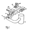
- Figure 1 is a schematic view of the spectrophotoscopic apparatus which includes the invention according to the application, in communication with a process stream;
- Figure 2 is a perspective view of the spectrometer and sample cell shown in Figure 1;
- Figure 3 is a perspective view of a heat insulative and reflective barrier which protects the spectrometer from heat given off by the sample cell;
- Figure 4 is a schematic of a Fourier Transform infrared spectrometer with a Michelson interferometer used in connection with the sample cell according to this invention;
- Figure 5 is an exploded perspective view of a sample cell according to an embodiment of the invention;
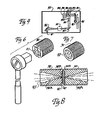
- Figure 6 is a perspective view of one embodiment of a window retainer according to the present invention;
- Figure 7 is a perspective view from the end opposite that shown in Figure 6 of a window retainer in accordance with the invention;
- Figure 8 is a cross-section of the retainers shown in Figures 6 and 7;
- Figure 9 is a vertical cross-section, with parts omitted for clarity, showing the valving arrangement and observation chamber of the sample cell; and
- Figure 10 is a horizontal cross-section of the sample cell shown in Figure 9, with parts omitted for clarity, showing the valving arrangement and the observation chamber of the invention.
- Referring now specifically to the drawings, a spectrophotometric apparatus according to the present invention is broadly illustrated and designated by reference numeral 10. Apparatus 10 samples a material moving in a
process stream 11. For the purposes of description of the invention, the material in the process stream is considered to be polymer melt which is flowing downstream of a source such as areaction vessel 12 where the polymer is created. Of course, in other environments the upstream source may be a heated vessel where polymer in chip, pellet or flake form manufactured elsewhere is reheated to its melted state for further processing. Polymer melt is diverted from theprocess stream 11 through afeeder line 13 which is contained within aninsulated jacket 13A to maintain the polymer- its process stream temperature. Flow to
feeder line 13 may be controlled by a feed pump 13B and agate valve 15. Polymer melt flows fromfeeder line 13 into asample cell 14 according to the present invention. The sample is analyzed by infrared radiation by means of aspectrometer 50. The analysis process is controlled by a computer 60 which also displays the infrared spectra generated by the analysis of the polymer melt. The analysis shown on the display terminal of the computer 60 can be obtained in hard copy form from aplotter 70. The temperature of the polymer melt withinsample cell 14 is controlled by a temperature regulator 80, as will be described in further detail below. - Referring now to Figure 2, the
spectrometer 50 is contained within ahousing 51 which includes abay 52 within whichsample cell 14 is positioned. -
Spectrometer 50 is illustrated in further detail in Figure 4. An infrared radiation source 90 is reflected at right angles off a mirror 91 and through a beam splitter 92. Fifty percent of the infrared light is reflected to a fixedmirror 93 and 50 percent of the light is transmitted to a moving mirror 94. The fixed mirror 93 returns the infrared radiation by reflection back to the beam splitter along a fixed optical path. The moving mirror 94 reflects radiation back at pathlengths that are variable and thus may differ from the fixed mirror. The reflected beams then recombine at the beam splitter 92 and a portion of this recombined beam is directed to a focusinglens 95.Lens 95 directs the converging infrared beam to a focus point withinsample cell 14 where the infrared beam again diverges. The beam is reflected again by a focusing lens 96 to an infrared detector 97. A laser 98 is used to measure the change in optical path difference withinspectrometer 50. The laser 98 emits a beam with a very precise interference pattern which yields an interferogram which is a cosine wave. This cosine wave triggers the digitization of the detector signal.Spectrometer 50 also includes a laser detector 99 and awhite light detector 100. -
Spectrometer 50 is very susceptible to heat. Since, as described below, the polymer melt must be maintained at its process stream temperature, an L-shapedinsulated barrier 54 is positioned withinbay 52 and prevents heat fromsample cell 14 from damaginginferometer 50. As is best shown in Figure 3,barrier 54 comprises a right angle structure ofinsulative material 54, such as a product known as Microfelt onto which is bonded a highly polished, reflective aluminum orchrome steel sheet 55.Sample cell 14 is mounted inbay 52 throughaccess port 56. - deferring now tc Figure 5,
sample cell 14 is described in detail. The core ofsample cell 14 is a steel block 18 into which is formed aconduit 19.Conduit 19 is substantially U-shaped and begins at a threadedinlet 20 which connects withfeeder line 13 and ends at anoutlet 21 directly beneathinlet 20 which discharges polymer melt into adischarge line 16. - Two longitudinally extending
bores 22 and 23 are formed in block 18 and receive elongate resistance-type heaters 24 and 25.Heaters 24 and 25parallel conduit 19 in relatively close relation and are intended to maintain the polymer within block 18 at its process stream temperature. Two additional bores 26 and 28 containelongate resistance heaters 29 and 30, which maintain the polymer melt at its process stream temperature in the area of the observation chamber, as described below. A thermocouple 31 monitors the temperature in the vicinity ofheaters 29 and 30. A like thermocouple 32 monitors the temperature of the block 18 in the area ofheaters 24 and 25.Heaters 24, 25, 26 and 28, and thermocouples 31 and 32 are controlled and monitored by regulator 80. - A threaded temperature sample
valve access port 33 is formed in block 18 and communicates withconduit 19. Aplug valve 34 having mating threads thereon is positioned in samplevalve access port 33 and is movable between positions wherein polymer melt is permitted to flow into the observation zone and a closed position at which flow to the observation zone is not permitted. A bypassvalve access port 35 is formed in block 18 and also communicates withconduit 19. Abypass plug valve 36 with mating threads thereon is positioned inbypass access port 35 and is movable between open and closed positions. The function of these valves is further explained with reference to Figures 9 and 10, below. A threaded retainer bore 37 is formed in and extends through block 18 from one side to the other. A threadedretainer 38 is positioned inbore 37 from one side and a like threadedretainer 39 is positioned inbore 37 from the other side. - Referring now to Figures 6, 7 and 8, the structure of
retainers retainers apertures recess 38 and anannular recess 39B is formed in one end ofretainer 39. Disk-shapedcrystals 40 of an infrared transmissible substance such as zinc selinide (ZnSe) are fixedly secured intorecesses 38B and 39B by a high temperature adhesive such as epoxy cement. Thecrystals 40 form "windows" through which infrared radiation is directed.which for example are .72 in. (18mm) in diameter and .16 in. (4mm) thick are supported on virtually their entire surface area by
retainers crystals 40 to withstand very high temperature and pressure. - As shown in Figure 6,
retainer 38 includes in its end opposite crystal 40 asquare cutout 41 adapted to receive the socket of a socket wrench. This is but one of many means by which either one or the other or both ofretainers - As is shown in Figures 9 and 10, bore 37 intersects
conduit 19 downstream of samplevalve access port 33.Retainers bore 37 in closely spaced-apart relation. The space betweencrystals 40 inretainers observation chamber 42. As polymer melt flows fromconduit 19 into and throughobservation chamber 42, it is exposed to the transmission of infrared radiation through it from side to the other. - With
sample valve 34 in the open position, the polymer melt flows betweencrystals 40 ofretainers conduit 19 and exits throughdischarge outlet 21 intodischarge line 16.Discharge line 16 can be valved with avalve 17 so that the polymer melt may be discarded or reintroduced back into theprocess stream 11, as desired. - If sampling is not carried on continuously,
sample valve 34 is closed andbypass valve 36 is opened at predetermined intervals. In this configuration, the polymer melt is blocked from enteringobservation chamber 42 and instead passes through bypassvalve access port 35 intoconduit 19 upstream ofobservation chamber 42 and out throughdischarge outlet 21, as described above. - There is a third possibility for routing polymer melt through block 18. This involves having
sample valve 34 andbypass valve 36 both open to a predetermined extent. This would most usually be done when continuous sampling is desired. In this procedure,sample valve 34 is opened sufficiently so that, for example, approximately 10 percent of the polymer melt inconduit 19 flowspast sample valve 34 and intoobservation chamber 42.Bypass valve 36 is opened to a considerably greater extent so that the remaining 90 percent of the polymer melt bypassesobservation chamber 42 and exits throughdischarge outlet 21. By regulatingsample valve 34
valve 35 restive to each other, the percentage of the polymer melt inconduit 19 which is sampled and analyzed inobservation chamber 42 can be varied to obtain a more rapid sample. - Referring again to Figure 5, the remaining components of
sample cell 14 will be briefly described. Block 18 is contained within an insulated cover 43. Suitable apertures are formed in cover 43 to permit access to block 18. Block 18 is supported within cover 43 by the insulation and also by a pair of stand-offs 44 and 45 which attach to the cover 43 by screws. Block 18 and cover 43 are secured withinbay 52 ofspectrometer 50 by means of amale mounting plate 46 which is secured through cover 43 to block 18 by screws 47 and stand-offs 48, one of each of which is shown in Figure 5.Holder 46 mates with afemale holder 49 mounted inbay 52 ofspectrometer 50.Holders apertures adjustable tubes retainers sample cell 14. Ordinarily,tubes - Referring again to Figure 8,
retainers observation chamber 42. By adjusting the distance betweenretainers retainers retainers observation chamber 42 is determined empirically by moving the twocrystals 40 into contact with each other and then backing one or both of theretainers bore 37 and observing the effect on the absorption rate of the material achieved by increasing the pathlength accordingly. Insofar as in known, the maximum effective pathlength for sampling polymer melt is no more than about 30,000ths of an inch (.76 mm). - The use of the
sample cell 14 above permits accurate spectrophotometric analysis of a material within a process stream. In addition to the use of infrared radiation, radiation in the visible, ultraviolet and other spectra can be used. One major advantage of thesample cell 14 is that the sample is taken and analyzed in a noninvasive manner, as distinguished from the invasive probe known in the prior art. - Coistent with the significant temperatures and pressures to which

sample 14 may be exposed, its primary components are constructed of high-grade stainless steel. All of the conduits are polished, as are the machine threads. In addition, the threads can be wrapped with Teflon tape. No brass, copper or other material which might react with the material being analyzed is used. - Finally, a pressure transducer, not shown in the drawings, may be provided to monitor pressure within
conduit 19. - A sample cell for the chemical analysis of a material in a moving process stream by spectrophotometric means is described above. Various details of the invention may be changed without departing from its scope. Furthermore, the foregoing description of a preferred embodiment of a sample cell according to the present invention is provided for the purpose of illustration only and not for the purpose of limitation - the invention being defined by the claims.
- The following part of the description covers
preferred embodiments 11 to 32 with reference to the wording of the claims presented. - 11. In a spectrophotometric apparatus according to Claim 9, wherein said spectrophotometric apparatus comprises an infrared radiation transmitter and detector.
- 12. In a spectrophotometric apparatus according to
Claims 9, 10 or 11, wherein the configuration of said observation chamber is variable whereby the pathlength of the radiation through the sample of material can be varied to regulate absorption of radiation by the amount of sample of material. - 13. In a spectrophotometric apparatus according to
Claim 12, and including valve means for selectably- (a) directing material into and through said observation chamber, or
- (b) directing material into an outlet from said sample cell without first passing through said observation chamber.
- .4. In a spectrophotometric apparatus according to
claim 12, and including valve means cooperating with said sample cell for selectably- (a) directing material into and through said observation chamber,
- (b) directing material out of said sample cell without first passing through said observation chamber, or
- (c) simultaneously directing a first portion of the material through said observation chamber and a second portion out of said sample cell without first passing through said observation chamber.
- 15. In a spectrophotometric apparatus according to Claim 9, wherein said material comprises a polymer melt and said sample cell includes heating means for maintaining said polymer melt at process stream temperature and pressure during analysis.
- 16. A sample cell for chemical analysis of polymer melt in a moving process stream by spectrophotometric means, said sample cell comprising:
- (a) a housing defining a conduit therein communicating with the process stream by means of a housing inlet;
- (b) heating means for maintaining the polymer melt at process stream temperature while in said housing;
- (c) an enclosed observation chamber formed in said housing in communication with said conduit, said observation chamber defined by
- (1) a first radiation transmissible window;
- (2) a second radiation transmissible window positioned in spaced-apart relation to said first radiation transmissible window and defining therebetween a pathlength through which moves polymer melt of the process stream;
- (3) said first window adapted to receive and transmit radiation of a predetermined spectrum therethrough into said observation chamber and past a focal point in the polymer melt flow within the observation chamber to generate spectral data representing a chemical analysis of the polymer melt, and
- (4) said second window adapted to receive the radiation containing the spectral data from the observation chamber and transmit it downstream for processing; and
- (d) said conduit in said housing including an outlet for discharging polymer melt from said housing.
- 17. A sample cell according to
Claim 16, and including valve means cooperating with said conduit for selectably- (a) directing polymer melt into and through said observation chamber, or
- (b) directing polymer melt into the outlet without first passing through said observation chamber.
- 18. A sample cell according to
Claim 16, and including valve means cooperating with said conduit for selectably- (a) directing polymer melt into and through said observation chamber, or
- (b) directing polymer melt into the outlet without first passing through said observation chamber, or
- (c) simultaneously directing a first predetermined portion of the polymer melt through said observation chamber and simultaneously a second predetermined portion of the polymer melt into the outlet without first passing through said observation chamber.
- 19. A sample cell according to
Claim 16, wherein the radiation transmitted by the spectrophotometric means comprises infrared radiation, and wherein said first and second radiation transmissible windows comprise an infrared transmissible material. - 20. A sample cell according to
Claim 16, wherein at least one of said first and second windows is movable relative to the other of said first and second windows to vary the space between said first and second windows and therefore the pathlength in the observation chamber through which the polymer melt moves. - 21. A sample cell according to
Claim 16, wherein both said first window and said second window are movable relative to each other to vary the space therebetween and therefore the pathlength in the observation chamber through which the polymer melt moves. - 22. A sample cell according to
Claim - 23. A sample cell according to
Claim 16, wherein the pathlength in the observation chamber is variable between a usable range of infinitesimal and 30,000ths of an inch (.76 millimeters). - 24. A sample cell according to
Claim - 25. A method for chemically analyzing a material in a moving process stream by spectrophotometric means, comprising the steps of:
- (a) diverting a sample of material from the process stream into an observation zone;
- (b) carrying out spectrophotograhic analysis by transmission of radiation through the material from one side of the material to the other; and
- (c) discharging the material from the observation zone.
- 26. A method according to Claim 25, and including the further step of adjusting the pathlength of the radiation through the material to vary absorption of radiation by the material.
- 27. A method according to Claim 25, and including the step of discharging the material to waste after analysis in the observation zone.
- 28. A method according to Claim 25, and including the step of reintroducing the material into the moving process stream after analysis in said observation zone.
- 29. A method according to Claim 25, and including the steps of:
- (d) dividing the moving process stream into a first portion which is diverted from the process stream into said observation zone for spectrophoto- graphic analysis by transmitting radiation through the material; and
- (e) diverting a second portion around observation zone without analysis for discharge to waste or reintroduction into the moving process stream.
- 30. A method according to Claim 25, wherein said material comprises polymer melt and said method includes the step of:
- (d) heating the polymer melt during diversion to the observation zone and during movement back into the moving process stream in order to maintain said polymer melt at process stream temperature and pressure during analysis.
- 31. A method according to Claim 25, 26, 27, 28 or 29, wherein said radiation comprises infrared radiation.
- 32. A method according to Claim 25, 26, 27, 28, or 29, wherein the step of spectrophotographically analyzing said material comprises the steps of directing said radiation through a first radiation transmissible window and into said observation zone; receiving the radiation after passage through the first radiation transmissible window and after passage through said material and transmitting said radiation containing spectral data relating to the material downstream for processing.
Claims (10)
Applications Claiming Priority (2)
| Application Number | Priority Date | Filing Date | Title |
|---|---|---|---|
| US06/831,296 US4717827A (en) | 1986-02-20 | 1986-02-20 | Apparatus for on-line spectrophotometric chemical analysis of material in moving process stream |
| US831296 | 1986-02-20 |
Publications (2)
| Publication Number | Publication Date |
|---|---|
| EP0246399A2 true EP0246399A2 (en) | 1987-11-25 |
| EP0246399A3 EP0246399A3 (en) | 1988-03-30 |
Family
ID=25258752
Family Applications (1)
| Application Number | Title | Priority Date | Filing Date |
|---|---|---|---|
| EP87102438A Withdrawn EP0246399A3 (en) | 1986-02-20 | 1987-02-20 | Method and apparatus for on-line spectrophotometric chemical analysis of material in moving process stream |
Country Status (5)
| Country | Link |
|---|---|
| US (1) | US4717827A (en) |
| EP (1) | EP0246399A3 (en) |
| JP (1) | JPS62259043A (en) |
| KR (1) | KR870008180A (en) |
| IN (1) | IN166543B (en) |
Cited By (2)
| Publication number | Priority date | Publication date | Assignee | Title |
|---|---|---|---|---|
| EP0322611A3 (en) * | 1987-12-31 | 1990-07-25 | AUTOMATIK Apparate-Maschinenbau GmbH | Apparatus and method for spectrophotometric analysis of a material in a moving process stream |
| WO1997014951A1 (en) * | 1995-10-18 | 1997-04-24 | Shell Internationale Research Maatschappij B.V. | Transmission cell for measuring near infrared spectra of a hydrocarbonaceous material |
Families Citing this family (18)
| Publication number | Priority date | Publication date | Assignee | Title |
|---|---|---|---|---|
| US4861999A (en) * | 1987-08-20 | 1989-08-29 | Gough Terrance E | Supersonic nozzle for use in an infrared spectrometer |
| US4910403A (en) * | 1988-11-02 | 1990-03-20 | Flow Vision, Inc. | Sampling flow cell with diamond window |
| DE3838371A1 (en) * | 1988-11-11 | 1990-05-17 | Hench Automatik App Masch | MEASURING CELL FOR SPECTRAL ANALYSIS OF FLOWING MEDIA, ESPECIALLY PLASTIC MELTS |
| JPH03110358U (en) * | 1990-02-28 | 1991-11-12 | ||
| DE4036201A1 (en) * | 1990-11-14 | 1992-05-21 | Bayer Ag | SPECTROSCOPIC ANALYSIS METHOD FOR PLASTIC MIXTURES |
| US5369483A (en) * | 1993-05-07 | 1994-11-29 | Basf Corporation | Analysis of polymer melt stream |
| US5519220A (en) * | 1994-06-28 | 1996-05-21 | Janos Technology Inc. | FTIR chemical reaction monitor |
| US5638171A (en) * | 1995-03-03 | 1997-06-10 | Honig; Jordan S. | Spectrophotometer with self-contained module |
| JP3301049B2 (en) * | 1995-05-29 | 2002-07-15 | 株式会社堀場製作所 | Gas analyzer using ultraviolet fluorescence analysis |
| BE1009667A3 (en) * | 1995-09-25 | 1997-06-03 | Solvay | Method and device for quality control vinyl latex polymers halgogenated. |
| US5808301A (en) * | 1996-12-18 | 1998-09-15 | Northern Telecom Limited | Testing of properties in flowable materials |
| US6635224B1 (en) * | 1998-10-30 | 2003-10-21 | General Electric Company | Online monitor for polymer processes |
| US20020060020A1 (en) * | 2000-07-12 | 2002-05-23 | Hercules Incorporated | On-line deposition monitor |
| WO2004090515A1 (en) * | 2003-04-01 | 2004-10-21 | Nihon University | Method of measuring protein solubility, process for producing crystal and apparatus therefor |
| US7582869B2 (en) * | 2006-07-20 | 2009-09-01 | Sas Photonics, Llc | System and method for optical analysis |
| JP4712745B2 (en) * | 2007-03-06 | 2011-06-29 | 倉敷紡績株式会社 | Flow cell for transmitted light measurement |
| US20090060783A1 (en) * | 2007-09-04 | 2009-03-05 | Kenneth Charles Barrett | Polymer concentration monitoring system and use thereof |
| DK2923197T3 (en) * | 2012-11-20 | 2020-08-24 | Grainsense Oy | AN OPTICAL SAMPLING APPARATUS AND METHOD OF USING THE SAMPLING APPARATUS |
Family Cites Families (12)
| Publication number | Priority date | Publication date | Assignee | Title |
|---|---|---|---|---|
| GB667896A (en) * | 1950-07-28 | 1952-03-12 | Anglo Iranian Oil Co Ltd | Improvements relating to the measurement of the infra-red absorption of liquids |
| US2690695A (en) * | 1952-01-03 | 1954-10-05 | Perkin Elmer Corp | Variable space absorption cell |
| US2885863A (en) * | 1955-06-20 | 1959-05-12 | Phillips Petroleum Co | Control system for separation processes |
| US3177706A (en) * | 1963-01-24 | 1965-04-13 | Hughes Aircraft Co | Fluid inspection device |
| FR1538351A (en) * | 1967-04-18 | 1968-09-06 | Roussel Uclaf | Advanced sample cell device for optical measurements |
| US3614243A (en) * | 1969-08-01 | 1971-10-19 | Reno A Del Ben | Variable path-length gas cell |
| US3646313A (en) * | 1970-04-08 | 1972-02-29 | Gilford Instr Labor Inc | Temperature controlled flow cell |
| GB1305214A (en) * | 1970-10-28 | 1973-01-31 | ||
| US3886364A (en) * | 1973-06-19 | 1975-05-27 | Union Carbide Corp | High pressure infrared cell |
| JPS57118348A (en) * | 1981-01-13 | 1982-07-23 | Sony Corp | Electric-discharge displayer |
| JPS599545A (en) * | 1982-07-09 | 1984-01-18 | Hitachi Ltd | Flow cell of photometer |
| US4529306A (en) * | 1983-06-13 | 1985-07-16 | Flow Vision, Inc. | Apparatus and method for polymer melt stream analysis |
-
1986
- 1986-02-20 US US06/831,296 patent/US4717827A/en not_active Expired - Fee Related
-
1987
- 1987-02-02 KR KR870000820A patent/KR870008180A/en not_active Ceased
- 1987-02-19 JP JP62037685A patent/JPS62259043A/en active Pending
- 1987-02-20 EP EP87102438A patent/EP0246399A3/en not_active Withdrawn
- 1987-04-21 IN IN312/CAL/87A patent/IN166543B/en unknown
Cited By (2)
| Publication number | Priority date | Publication date | Assignee | Title |
|---|---|---|---|---|
| EP0322611A3 (en) * | 1987-12-31 | 1990-07-25 | AUTOMATIK Apparate-Maschinenbau GmbH | Apparatus and method for spectrophotometric analysis of a material in a moving process stream |
| WO1997014951A1 (en) * | 1995-10-18 | 1997-04-24 | Shell Internationale Research Maatschappij B.V. | Transmission cell for measuring near infrared spectra of a hydrocarbonaceous material |
Also Published As
| Publication number | Publication date |
|---|---|
| EP0246399A3 (en) | 1988-03-30 |
| JPS62259043A (en) | 1987-11-11 |
| US4717827A (en) | 1988-01-05 |
| IN166543B (en) | 1990-06-02 |
| KR870008180A (en) | 1987-09-24 |
Similar Documents
| Publication | Publication Date | Title |
|---|---|---|
| US4717827A (en) | Apparatus for on-line spectrophotometric chemical analysis of material in moving process stream | |
| US4888484A (en) | Apparatus and method for spectrophotometric analysis of a material in a moving process stream | |
| Siesler | Near‐infrared spectroscopy of polymers | |
| US5886347A (en) | Analytical method for multi-component aqueous solutions and apparatus for the same | |
| Compton et al. | In situ FT-IR analysis of a composite curing reaction using a mid-infrared transmitting optical fiber | |
| US5879629A (en) | Process flow injection analyzer and method | |
| US8400637B2 (en) | Signal processing for optical computing system | |
| EP0717845B1 (en) | Sampling and analysis system and method | |
| EP2078187A2 (en) | Multi-analyte optical computing system | |
| Watari et al. | On-line monitoring of the density of linear low-density polyethylene in a real plant by near-infrared spectroscopy and chemometrics | |
| US6166804A (en) | Method and apparatus for obtaining fluorescence data | |
| US4910403A (en) | Sampling flow cell with diamond window | |
| US5455177A (en) | Method for analysis of a medical sample | |
| Mirabella Jr | Simultaneous differential scanning calorimetry (DSC) and infrared spectroscopy using an infrared microsampling accessory (IRMA) and FT-IR | |
| US20020067481A1 (en) | Transmission spectroscopy apparatus for vessels | |
| Coates | The industrial applications of infrared internal reflectance spectroscopy | |
| Watari et al. | Prediction of ethylene content in melt-state random and block polypropylene by near-infrared spectroscopy and chemometrics: comparison of a new calibration transfer method with a slope/bias correction method | |
| Watari | Applications of near-infrared spectroscopy to process analysis using fourier transform spectrometer | |
| Reshadat et al. | In-line near-infrared monitoring of polymer processing. Part I: Process/monitor interface development | |
| Chung et al. | Near-infrared spectroscopy for on-line monitoring of lube base oil processes | |
| CN87103339A (en) | Method and apparatus for on-line spectrophotometric chemical analysis of materials in a flowing process stream | |
| Kaiser et al. | Critical and statistically based evaluation, testing, comparison and optimization of capillary chromatography systems, the “ABT-concept” in capillary GC | |
| GB2104681A (en) | Apparatus for the continuous investigation of chemical reactions by infrared (IR) absorption | |
| JPH0640070B2 (en) | Fourier transform infrared spectrophotometer measuring device with differential scanning calorimeter | |
| Arendale et al. | Spectroscopy and multivariate analyses applications related to solid rocket nozzle bondline |
Legal Events
| Date | Code | Title | Description |
|---|---|---|---|
| PUAI | Public reference made under article 153(3) epc to a published international application that has entered the european phase |
Free format text: ORIGINAL CODE: 0009012 |
|
| AK | Designated contracting states |
Kind code of ref document: A2 Designated state(s): AT BE CH DE ES FR GB GR IT LI LU NL SE |
|
| RBV | Designated contracting states (corrected) |
Designated state(s): BE CH DE FR GB IT LI NL |
|
| PUAL | Search report despatched |
Free format text: ORIGINAL CODE: 0009013 |
|
| AK | Designated contracting states |
Kind code of ref document: A3 Designated state(s): BE CH DE FR GB IT LI NL |
|
| 17P | Request for examination filed |
Effective date: 19880816 |
|
| 17Q | First examination report despatched |
Effective date: 19891222 |
|
| STAA | Information on the status of an ep patent application or granted ep patent |
Free format text: STATUS: THE APPLICATION HAS BEEN WITHDRAWN |
|
| 18W | Application withdrawn |
Withdrawal date: 19910111 |
|
| RIN1 | Information on inventor provided before grant (corrected) |
Inventor name: HARVEY, ROBERT J. |