EP0246332A1 - Guide-fil pour decoupage par fil a electro-erosion - Google Patents
Guide-fil pour decoupage par fil a electro-erosion Download PDFInfo
- Publication number
- EP0246332A1 EP0246332A1 EP86906926A EP86906926A EP0246332A1 EP 0246332 A1 EP0246332 A1 EP 0246332A1 EP 86906926 A EP86906926 A EP 86906926A EP 86906926 A EP86906926 A EP 86906926A EP 0246332 A1 EP0246332 A1 EP 0246332A1
- Authority
- EP
- European Patent Office
- Prior art keywords
- guide
- wire
- wire electrode
- arc
- taper
- Prior art date
- Legal status (The legal status is an assumption and is not a legal conclusion. Google has not performed a legal analysis and makes no representation as to the accuracy of the status listed.)
- Granted
Links
Images


Classifications
-
- B—PERFORMING OPERATIONS; TRANSPORTING
- B23—MACHINE TOOLS; METAL-WORKING NOT OTHERWISE PROVIDED FOR
- B23H—WORKING OF METAL BY THE ACTION OF A HIGH CONCENTRATION OF ELECTRIC CURRENT ON A WORKPIECE USING AN ELECTRODE WHICH TAKES THE PLACE OF A TOOL; SUCH WORKING COMBINED WITH OTHER FORMS OF WORKING OF METAL
- B23H7/00—Processes or apparatus applicable to both electrical discharge machining and electrochemical machining
- B23H7/02—Wire-cutting
- B23H7/08—Wire electrodes
- B23H7/10—Supporting, winding or electrical connection of wire-electrode
Definitions
- This invention relates to an improvement applicable to a wire guide for wire electrode type electrical discharge machining. More specifically, this invention relates to an improvement applicable to a wire guide for wire electrode type electrical discharge machining, for the purpose to enable the wire guide to be employed both for taper machining and for non-taper machining with high machining accuracy, regardless of the magnitude of the taper angle thereof and to enable the wire guide to be readily attached by (or threaded with) a wire electrode and additionally to enable the wire guide to be employed for a wire electrode type electrical discharge machining equipment equipped with an automatic wire electrode connecting (or threading) system.
- Wire guides for wire electrode type electrical discharge machining available in the prior art are classified into some models described below.
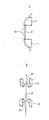
- V-groove guide has a V-shaped groove along which a wire electrode 2 is guided.
- this wire guide 1 ia readily attached by (or threaded with) a wire electrode 2, or although it is easy to attach a wire electrode 2 to this guide 1, this V-groove guide is not suitable for taper machining.
- Die guide
- a die guide has an aperture 31 through which a wire electrode 2 passes.
- the die guide 3 is suitable for taper machining.
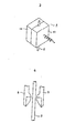
- three-point-supporting guide is a combination of a V-groove guide member 41 and a supporting guide member 42.
- This three-point-supporting guide 4 has a feature to support a wire guide 2 accurately at a requird location during a period in which a machining is conducted and to be readily attached by (or threaded with) a wire electrode 2 by moving the supporting guide member 42 apart from the V-groove guide member 41, when a wire electrode 2 is attached thereby (or threaded therewith).
- an arc-shaped guide is a type of die guide of which the radius of curvature of the surface of the aperture 51 is extremely large.
- This arc-shaped guide 5 has a feature not to cause a wire electrode 2 to be sharply bent, even if the taper angle is large, resultantly causing no large magnitude of friction to be applied to the wire electrode 2.
- the object of this invention is to provide a wire guide employable for wire electrode type electrical discharge machining having the following features.
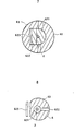
- a wire guide employale for wire electrode type electrical discharge machining in accordance with this invention shown by 6 in F ig. 5, is provided an arc-shaped guide 61 which is arranged at a location concentric with a wire electrode 2, a three-point-supporting guide 62 which is arranged closely to the arc-shaped guide 61 along the wire electrode 2 for allowing the wire electrode 2 to pass therethrough, an external tube member 63 for holding the arc-shaped guide 61 and the three-point-supporting guide 62 therein, having a center hole 631 for allowing the wire electrode 2 to pass therethrough and having a cooling liquid supply hole 632 for supplying a cooling liquid for cooling the wire electrode 2.
- the wire guide 6 for wire electrode type electrical discharge machining in accordance with this invention functions as an arc-shaped guide 61, when the taper angle is large, and functions as a three-point-supporting guide 62, when the taper angle is small.
- either of these two guides is automatically selected depending on the taper angle, and a high level of machining accuracy is realized, regardless of the magnitude of the taper angle.
- this wire guide 6 When this wire guide 6 is employed for non-taper machining, this wire guide 6 functions as a three-point-supporting guide 62, realizing a high level of machining accuracy. As a result, this wire guide 6 causes a high magnitude of machining accuracy both for taper machining and for non-taper machining.
- this wire guide 6 When this wire guide 6 is attached by (or threaded with) a wire electrode 2, the three-point-supporting guide 62 allows the supporting guide member 622 to remove apart from the V-groove guide member 621 to make the gap therebetween large. In addition, the diameter of the aperture of the arc-shaped guide is selected relatively large. These two parameters allow the wire guide of this invention to be readily threaded with the wire electrode 2. As a result, this wire guide 6 can be employed for a wire electrode type electrical discharge machining equipment provided an automatic wire connecting (or threading) system.
- an arc-shaped guide 61 is assembled in an external tube 63.
- the arc-shaped guide 61 has a center hole whose diameter is selected to be larger (by for example 0.1mm) than the diameter (usually 0.05-0.3mm) of a wire electrode 2, for the purpose to enable the arc-shaped guide 61 to be readily attached by (or threaded with) the wire electrode 2.
- a three-point-supporting guide 62 is assembled in the external tube 63 closely to the arc-shaped guide 61.
- the three-point-supporting guide 62 consists of a V-groove guide member 621, a supporting guide member 622 and a spring 623 (shown as a leaf spring in the drawing).
- the supporting guide member 622 is urged towards the V-groove guide member 621 by a spring tension adjustment means which is shown by a numeral 71 in Fig. 9, against the tension of the spring 623.
- the wire electrode 2 is held accurately at the center of the center hole 631 of the wire guide 6.
- the external tube 63 functions to hold the V-groove guide member 621 at an accurate position relative to the supporting guide member 622, in addition to a function to allow the wire electrode 2 to pass through the internal hole 631 and to supply a cooling liquid through a cooling liquid supply hole 632.
- the wire guide 6 when the wire guide .6 for wire electrode type electrical discharge machining is employed, the wire guide 6 is arranged in a nozzle 7 having the spring tension adjustment means which adjusts the tension of the spring 623 (A coil spring is shown in Fig. 9.), before a cooling liquid is supplied through the cooling liquid supply hole 72 and the wire electrode 2 is arranged as shown in Fig. 9.
Landscapes
- Chemical & Material Sciences (AREA)
- Chemical Kinetics & Catalysis (AREA)
- Electrochemistry (AREA)
- Engineering & Computer Science (AREA)
- Mechanical Engineering (AREA)
- Electrical Discharge Machining, Electrochemical Machining, And Combined Machining (AREA)
Abstract
Applications Claiming Priority (2)
| Application Number | Priority Date | Filing Date | Title |
|---|---|---|---|
| JP1985175827U JPS6285329U (fr) | 1985-11-14 | 1985-11-14 | |
| JP175827/85U | 1985-11-14 |
Publications (3)
| Publication Number | Publication Date |
|---|---|
| EP0246332A1 true EP0246332A1 (fr) | 1987-11-25 |
| EP0246332A4 EP0246332A4 (fr) | 1988-12-01 |
| EP0246332B1 EP0246332B1 (fr) | 1991-04-03 |
Family
ID=16002911
Family Applications (1)
| Application Number | Title | Priority Date | Filing Date |
|---|---|---|---|
| EP86906926A Expired - Lifetime EP0246332B1 (fr) | 1985-11-14 | 1986-11-12 | Guide-fil pour decoupage par fil a electro-erosion |
Country Status (6)
| Country | Link |
|---|---|
| US (1) | US4803328A (fr) |
| EP (1) | EP0246332B1 (fr) |
| JP (1) | JPS6285329U (fr) |
| KR (1) | KR940000364B1 (fr) |
| DE (1) | DE3678571D1 (fr) |
| WO (1) | WO1987002920A1 (fr) |
Cited By (6)
| Publication number | Priority date | Publication date | Assignee | Title |
|---|---|---|---|---|
| EP0463103A1 (fr) * | 1989-03-17 | 1992-01-02 | Fort Wayne Wire Die Inc | Ensemble de guidage de fil-electrode mobile pour appareil de machine de decharge electrique. |
| EP0585714A1 (fr) * | 1992-08-26 | 1994-03-09 | AG für industrielle Elektronik AGIE Losone bei Locarno | Dispositif pour le découpage par électroérosion |
| EP0826952A2 (fr) * | 1996-09-03 | 1998-03-04 | W. SCHLAFHORST AG & CO. | Mesure de la force de tension des fils dans les dispositifs de guidage des fils |
| CN103100867A (zh) * | 2012-11-06 | 2013-05-15 | 无锡市航鹄科技有限公司 | 线切割加工斜面工装 |
| CN106312211A (zh) * | 2016-09-30 | 2017-01-11 | 淮安信息职业技术学院 | 电火花快速走丝线切割机床电极丝夹紧定位装置 |
| CN113042833A (zh) * | 2021-03-30 | 2021-06-29 | 合肥工业大学 | 一种薄壁圆筒群孔加工装置及其加工方法 |
Families Citing this family (12)
| Publication number | Priority date | Publication date | Assignee | Title |
|---|---|---|---|---|
| US4937414A (en) * | 1988-09-12 | 1990-06-26 | Perreault David J | Wire guide for electrical discharge machining apparatus |
| US5003148A (en) * | 1988-10-11 | 1991-03-26 | Fort Wayne Wire Die, Inc. | Method of threading electrode through EDM guide |
| US4994643A (en) * | 1989-03-17 | 1991-02-19 | Fort Wayne Wire Die, Inc. | Electrical discharge machine apparatus tilted current pickup |
| US5095734A (en) * | 1990-12-14 | 1992-03-17 | William L. Bonnell Company, Inc. | Extrusion die and method for extruding aluminum |
| US5384444A (en) * | 1992-12-23 | 1995-01-24 | Basix Technologies Ltd. | Sleeve forming wire passageway around pickup |
| US5430268A (en) * | 1992-12-23 | 1995-07-04 | Basix Technologies Ltd. | Method and apparatus for adjusting and replacing EDM components from the guide assembly working end |
| US5380973A (en) * | 1992-12-23 | 1995-01-10 | Basix Technologies Ltd. | Current pickup indexing apparatus |
| US6007694A (en) * | 1998-04-07 | 1999-12-28 | Phillips Plastics Corporation | Electrochemical machining |
| US9375801B2 (en) * | 2008-10-23 | 2016-06-28 | Arben Cenko | Rotary welding torch |
| CN103406619A (zh) * | 2013-08-07 | 2013-11-27 | 苏州市合昌电器有限公司 | 电极丝绕丝器 |
| US9776267B1 (en) * | 2016-06-14 | 2017-10-03 | Johnson Technology, Inc. | Electrical discharge machining electrode holder |
| CN114749740B (zh) * | 2022-04-13 | 2024-04-05 | 泰州文杰数控设备有限公司 | 一种中走丝电火花线切割机床的切割方法 |
Family Cites Families (5)
| Publication number | Priority date | Publication date | Assignee | Title |
|---|---|---|---|---|
| CH594477A5 (fr) * | 1976-08-20 | 1978-01-13 | Agie Ag Ind Elektronik | |
| JPS56116119U (fr) * | 1980-01-29 | 1981-09-05 | ||
| JPS58186534A (ja) * | 1982-04-27 | 1983-10-31 | Fanuc Ltd | ワイヤカツト放電加工用ワイヤ電極ガイドシステム |
| JPS59156626A (ja) * | 1983-02-28 | 1984-09-05 | Fanuc Ltd | ワイヤカツト放電加工用ダイスガイド |
| JPS59232727A (ja) * | 1983-06-14 | 1984-12-27 | Fanuc Ltd | ワイヤカツト放電加工用ワイヤ電極ガイド装置 |
-
1985
- 1985-11-14 JP JP1985175827U patent/JPS6285329U/ja active Pending
-
1986
- 1986-11-12 DE DE8686906926T patent/DE3678571D1/de not_active Expired - Lifetime
- 1986-11-12 KR KR1019870700608A patent/KR940000364B1/ko not_active IP Right Cessation
- 1986-11-12 EP EP86906926A patent/EP0246332B1/fr not_active Expired - Lifetime
- 1986-11-12 WO PCT/JP1986/000578 patent/WO1987002920A1/fr active IP Right Grant
- 1986-11-12 US US07/085,406 patent/US4803328A/en not_active Expired - Fee Related
Non-Patent Citations (1)
| Title |
|---|
| See references of WO8702920A1 * |
Cited By (11)
| Publication number | Priority date | Publication date | Assignee | Title |
|---|---|---|---|---|
| EP0463103A1 (fr) * | 1989-03-17 | 1992-01-02 | Fort Wayne Wire Die Inc | Ensemble de guidage de fil-electrode mobile pour appareil de machine de decharge electrique. |
| EP0463103A4 (en) * | 1989-03-17 | 1992-07-08 | Fort Wayne Wire Die, Inc. | Electrical discharge machine apparatus moving wire electrode guide assembly |
| EP0585714A1 (fr) * | 1992-08-26 | 1994-03-09 | AG für industrielle Elektronik AGIE Losone bei Locarno | Dispositif pour le découpage par électroérosion |
| US5428200A (en) * | 1992-08-26 | 1995-06-27 | A.G. Fur Industrielle Elektronik Agie | Apparatus for electro-erosion cutting |
| EP0826952A2 (fr) * | 1996-09-03 | 1998-03-04 | W. SCHLAFHORST AG & CO. | Mesure de la force de tension des fils dans les dispositifs de guidage des fils |
| EP0826952A3 (fr) * | 1996-09-03 | 1999-01-13 | W. SCHLAFHORST AG & CO. | Mesure de la force de tension des fils dans les dispositifs de guidage des fils |
| CN103100867A (zh) * | 2012-11-06 | 2013-05-15 | 无锡市航鹄科技有限公司 | 线切割加工斜面工装 |
| CN106312211A (zh) * | 2016-09-30 | 2017-01-11 | 淮安信息职业技术学院 | 电火花快速走丝线切割机床电极丝夹紧定位装置 |
| CN106312211B (zh) * | 2016-09-30 | 2018-05-04 | 淮安信息职业技术学院 | 电火花快速走丝线切割机床电极丝夹紧定位装置 |
| CN113042833A (zh) * | 2021-03-30 | 2021-06-29 | 合肥工业大学 | 一种薄壁圆筒群孔加工装置及其加工方法 |
| CN113042833B (zh) * | 2021-03-30 | 2022-02-11 | 合肥工业大学 | 一种薄壁圆筒群孔加工装置及其加工方法 |
Also Published As
| Publication number | Publication date |
|---|---|
| DE3678571D1 (de) | 1991-05-08 |
| JPS6285329U (fr) | 1987-05-30 |
| EP0246332A4 (fr) | 1988-12-01 |
| WO1987002920A1 (fr) | 1987-05-21 |
| KR880700706A (ko) | 1988-04-11 |
| EP0246332B1 (fr) | 1991-04-03 |
| KR940000364B1 (ko) | 1994-01-19 |
| US4803328A (en) | 1989-02-07 |
Similar Documents
| Publication | Publication Date | Title |
|---|---|---|
| EP0246332B1 (fr) | Guide-fil pour decoupage par fil a electro-erosion | |
| US6811124B2 (en) | Device for guiding a hose | |
| DE69522586D1 (de) | Manipulator für einen testkopf einer automatischen testanlage | |
| CH642181A5 (de) | Zwischenteil fuer eine loesbare steckverbindung zum kuppeln einer lichtleitungsfaser an eine halbleiterlichtquelle. | |
| ES2118404T3 (es) | Dispositivo de osteosintesis. | |
| CA2862654C (fr) | Dispositifs d'alimentation en fil de soudage avec un guide-fil ayant des surfaces de guidage allongees espacees l'une de l'autre | |
| CA2136544A1 (fr) | Porte-outils et methode pour son utilisation | |
| FR2623430B1 (fr) | Dispositif de montage a queue conique, en particulier au cone 7/24, a application cone et face pour attachements, porte-outils et outils | |
| US4151984A (en) | Selectively positional V-block fixture | |
| US4470439A (en) | Adjustable guides | |
| JPS59118317A (ja) | 工作機械における工具のための収容部 | |
| JP2624521B2 (ja) | 放電加工機の電極ガイド装置 | |
| CN216912266U (zh) | 可调节刀具位置的夹头组件及切削装置 | |
| CN211881830U (zh) | 一种可调式渔线轮座 | |
| CN211053434U (zh) | 一种砂光机底座用连接结构 | |
| JPH0420818Y2 (fr) | ||
| US4559886A (en) | Thread guide construction | |
| JP3254385B2 (ja) | テープ心線の撚り治具 | |
| JPS6215020A (ja) | ワイヤ電極のガイド部材 | |
| SU1284713A1 (ru) | Способ креплени режущего элемента | |
| SU921692A1 (ru) | Режущий инструмент | |
| SU598719A1 (ru) | Устройство дл электроэрозионной обработки | |
| ATE17667T1 (de) | Spannvorrichtung eines schneideneinsatzes auf einem werkzeughalter. | |
| JP2002001675A (ja) | 自動ねじ締付装置 | |
| SU1516323A1 (ru) | Сборный резец |
Legal Events
| Date | Code | Title | Description |
|---|---|---|---|
| PUAI | Public reference made under article 153(3) epc to a published international application that has entered the european phase |
Free format text: ORIGINAL CODE: 0009012 |
|
| 17P | Request for examination filed |
Effective date: 19870806 |
|
| AK | Designated contracting states |
Kind code of ref document: A1 Designated state(s): CH DE FR GB LI |
|
| A4 | Supplementary search report drawn up and despatched |
Effective date: 19881201 |
|
| 17Q | First examination report despatched |
Effective date: 19900723 |
|
| GRAA | (expected) grant |
Free format text: ORIGINAL CODE: 0009210 |
|
| AK | Designated contracting states |
Kind code of ref document: B1 Designated state(s): CH DE FR GB LI |
|
| REF | Corresponds to: |
Ref document number: 3678571 Country of ref document: DE Date of ref document: 19910508 |
|
| ET | Fr: translation filed | ||
| PGFP | Annual fee paid to national office [announced via postgrant information from national office to epo] |
Ref country code: GB Payment date: 19911101 Year of fee payment: 6 |
|
| PGFP | Annual fee paid to national office [announced via postgrant information from national office to epo] |
Ref country code: FR Payment date: 19911107 Year of fee payment: 6 |
|
| PLBE | No opposition filed within time limit |
Free format text: ORIGINAL CODE: 0009261 |
|
| STAA | Information on the status of an ep patent application or granted ep patent |
Free format text: STATUS: NO OPPOSITION FILED WITHIN TIME LIMIT |
|
| 26N | No opposition filed | ||
| PG25 | Lapsed in a contracting state [announced via postgrant information from national office to epo] |
Ref country code: GB Effective date: 19921112 |
|
| GBPC | Gb: european patent ceased through non-payment of renewal fee |
Effective date: 19921112 |
|
| PG25 | Lapsed in a contracting state [announced via postgrant information from national office to epo] |
Ref country code: FR Effective date: 19930730 |
|
| REG | Reference to a national code |
Ref country code: FR Ref legal event code: ST |
|
| PGFP | Annual fee paid to national office [announced via postgrant information from national office to epo] |
Ref country code: DE Payment date: 19951113 Year of fee payment: 10 |
|
| PGFP | Annual fee paid to national office [announced via postgrant information from national office to epo] |
Ref country code: CH Payment date: 19951122 Year of fee payment: 10 |
|
| PG25 | Lapsed in a contracting state [announced via postgrant information from national office to epo] |
Ref country code: LI Effective date: 19961130 Ref country code: CH Effective date: 19961130 |
|
| REG | Reference to a national code |
Ref country code: CH Ref legal event code: PL |
|
| PG25 | Lapsed in a contracting state [announced via postgrant information from national office to epo] |
Ref country code: DE Effective date: 19970801 |