EP0246111A1 - Dispositif de guidage de l'écoulement pour des échangeurs de chaleur dans des canalisations de transfert - Google Patents
Dispositif de guidage de l'écoulement pour des échangeurs de chaleur dans des canalisations de transfert Download PDFInfo
- Publication number
- EP0246111A1 EP0246111A1 EP87304339A EP87304339A EP0246111A1 EP 0246111 A1 EP0246111 A1 EP 0246111A1 EP 87304339 A EP87304339 A EP 87304339A EP 87304339 A EP87304339 A EP 87304339A EP 0246111 A1 EP0246111 A1 EP 0246111A1
- Authority
- EP
- European Patent Office
- Prior art keywords
- heat exchange
- exchange tubes
- tubesheet
- recited
- flow
- Prior art date
- Legal status (The legal status is an assumption and is not a legal conclusion. Google has not performed a legal analysis and makes no representation as to the accuracy of the status listed.)
- Withdrawn
Links
Images

Classifications
-
- F—MECHANICAL ENGINEERING; LIGHTING; HEATING; WEAPONS; BLASTING
- F28—HEAT EXCHANGE IN GENERAL
- F28F—DETAILS OF HEAT-EXCHANGE AND HEAT-TRANSFER APPARATUS, OF GENERAL APPLICATION
- F28F19/00—Preventing the formation of deposits or corrosion, e.g. by using filters or scrapers
- F28F19/002—Preventing the formation of deposits or corrosion, e.g. by using filters or scrapers by using inserts or attachments
-
- C—CHEMISTRY; METALLURGY
- C10—PETROLEUM, GAS OR COKE INDUSTRIES; TECHNICAL GASES CONTAINING CARBON MONOXIDE; FUELS; LUBRICANTS; PEAT
- C10G—CRACKING HYDROCARBON OILS; PRODUCTION OF LIQUID HYDROCARBON MIXTURES, e.g. BY DESTRUCTIVE HYDROGENATION, OLIGOMERISATION, POLYMERISATION; RECOVERY OF HYDROCARBON OILS FROM OIL-SHALE, OIL-SAND, OR GASES; REFINING MIXTURES MAINLY CONSISTING OF HYDROCARBONS; REFORMING OF NAPHTHA; MINERAL WAXES
- C10G9/00—Thermal non-catalytic cracking, in the absence of hydrogen, of hydrocarbon oils
- C10G9/002—Cooling of cracked gases
-
- F—MECHANICAL ENGINEERING; LIGHTING; HEATING; WEAPONS; BLASTING
- F28—HEAT EXCHANGE IN GENERAL
- F28D—HEAT-EXCHANGE APPARATUS, NOT PROVIDED FOR IN ANOTHER SUBCLASS, IN WHICH THE HEAT-EXCHANGE MEDIA DO NOT COME INTO DIRECT CONTACT
- F28D21/00—Heat-exchange apparatus not covered by any of the groups F28D1/00 - F28D20/00
- F28D2021/0019—Other heat exchangers for particular applications; Heat exchange systems not otherwise provided for
- F28D2021/0075—Other heat exchangers for particular applications; Heat exchange systems not otherwise provided for for syngas or cracked gas cooling systems
-
- F—MECHANICAL ENGINEERING; LIGHTING; HEATING; WEAPONS; BLASTING
- F28—HEAT EXCHANGE IN GENERAL
- F28F—DETAILS OF HEAT-EXCHANGE AND HEAT-TRANSFER APPARATUS, OF GENERAL APPLICATION
- F28F2250/00—Arrangements for modifying the flow of the heat exchange media, e.g. flow guiding means; Particular flow patterns
- F28F2250/02—Streamline-shaped elements
Definitions
- This invention relates to novel heat exchangers and to chemical processes involving their use. More particularly, this invention relates to new and improved indirect shell-and-tube heat exchangers of the type known as transfer line heat exchangers (TLEs), and to improved processes of quenching or recovering heat from high temperature fluids, and particularly high temperature gases, which involve their use.
- TLEs transfer line heat exchangers
- These novel TLEs are modified at their inlet ends in two respects in comparison to conventional TLEs by means which, taken together, can be characterized as a flow streamlining device. These modifications minimize or prevent inlet end fouling, which commonly occurs in conventional TLEs due to coke buildup resulting from condensation or precipitation, and then decomposition at high temperature, of tars, high polymers or other high molecular weight materials during processing. Their use also reduces the overall down time required to clean the inlet ends of the heat transfer tubes should inlet end fouling eventually occur.
- Transfer line heat exchangers are in widespread use in commercial chemical processing. In general, they operate to cool hot gases by passing these gases through a bundle of tubes in heat exchange relationship with a cooling fluid, such as water, passing around the outside, or shell side, of the tubes and contained within a defined area along the tubes by means of a pair of tubesheets which are generally perpendicular to the tubes contained within them. In certain processes, the heat removed from the process gas is sufficient to vaporize the fluid on the shell side. In such cases if water is used as the cooling fluid the heat exchanger also becomes a steam generator.
- a cooling fluid such as water
- TLEs are commonly used to cool very hot process gases. For example, they are used in processes for producing ammonia such as that disclosed in U.S. Patent No. 3,442, 613, issued May 6, 1969 to Grotz, to cool the approximately 850°F ammonia-containing gas exiting a syngas converter. They are also used in olefin plants and in other hydrocarbon cracking operations to recover usable heat from reactor gases, e.g., gases exiting pyrolysis furnace coils at temperatures above 1500°F. To avoid secondary reactions leading to less valuable or useless products, the residence time spent by the exiting gases between The furnace coil outlet and the TLE inlet should be minimized.
- Another object of this invention is to provide improved processes of quenching or recovering heat from high temperature fluids, and particularly high temperature gases, which involve the use of my novel transfer line heat exchangers.
- a further object of this invention is to provide novel transfer line heat exchangers whose inlet ends are modified by means of a novel flow streamlining device.
- a still further object of this invention is to provide novel transfer line heat exchangers which minimize or prevent inlet end fouling due to coke buildup.
- the novel flow streamlining device of this invention includes: -flared end means, preferably in the form of hollow truncated cones, with the smaller ends aligned with and mated to the inlet ends of the heat exchange tubes in a conventional TLE, the ends of these heat exchange tubes being contained within tubesheets which are generally perpendicular to the tubes, the flared end means extending away from the inlet end tubesheet, and -peaked gas guide means, preferably in the form of closed, concave gables having rounded, smooth tops, which rise between the rims or edges of adjacent larger ends of the flared end means and enclose the spaces between these rims or edges.
- the peaked gas guide means in combination with the flared end means, almost completely eliminate the tube sheet impact area perpendicular to the gas flow on which hot gases exiting a reactor impinge in a conventional TLE, thus lessening the opportunity for condensible or precipitatible materials in the gases entering the novel TLEs of this invention to deposit at the TLE inlet end and ultimately form coke deposits.
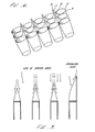
- the topology of this novel flow streamlining device is somewhat similar to that of the bottom half of an egg carton, as will be evident from accompanying FIG. 4.
- TLE inlet end fouling by coke deposit formation is chiefly due to at least one and possibly three distinct mechanisms, each of which can contribute to slow cooling at and in the vicinity of the TLE inlet end, a condition believed to be conducive to coke deposition.
- solid coke particles entrained in the entering gases can impact on TLE surfaces, particularly surfaces perpendicular to the direction of the gas flow, and progressively build up deposits on these surfaces. Ultimately, such deposits can block the inlet ends of the TLE tubes by "scaffolding" or cantilevering across the tube openings.
- nonideal gas flow distribution in the TLE at its inlet and beyond, and on the hot tubesheet can cause turbulent eddies and backmixing of the gases present, cooling them to also result in increased fouling.
- coke and pyrolysis tars, and other condensible or precipitatible materials can condense or deposit on any surface of the TLE or adjacent equipment which has been allowed to cool to below the dew point of the condensing or depositing material.
- the ratio of total tube inlet area to flat surface area on the surrounding tubesheet can be quite small.
- a typical TLE 1 may have less than 20% of the total surface area of its tubesheet 3 perforated with heat exchange tube inlets 5; see, for example, the Fuki et al, Hengstebeck and Koontz patents.
- Whatever portion of the flat surface area on the tubesheet 1 not perforated by heat exchange tube inlets 5 becomes an impact surface (the shaded area within the dotted boundary of FIG. 1, for example), one which is normally comparatively cool by virtue of contact with heat exchange fluid on its underside and thus one which can give rise to coke deposits by any or all of the above-mentioned mechanisms.
- transfer line exchanger 7 with heat exchange tube inlet ends (not shown) aligned with and mated to the smaller ends 11 of flared end means 9 in the form of hollow truncated cones, has a greatly reduced impact area on its tubesheet 13 (the shaded area within the tubesheet portion 13 of FIG. 2) in comparison to that of the TLE of FIG. 1.
- the hollow truncated cones 9 are configured in such a manner that the rims or edges of their larger ends 15 closesly abut one another, and preferably come within from zero to about 3/8 inches of one another.
- Typical dimensions for such hollow truncated cones 9 are as follows: a height as measured along the central axis of the cone of from about 5/8 to about 8 inches, and preferably from about 11 ⁇ 4 to about 21 ⁇ 2 inches, a diameter at the rim or edge of the smaller end 11 of from about 1 ⁇ 2 to about 21 ⁇ 2 inches, and preferably from about 1 to about 11 ⁇ 2 inches, and a diameter at the rim or edge of the larger end 15 of from about 3/4 to about 4 inches, and preferably from about 11 ⁇ 4 to about 21 ⁇ 2 inches, thus giving a typical pitch or slope from the smaller end 11 of the hollow truncated cone 9 to the larger end 15 of from about 5 to about 35 degrees, and preferably from about 10 to about 25 degrees.
- the peaked gas guide means 17 in the form of closed, concave gables having rounded, smooth tops 19 and concave sides 21 which gently slope downwardly from the rounded tops 19 to the rims or edges of the larger ends 15 of the hollow truncated cones 9, as shown in FIG. 3 and FIG. 4, rise between the rims or edges of the larger ends 15 of the hollow truncated cones 9 to enclose and cover the remaining flat surface area on the tubesheet 13 (again, for example, the shaded area within the tubesheet portion 13 of FIG. 2).
- the gases exiting a reactor (not shown), instead of impinging on flat tubesheet surfaces, stream down the concave sides 21 of the closed, concave gables 17, enter the enlarged inlets provided by the hollow truncated cones 9, and then pass beyond the tubesheet 13 through the TLE's heat exchange tubes 23.
- the impact area perpendicular to the gas flow at the inlet end 25 of a thus-modified TLE is almost completely eliminated, turbulent eddies and backmixing are minimized, and gases carrying entrained coke particles, tarry substances or other tar and coke formers are guided past the closed concave gables 17 through the hollow truncated cones 9 with minimal recirculation.
- a minimum amount of heat is lost by the gases in the inlet area. This helps alleviate problems caused by condensation, which in turn helps reduce coke deposits.
- the number of sides the peaked gas guide means will have in any particular flow streamlining device of this invention applied to the inlet end of a TLE will depend upon the geometric arrangement of the TLE's heat exchange tubes.
- the devices shown in FIGs 3 and 4 have four sided closed, concave gables, but peaked gas guide means having three, five or more sides are also possible, and thus are within the scope of the invention. It is desirable to maximize the height of the peaked gas guide means within the confines of the flared end means present, since the higher the peaked gas guide means the smoother and more streamlined the gas flow will be.
- typical height of the peaked gas guide means preferably in the form of closed, concave gables, will be from about three to about six times, and preferably from about 4 to about 5 times, the inside diameter of the TLE's heat exchange tubes, all measured from the smaller end of the truncated cone.
- the overall height of the flow streamlining device of this invention can thus typically range from about 1 to about 12 inches, and preferably from about 21 ⁇ 2 to about 8 inches.
- the novel flow streamlining device can be made of any material suitable for use in a TLE including, but not limited to, steel, cast iron and ceramic materials, with the choice of materials being dictated by cost and the conditions (exiting gas temperature, reactor pressure, composition of the gas being quenched, nature of the heat transfer fluid, etc.) of the chemical process being carried out.
Landscapes
- Chemical & Material Sciences (AREA)
- Thermal Sciences (AREA)
- Engineering & Computer Science (AREA)
- Physics & Mathematics (AREA)
- Oil, Petroleum & Natural Gas (AREA)
- Chemical Kinetics & Catalysis (AREA)
- General Engineering & Computer Science (AREA)
- General Chemical & Material Sciences (AREA)
- Mechanical Engineering (AREA)
- Organic Chemistry (AREA)
- Production Of Liquid Hydrocarbon Mixture For Refining Petroleum (AREA)
- Heat-Exchange Devices With Radiators And Conduit Assemblies (AREA)
- Details Of Heat-Exchange And Heat-Transfer (AREA)
Applications Claiming Priority (2)
| Application Number | Priority Date | Filing Date | Title |
|---|---|---|---|
| US06/864,018 US4785877A (en) | 1986-05-16 | 1986-05-16 | Flow streamlining device for transfer line heat exchanges |
| US864018 | 1986-05-16 |
Publications (1)
| Publication Number | Publication Date |
|---|---|
| EP0246111A1 true EP0246111A1 (fr) | 1987-11-19 |
Family
ID=25342337
Family Applications (1)
| Application Number | Title | Priority Date | Filing Date |
|---|---|---|---|
| EP87304339A Withdrawn EP0246111A1 (fr) | 1986-05-16 | 1987-05-15 | Dispositif de guidage de l'écoulement pour des échangeurs de chaleur dans des canalisations de transfert |
Country Status (4)
| Country | Link |
|---|---|
| US (1) | US4785877A (fr) |
| EP (1) | EP0246111A1 (fr) |
| JP (1) | JPS6325495A (fr) |
| AU (1) | AU7292287A (fr) |
Cited By (5)
| Publication number | Priority date | Publication date | Assignee | Title |
|---|---|---|---|---|
| EP0565813A1 (fr) * | 1992-04-16 | 1993-10-20 | Längerer & Reich GmbH & Co. | Echangeur de chaleur |
| DE10311529B3 (de) * | 2003-03-17 | 2004-09-16 | Tuchenhagen Dairy Systems Gmbh | Vorrichtung zur Einflussnahme auf den Anströmbereich einer Rohrträgerplatte eines Rohrbündel-Wärmeaustauschers |
| EP1742006A1 (fr) * | 2005-07-02 | 2007-01-10 | Tuchenhagen Dairy Systems GmbH | Procédé et dispositif de guidage du fluide dans les conduits d'un échangeur de chaleur à tubes pour le traitement térmique des suspensions |
| WO2008113496A1 (fr) * | 2007-03-22 | 2008-09-25 | Alstom Technology Ltd. | Système d'épuration et de refroidissement des gaz de combustion |
| EP3376150A1 (fr) * | 2017-03-14 | 2018-09-19 | ALFA LAVAL OLMI S.p.A. | Dispositif de protection pour un équipement à faisceau tubulaire |
Families Citing this family (8)
| Publication number | Priority date | Publication date | Assignee | Title |
|---|---|---|---|---|
| DE69612998T2 (de) * | 1995-12-14 | 2001-09-06 | Tetra Laval Holdings & Finance | Röhrenwärmetauscher |
| JP2002071292A (ja) * | 2000-08-29 | 2002-03-08 | Mitsubishi Rayon Co Ltd | 流動層反応用熱交換器 |
| US6774148B2 (en) | 2002-06-25 | 2004-08-10 | Chevron U.S.A. Inc. | Process for conversion of LPG and CH4 to syngas and higher valued products |
| CN100453948C (zh) * | 2007-07-20 | 2009-01-21 | 中国石化扬子石油化工有限公司 | 一种立式管壳式换热器及其防堵方法 |
| EP2611888B1 (fr) * | 2010-08-30 | 2016-09-21 | Shell Internationale Research Maatschappij B.V. | Réacteur de gazéification |
| WO2012064419A1 (fr) * | 2010-11-09 | 2012-05-18 | Knighthawk Engineering, Inc. | Revêtement pour réduire la cokéfaction et aider à la décokéfaction dans un échangeur de chaleur de ligne de transfert |
| CN102564205B (zh) * | 2012-01-16 | 2014-06-11 | 杭州沈氏换热器有限公司 | 微通道换热器的分流结构 |
| US10782071B2 (en) * | 2017-03-28 | 2020-09-22 | General Electric Company | Tubular array heat exchanger |
Citations (6)
| Publication number | Priority date | Publication date | Assignee | Title |
|---|---|---|---|---|
| FR939389A (fr) * | 1946-10-23 | 1948-11-12 | échangeur de chaleur perfectionné | |
| FR1222655A (fr) * | 1959-01-19 | 1960-06-13 | Pechiney Prod Chimiques Sa | Perfectionnements aux échangeurs de chaleur |
| US3707186A (en) * | 1971-01-18 | 1972-12-26 | Foster Wheeler Corp | Cooling tube ferrule |
| FR2419489A1 (fr) * | 1978-03-06 | 1979-10-05 | Apv | Recuperateur pour installation de fabrication de poudre notamment de lait en poudre |
| US4397740A (en) * | 1982-09-30 | 1983-08-09 | Phillips Petroleum Company | Method and apparatus for cooling thermally cracked hydrocarbon gases |
| EP0105442A1 (fr) * | 1982-09-30 | 1984-04-18 | KRW Energy Systems Inc. | Chambre d'admission refroidie d'une plaque à tubes d'un échangeur de chaleur pour fluides abrasifs |
Family Cites Families (29)
| Publication number | Priority date | Publication date | Assignee | Title |
|---|---|---|---|---|
| NL82389C (fr) * | ||||
| US307480A (en) * | 1884-11-04 | luttgens | ||
| US1184199A (en) * | 1915-05-13 | 1916-05-23 | Donald Barns Morison | Condensing and cooling apparatus of the tubular surface type. |
| FR657100A (fr) * | 1928-07-06 | 1929-05-16 | Dispositif pour empêcher les fuites dans les échangeurs de chaleur | |
| US2225615A (en) * | 1940-01-08 | 1940-12-24 | Thomas J Bay | Condenser tube protector |
| GB634608A (en) * | 1946-10-23 | 1950-03-15 | Andre Huet | Improvements in or relating to tubular heat exchange apparatus |
| US3073875A (en) * | 1957-02-15 | 1963-01-15 | Belge Produits Chimiques Sa | Process for preparation of acetylene |
| US3174924A (en) * | 1962-06-04 | 1965-03-23 | Phillips Petroleum Co | Quench method and apparatus |
| US3442613A (en) * | 1965-10-22 | 1969-05-06 | Braun & Co C F | Hydrocarbon reforming for production of a synthesis gas from which ammonia can be prepared |
| GB1212526A (en) * | 1967-06-15 | 1970-11-18 | Foster Wheeler Brown Boilers | Improvements in shell and tube heat exchangers |
| US3456719A (en) * | 1967-10-03 | 1969-07-22 | Lummus Co | Transfer line heat exchanger |
| US3574781A (en) * | 1968-02-14 | 1971-04-13 | Atlantic Richfield Co | Transition section for ethylene production unit |
| NL159133C (nl) * | 1968-09-20 | 1979-11-15 | Kinetics Technology | Inrichting voor het kraken van koolwaterstoffen tot een produkt met een hoog etheengehalte. |
| GB1291847A (en) * | 1969-12-22 | 1972-10-04 | Basf Ag | A hot-gas cooler |
| US3880621A (en) * | 1970-12-03 | 1975-04-29 | Texaco Ag | Method for preventing coke obstructions in pyrolysis plants |
| US4151217A (en) * | 1972-07-04 | 1979-04-24 | Mitsubishi Jukogyo Kabushiki Kaisha | Method of cooling cracked gases of low boiling hydrocarbons |
| JPS5227855B2 (fr) * | 1973-03-06 | 1977-07-22 | ||
| IN145015B (fr) * | 1974-04-25 | 1978-08-12 | Shell Int Research | |
| US3995689A (en) * | 1975-01-27 | 1976-12-07 | The Marley Cooling Tower Company | Air cooled atmospheric heat exchanger |
| US4103738A (en) * | 1976-08-16 | 1978-08-01 | Smith Engineering Company | Replaceable inlet means for heat exchanger |
| US4097544A (en) * | 1977-04-25 | 1978-06-27 | Standard Oil Company | System for steam-cracking hydrocarbons and transfer-line exchanger therefor |
| US4288408A (en) * | 1978-07-07 | 1981-09-08 | L. A. Daly Company | Apparatus for the diacritic cracking of hydrocarbon feeds for the selective production of ethylene and synthesis gas |
| JPS5844198B2 (ja) * | 1978-10-05 | 1983-10-01 | 株式会社日立製作所 | 多管式熱交換器 |
| US4248834A (en) * | 1979-05-07 | 1981-02-03 | Idemitsu Petrochemical Co. Ltd. | Apparatus for quenching pyrolysis gas |
| US4254819A (en) * | 1979-10-12 | 1981-03-10 | Atlantic Richfield Company | Protecting entry portions of tubes of emergency cooling system |
| DE2948201C2 (de) * | 1979-11-30 | 1985-09-26 | Degussa Ag, 6000 Frankfurt | Vorrichtung und Verfahren zum periodischen Abreinigen von Wärmeaustauscherrohren von Feststoffablagerungen und Verwendung dieser Vorrichtung |
| US4384160A (en) * | 1980-10-22 | 1983-05-17 | Phillips Petroleum Company | Prequench of cracked stream to avoid deposits in downstream heat exchangers |
| US4457364A (en) * | 1982-03-18 | 1984-07-03 | Exxon Research & Engineering Co. | Close-coupled transfer line heat exchanger unit |
| US4405440A (en) * | 1982-11-22 | 1983-09-20 | Shell Oil Company | Process for maintaining the temperature of a steam-making effluent above the dew point |
-
1986
- 1986-05-16 US US06/864,018 patent/US4785877A/en not_active Expired - Fee Related
-
1987
- 1987-05-14 AU AU72922/87A patent/AU7292287A/en not_active Abandoned
- 1987-05-15 JP JP62118729A patent/JPS6325495A/ja active Pending
- 1987-05-15 EP EP87304339A patent/EP0246111A1/fr not_active Withdrawn
Patent Citations (6)
| Publication number | Priority date | Publication date | Assignee | Title |
|---|---|---|---|---|
| FR939389A (fr) * | 1946-10-23 | 1948-11-12 | échangeur de chaleur perfectionné | |
| FR1222655A (fr) * | 1959-01-19 | 1960-06-13 | Pechiney Prod Chimiques Sa | Perfectionnements aux échangeurs de chaleur |
| US3707186A (en) * | 1971-01-18 | 1972-12-26 | Foster Wheeler Corp | Cooling tube ferrule |
| FR2419489A1 (fr) * | 1978-03-06 | 1979-10-05 | Apv | Recuperateur pour installation de fabrication de poudre notamment de lait en poudre |
| US4397740A (en) * | 1982-09-30 | 1983-08-09 | Phillips Petroleum Company | Method and apparatus for cooling thermally cracked hydrocarbon gases |
| EP0105442A1 (fr) * | 1982-09-30 | 1984-04-18 | KRW Energy Systems Inc. | Chambre d'admission refroidie d'une plaque à tubes d'un échangeur de chaleur pour fluides abrasifs |
Cited By (13)
| Publication number | Priority date | Publication date | Assignee | Title |
|---|---|---|---|---|
| EP0565813A1 (fr) * | 1992-04-16 | 1993-10-20 | Längerer & Reich GmbH & Co. | Echangeur de chaleur |
| DE10311529B3 (de) * | 2003-03-17 | 2004-09-16 | Tuchenhagen Dairy Systems Gmbh | Vorrichtung zur Einflussnahme auf den Anströmbereich einer Rohrträgerplatte eines Rohrbündel-Wärmeaustauschers |
| WO2004083761A1 (fr) | 2003-03-17 | 2004-09-30 | Tuchenhagen Dairy Systems Gmbh | Dispositif pour influer sur la zone d'afflux d'une plaque de support de tube d'un echangeur thermique a faisceau tubulaire |
| EP1742006A1 (fr) * | 2005-07-02 | 2007-01-10 | Tuchenhagen Dairy Systems GmbH | Procédé et dispositif de guidage du fluide dans les conduits d'un échangeur de chaleur à tubes pour le traitement térmique des suspensions |
| WO2008113496A1 (fr) * | 2007-03-22 | 2008-09-25 | Alstom Technology Ltd. | Système d'épuration et de refroidissement des gaz de combustion |
| AU2008228516B2 (en) * | 2007-03-22 | 2010-10-28 | General Electric Technology Gmbh | Flue gas cooling and cleaning system |
| CN101641462B (zh) * | 2007-03-22 | 2011-12-14 | 阿尔斯托姆科技有限公司 | 烟气冷却和净化系统 |
| US8894921B2 (en) | 2007-03-22 | 2014-11-25 | Alstom Technology Ltd. | Flue gas cooling and cleaning system |
| EP3376150A1 (fr) * | 2017-03-14 | 2018-09-19 | ALFA LAVAL OLMI S.p.A. | Dispositif de protection pour un équipement à faisceau tubulaire |
| WO2018166868A1 (fr) * | 2017-03-14 | 2018-09-20 | Alfa Laval Olmi S.P.A | Dispositif de protection pour un équipement à coque et tube |
| CN110382992A (zh) * | 2017-03-14 | 2019-10-25 | 阿法拉伐奥米有限公司 | 用于壳管式设备的保护装置 |
| CN110382992B (zh) * | 2017-03-14 | 2020-09-29 | 阿法拉伐奥米有限公司 | 用于壳管式设备的保护装置 |
| US11143465B2 (en) | 2017-03-14 | 2021-10-12 | Alfa Laval Olmi S.P.A | Protection device for a shell-and-tube equipment |
Also Published As
| Publication number | Publication date |
|---|---|
| AU7292287A (en) | 1987-11-19 |
| US4785877A (en) | 1988-11-22 |
| JPS6325495A (ja) | 1988-02-02 |
Similar Documents
| Publication | Publication Date | Title |
|---|---|---|
| US4785877A (en) | Flow streamlining device for transfer line heat exchanges | |
| EP0089742B1 (fr) | Disposition étroite d'une unité d'entrée pour un échangeur de chaleur d'une conduite de transfert | |
| US4714109A (en) | Gas cooling with heat recovery | |
| US5653282A (en) | Shell and tube heat exchanger with impingement distributor | |
| US4614229A (en) | Method and apparatus for efficient recovery of heat from hot gases that tend to foul heat exchanger tubes | |
| US4245693A (en) | Waste heat recovery | |
| US4372253A (en) | Radiation boiler | |
| US4372937A (en) | Waste heat recovery | |
| EP0523762B1 (fr) | Four et procédé de craquage thermique | |
| AU7829698A (en) | Pyrolysis furnace with an internally finned u-shaped radiant coil | |
| US6585949B1 (en) | Heat exchanger | |
| CA2054600A1 (fr) | Procede et appareil pour la pyrolyse des hydrocarbures | |
| US4397740A (en) | Method and apparatus for cooling thermally cracked hydrocarbon gases | |
| CA1263967A (fr) | Fractionnement sequentiel des hydrocarbures | |
| US5445799A (en) | Apparatus and method for thermocracking a fluid | |
| KR100318124B1 (ko) | 촉매재생공정에서원통형관표면을이용하여열교환기내의고체의열을조정하는방법 | |
| US4703793A (en) | Minimizing coke buildup in transfer line heat exchangers | |
| US2908485A (en) | Process using fluidized solids | |
| US4248834A (en) | Apparatus for quenching pyrolysis gas | |
| US5316662A (en) | Integrated disengager stripper and its use in fluidized catalytic cracking process | |
| GB2096759A (en) | Heat exchanger for quenching hot gas | |
| US3593779A (en) | Heat exchanger for quenching thermally cracked gas | |
| US2723948A (en) | Catalytic cracking heat exchange process | |
| JPS6247232B2 (fr) | ||
| RU2815492C2 (ru) | Отпарные колонны высокого давления для применения в установках для производства карбамида |
Legal Events
| Date | Code | Title | Description |
|---|---|---|---|
| PUAI | Public reference made under article 153(3) epc to a published international application that has entered the european phase |
Free format text: ORIGINAL CODE: 0009012 |
|
| AK | Designated contracting states |
Kind code of ref document: A1 Designated state(s): AT BE CH DE ES FR GB GR IT LI LU NL SE |
|
| STAA | Information on the status of an ep patent application or granted ep patent |
Free format text: STATUS: THE APPLICATION IS DEEMED TO BE WITHDRAWN |
|
| 18D | Application deemed to be withdrawn |
Effective date: 19880520 |
|
| RIN1 | Information on inventor provided before grant (corrected) |
Inventor name: SHEN-TU, CARLTON KUANG |