EP0246033A2 - Swinging gate mounting and swing actuator - Google Patents
Swinging gate mounting and swing actuator Download PDFInfo
- Publication number
- EP0246033A2 EP0246033A2 EP87304088A EP87304088A EP0246033A2 EP 0246033 A2 EP0246033 A2 EP 0246033A2 EP 87304088 A EP87304088 A EP 87304088A EP 87304088 A EP87304088 A EP 87304088A EP 0246033 A2 EP0246033 A2 EP 0246033A2
- Authority
- EP
- European Patent Office
- Prior art keywords
- gate
- tubular support
- follower
- slot
- guide
- Prior art date
- Legal status (The legal status is an assumption and is not a legal conclusion. Google has not performed a legal analysis and makes no representation as to the accuracy of the status listed.)
- Withdrawn
Links
Images


Classifications
-
- E—FIXED CONSTRUCTIONS
- E05—LOCKS; KEYS; WINDOW OR DOOR FITTINGS; SAFES
- E05F—DEVICES FOR MOVING WINGS INTO OPEN OR CLOSED POSITION; CHECKS FOR WINGS; WING FITTINGS NOT OTHERWISE PROVIDED FOR, CONCERNED WITH THE FUNCTIONING OF THE WING
- E05F1/00—Closers or openers for wings, not otherwise provided for in this subclass
- E05F1/02—Closers or openers for wings, not otherwise provided for in this subclass gravity-actuated, e.g. by use of counterweights
- E05F1/04—Closers or openers for wings, not otherwise provided for in this subclass gravity-actuated, e.g. by use of counterweights for wings which lift during movement, operated by their own weight
- E05F1/06—Mechanisms in the shape of hinges or pivots, operated by the weight of the wing
- E05F1/061—Mechanisms in the shape of hinges or pivots, operated by the weight of the wing with cams or helical tracks
- E05F1/066—Helical grooves, slots, threads or the like
-
- E—FIXED CONSTRUCTIONS
- E05—LOCKS; KEYS; WINDOW OR DOOR FITTINGS; SAFES
- E05F—DEVICES FOR MOVING WINGS INTO OPEN OR CLOSED POSITION; CHECKS FOR WINGS; WING FITTINGS NOT OTHERWISE PROVIDED FOR, CONCERNED WITH THE FUNCTIONING OF THE WING
- E05F15/00—Power-operated mechanisms for wings
- E05F15/60—Power-operated mechanisms for wings using electrical actuators
- E05F15/603—Power-operated mechanisms for wings using electrical actuators using rotary electromotors
- E05F15/611—Power-operated mechanisms for wings using electrical actuators using rotary electromotors for swinging wings
- E05F15/614—Power-operated mechanisms for wings using electrical actuators using rotary electromotors for swinging wings operated by meshing gear wheels, one of which being mounted at the wing pivot axis; operated by a motor acting directly on the wing pivot axis
-
- E—FIXED CONSTRUCTIONS
- E05—LOCKS; KEYS; WINDOW OR DOOR FITTINGS; SAFES
- E05F—DEVICES FOR MOVING WINGS INTO OPEN OR CLOSED POSITION; CHECKS FOR WINGS; WING FITTINGS NOT OTHERWISE PROVIDED FOR, CONCERNED WITH THE FUNCTIONING OF THE WING
- E05F15/00—Power-operated mechanisms for wings
-
- E—FIXED CONSTRUCTIONS
- E05—LOCKS; KEYS; WINDOW OR DOOR FITTINGS; SAFES
- E05Y—INDEXING SCHEME ASSOCIATED WITH SUBCLASSES E05D AND E05F, RELATING TO CONSTRUCTION ELEMENTS, ELECTRIC CONTROL, POWER SUPPLY, POWER SIGNAL OR TRANSMISSION, USER INTERFACES, MOUNTING OR COUPLING, DETAILS, ACCESSORIES, AUXILIARY OPERATIONS NOT OTHERWISE PROVIDED FOR, APPLICATION THEREOF
- E05Y2400/00—Electronic control; Electrical power; Power supply; Power or signal transmission; User interfaces
- E05Y2400/61—Power supply
- E05Y2400/612—Batteries
- E05Y2400/614—Batteries charging thereof
-
- E—FIXED CONSTRUCTIONS
- E05—LOCKS; KEYS; WINDOW OR DOOR FITTINGS; SAFES
- E05Y—INDEXING SCHEME ASSOCIATED WITH SUBCLASSES E05D AND E05F, RELATING TO CONSTRUCTION ELEMENTS, ELECTRIC CONTROL, POWER SUPPLY, POWER SIGNAL OR TRANSMISSION, USER INTERFACES, MOUNTING OR COUPLING, DETAILS, ACCESSORIES, AUXILIARY OPERATIONS NOT OTHERWISE PROVIDED FOR, APPLICATION THEREOF
- E05Y2400/00—Electronic control; Electrical power; Power supply; Power or signal transmission; User interfaces
- E05Y2400/80—User interfaces
- E05Y2400/81—Feedback to user, e.g. tactile
- E05Y2400/818—Visual
- E05Y2400/822—Light emitters, e.g. light emitting diodes [LED]
-
- E—FIXED CONSTRUCTIONS
- E05—LOCKS; KEYS; WINDOW OR DOOR FITTINGS; SAFES
- E05Y—INDEXING SCHEME ASSOCIATED WITH SUBCLASSES E05D AND E05F, RELATING TO CONSTRUCTION ELEMENTS, ELECTRIC CONTROL, POWER SUPPLY, POWER SIGNAL OR TRANSMISSION, USER INTERFACES, MOUNTING OR COUPLING, DETAILS, ACCESSORIES, AUXILIARY OPERATIONS NOT OTHERWISE PROVIDED FOR, APPLICATION THEREOF
- E05Y2400/00—Electronic control; Electrical power; Power supply; Power or signal transmission; User interfaces
- E05Y2400/80—User interfaces
- E05Y2400/81—Feedback to user, e.g. tactile
- E05Y2400/83—Travel information display
-
- E—FIXED CONSTRUCTIONS
- E05—LOCKS; KEYS; WINDOW OR DOOR FITTINGS; SAFES
- E05Y—INDEXING SCHEME ASSOCIATED WITH SUBCLASSES E05D AND E05F, RELATING TO CONSTRUCTION ELEMENTS, ELECTRIC CONTROL, POWER SUPPLY, POWER SIGNAL OR TRANSMISSION, USER INTERFACES, MOUNTING OR COUPLING, DETAILS, ACCESSORIES, AUXILIARY OPERATIONS NOT OTHERWISE PROVIDED FOR, APPLICATION THEREOF
- E05Y2800/00—Details, accessories and auxiliary operations not otherwise provided for
- E05Y2800/10—Additional functions
- E05Y2800/106—Lighting
-
- E—FIXED CONSTRUCTIONS
- E05—LOCKS; KEYS; WINDOW OR DOOR FITTINGS; SAFES
- E05Y—INDEXING SCHEME ASSOCIATED WITH SUBCLASSES E05D AND E05F, RELATING TO CONSTRUCTION ELEMENTS, ELECTRIC CONTROL, POWER SUPPLY, POWER SIGNAL OR TRANSMISSION, USER INTERFACES, MOUNTING OR COUPLING, DETAILS, ACCESSORIES, AUXILIARY OPERATIONS NOT OTHERWISE PROVIDED FOR, APPLICATION THEREOF
- E05Y2900/00—Application of doors, windows, wings or fittings thereof
- E05Y2900/40—Application of doors, windows, wings or fittings thereof for gates
-
- Y—GENERAL TAGGING OF NEW TECHNOLOGICAL DEVELOPMENTS; GENERAL TAGGING OF CROSS-SECTIONAL TECHNOLOGIES SPANNING OVER SEVERAL SECTIONS OF THE IPC; TECHNICAL SUBJECTS COVERED BY FORMER USPC CROSS-REFERENCE ART COLLECTIONS [XRACs] AND DIGESTS
- Y10—TECHNICAL SUBJECTS COVERED BY FORMER USPC
- Y10T—TECHNICAL SUBJECTS COVERED BY FORMER US CLASSIFICATION
- Y10T74/00—Machine element or mechanism
- Y10T74/18—Mechanical movements
- Y10T74/18888—Reciprocating to or from oscillating
- Y10T74/18984—Inclined ramp
-
- Y—GENERAL TAGGING OF NEW TECHNOLOGICAL DEVELOPMENTS; GENERAL TAGGING OF CROSS-SECTIONAL TECHNOLOGIES SPANNING OVER SEVERAL SECTIONS OF THE IPC; TECHNICAL SUBJECTS COVERED BY FORMER USPC CROSS-REFERENCE ART COLLECTIONS [XRACs] AND DIGESTS
- Y10—TECHNICAL SUBJECTS COVERED BY FORMER USPC
- Y10T—TECHNICAL SUBJECTS COVERED BY FORMER US CLASSIFICATION
- Y10T74/00—Machine element or mechanism
- Y10T74/21—Elements
- Y10T74/2101—Cams
- Y10T74/2107—Follower
Definitions
- the present invention relates to a swinging gate mounting and swing actuator.
- One form of a gate comprises a vertical gatepost, a gate and at least two hinges interconnecting the vertical gatepost and the gate.
- the gate swings around the vertical hinge axis.
- Some gate assemblies which have a horizontal axis rotate vertically around the horizontal axis. Generally, there will be a counterweight or spring to assist in the vertical rotation of the gate around the horizontal axis.
- a heavy metal tube is hinged to the vertical gatepost and the gate swings horizontally around the vertical gatepost.
- a person in an automotive vehicle wanting to pass through the passageway closed by the gate must stop the automotive vehicle, get out and open the gate manually. Then after driving the vehicle through the passageway the gate must be closed.
- Some gates are powered by a power means enabling them to be opened and closed by remote control.
- a gate 14 is mounted by hinges 16 and 18 on a vertical gatepost 10 to swing horizontally about the vertical axis of the hinges.
- a drive sprocket 62 is mounted on the end of the output shaft of a reversible electric motor 64.
- a radio-controlled relay 68 enables the gate to swing in one direction to open the passageway and to swing in the opposite direction to close the passageway.
- a gate 12 is mounted on a support means 11 and a lower horizontal pivot means 18.
- a chain 33 interconnects a sprocket 34 on the upper part of the gate and gate-swinging means 14 controlled by a radio transmitter for raising the gate 12 to open the passageway and for lowering the gate to close the passageway.
- Wanzl U.S. patent No. 4,472,908, issued September 25, 1984 discloses a vertical gatepost 10 having a cylindrical base part 12.
- a cylindrical metal portion 14 carries a C-shaped gate 5.
- the rotary output shaft 17 is of a reversible squirrel cage motor 16 connected to the cylindrical middle portion 13. Activation of an electric eye sensor arrangement 6 controls the reversible motor 16 to rotate the middle portion 13 for opening and closing the passageway.
- This invention is directed to a swinging gate mounting and swing actuator mechanism which includes an upright tubular support having a guide, an inner rotatable guide follower and an outer rotatable follower on which a gate is mounted.
- Such mechanism simultaneously swings the gate horizontally about an upright axis and moves the gate elevationally.
- the tubular support supports the other components of the gate mounting and the gate.
- the inner rotatable guide foll ower is mainly inside of the tubular support and can move and rotate inside of the tubular support.
- the outer rotatable follower is on the outside of the tubular support and can move and rotate with respect to the tubular support.
- the outer rotatable follower is connected to the inner rotatable guide follower to form an integral unit.
- Power means can be used to swing the gate horizontally and also move the gate elevationally.
- a radio receiver receives radio signals from a transmitter in an automobile to actuate the power means to the gate. After the automobile has driven through the gate-controlled passage, the transmitter can be activated to send a signal to the radio receiver to close the gate.
- FIG. 1 Three of the main components of the gate assembly are the upright tubular support 20 having a guide 30, the inner rotatable guide follower 50 and the outer rotatable follower 100. These are illustrated in Figure 1.
- the tubular support 20 can be considered as comprising a lower portion 22 having a notch 24 in the lower end and an upper portion 26.
- a stop ring 28 is welded below the middle part of the tubular support. The stop ring 28 designates the ground level for the tubular support 20.
- each of the guides 30 has a lower part 32 and an upper part 34.
- the lower part 32 is substantially vertical and the upper part 34 curves helically upward and circumferentially.
- the solid upper part 34 curves to the right and the phantom upper part 34 curves to the left.
- a washer 40 is positioned between the lower portion 22 and the outer head of the nipple 42.
- the inner rotatable guide follower 50 comprises a tubular member 52. In the tubular member 52 there are two aligned holes 54. On top of the tubular member 52 there is a collar 56. In the collar 56 there is a tapped recess 92. In the tubular me mber 52, and below the holes 54, there are two aligned holes 57.
- the external dimension of the tubular member 52 is smaller than the internal dimension of the upper portion 26 of the support 20. This makes it possible for the tubular member 52 to move and to rotate in the upper member 26. It is to be clearly understood that most of the tubular member 52 is positioned in the upper support portion 26 and the tubular member 52 moves and rotates inside of such upper portion 26.
- the outer dimension of the collar 56 is greater than the inner dimension of the upper support portion 26. As a result, the collar 56 can rest on the top of the upper portion 26. In practice, the outer dimension of the collar 56 may be greater than the outer dimension of the upper portion 26 to insure that the collar 56 rests on the top of the upper portion 26 so as to limit the penetration of the tubular member 52 into the upper portion 26.
- FIG. 1 it is seen that there is an electric motor 58 having an output shaft 60.
- the output shaft 60 connects with a gearbox 62.
- the gearbox 62 are a plurality of tapped holes 64.
- the electric motor 58 and the gearbox 62 are positioned in the lower portion 22 of support 20.
- a number of trunnion pins 66 are positioned in the holes or passageways 36 and also in the tapped holes 64 so as to definitely position the gearbox 62 with respect to the upper portion 26. Consequently, the gearbox 62 cannot rotate with respect to the lower portion 22.
- the electric motor 58 and the gearbox 62 can be in a common housing so that the electric motor 58 and the gearbox 62 do not rotate or move with respect to each other.
- the gearbox 62 connects with the screw housing 68.
- a screw 70 In the screw housing 68 there is a screw 70.
- the eye 74 has a hole 78 for receiving a pin 81.
- the pin 81 is in the hole 78 and the two passageways 57 in the inner guide follower 50.
- a pin assembly 80 comprising a pipe or a sleeve 82.
- a first rod 84 There is positioned in one end of the sleeve 82 a first rod 84.
- a bearing 86 surrounds the first rod 84 and is positioned near the sleeve 82.
- a second rod 88 There is also positioned in the sleeve 82 a second rod 88.
- a second bearing 90 surrounds the second rod 88 and is positioned near the sleeve 82.
- the pin assembly 80 is positioned in the two aligned holes 54 with a bearing in each hole.
- the pin assembly 80 is also positioned in the two guide slots 30 with the first rod 84 in one of the slots and the second rod 88 in the opposite slot.
- the gearbox 62 is positioned in the upper portion 26 and cannot rotate. With the actuation of the electric motor 58, the screw housing 68 is rotated and the screw 70 either elevated or lowered.
- the inner rotatable guide follower 50 moves longitudinally in the upper portion 26 or vertically in the upper portion 26 when the pin assembly 80 is in the lower parts 32 of the guide slots and rotates inside of the upper portion 26 when the pin assembly 80 is in the upper slot parts 34.
- the guide slots 30 are curved through approximately 90 degrees horizontally. With the movement of the inner rotatable guide follower 50 following the movement of the pin assembly 80 in the upper parts 34 of the guide slots 30, the inner rotatable guide follower 50 rotates through 90 degrees horizontally.
- the outer rotatable follower 100 comprises a tubular member 102. In the upper part of the tubular member 102 there is a tapped passageway 104. A bolt 106 extends through the tapped passageway 104 and into the tapped recess 92 so as to unite the inner rotatable guide follower 50 and the outer rotatable follower 100. With the movement of the inner rotatable guide follower 50 the outer rotatable follower 100 will likewise move conjointly.
- the cap 108 can be a plastic cap and can be translucent. The plastic cap 108 seals the top of the tubular member 102 to keep out moisture and debris.
- the inner dimension of the tubular member 102 is greater than the outer dimension of the upper portion 26 of support 20. Therefore, the tubular member 102 can move and can rotate relative to such upper portion 26.
- the outer rotatable follower 100 With the movement of the inner rotatable guide follower 50, both longitudinally and rotationally, relative to the tubular support 20, the outer rotatable follower 100 also moves both longitudinally and rotationally relative to the tubular support 20.
- the gate With the attaching of a gate onto the tubular member 102 the gate will both move elevationally and rotate. Since the upper parts 34 of the guide slots 30 extend through 90 degrees horizontally, the tubular member 102 will swing 90 degrees horizontally and the gate will also swing 90 degrees horizontally.
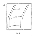
- FIG. 2 there is a fragmentary portion of the upper portion 26 as laid out flat.
- This fragmentary portion shows the two guides 30 having the lower parts 32 and the upper parts 34.
- Each lower part 32 is substantially straight and runs longitudinally with respect to the member 26.
- Each upper part 34 is curved through approximately 90 degrees laterally with respect to the upper member 26.
- the outer dimension of the collar 56 is less than the inner dimension of the tubular member 102 so that the tubular member 102 will slip over the collar 56.
- Figure 3 there is illustrated the assembly of the tubular support 20, the inner rotatable follower 50 inside of the upper portion 26 and the outer rotatable follower 100 positioned over the inner rotatable guide follower 50 and, naturally, over the upper portion 26.
- the relative positions of the electric motor 58 and the gearbox 62 and the screw 70 are illustrated.
- the relative positions of the outer rotatabl e follower 100 and the tubular support 20 are illustrated.
- the relative positions of the inner rotatable guide follower 50, the tubular support 20 and the outer rotatable follower 100 are illustrated.
- FIG 4 there is illustrated the outer rotatable follower 100 in a lowered position on the tubular support 20.
- the lower edge of the tubular member 102 is positioned close to the upper edge of the stop 28.
- the outer rotatable follower 100 is elevated with respect to the tubular support 20.
- the lower edge of the tubular member 102 is positioned above and spaced apart from the upper edge of the stop 28.
- the pin assembly 80 is a guide follower in the slots 30.
- Figures 6 and 7 there is illustrated an embodiment of the gate assembly.
- Figure 6 is an elevational view and Figure 7 is a plan view.
- FIG 6 it seen that the tubular support 20 is supported upright in the ground 118. Also, there is positioned in a spaced apart relationship with the tubular support 20 an upright latching post 120 comprising a tubular member 122. The tubular member 122 is also supported in the ground 118. There is positioned on the tubular member 122 a latch 124. The latch has a base clamp 126. On the outer part of the base clamp 126 there is an outwardly and upwardly directed flange 128. The flange 128 is spaced apart from the exterior of the tubular member 122. In Figure 7 it is seen that there is a semicircular strap 130. Strap 130 has threaded ends 132 as seen in Figure 6.
- the base clamp 126 there are two spaced apart holes or passageways. The ends of the threaded ends 132 project through these holes or passageways. Nuts 134 are screwed onto the threaded ends 132 to position the latch 124 firmly and definitely on the tubular member 122 of the latching post 120.
- a gate 140 comprising two spaced upright stiles 141 and 142.
- An upper bracket 160 is positioned on the outer rotatable follower 100.
- the bracket 160 comprises a clamp 162.
- Fasteners 164 connect the clamp 162 and the upright stile 141.
- a strap having threaded ends 168 wraps partially around the outer rotatable follower 100.
- Nuts 170 are screwed onto the threaded ends 168, outside of the clamp 162, to attach the bracket 160 firmly to the outer rotatable follower 100.
- the lower end of the tubular support and guide 20 can be positioned in concrete 176 for stability.
- an integral gate assembly comprising the tubular support 20, the inner moveable guide follower 50 and the outer rotatable follower 100 and the latching post 120.
- a brace 180 connect with the lower ends of the tubular support 20 and the lower end of the latching post tubular member 122 below the ground level. The result is an integral gate assembly.
- the gate assembly can be prepared, including the gate 140, at a factory. Then the gate assembly can be transported to the site of usage.
- the electric motor can be activated to retract the actuating screw into its housing.
- the gate 140 rotates through 90 degrees, the bar 146 is positioned adjacent to the tubular member 122, then, with the pin assembly moving downwardly in the lower parts 32 of the guide slots 30, the bar 146 will move downwardly so as to fit between the tubular member 122 and the flange 128. In this manner the gate 140 is locked into position.
- FIG 8 there is illustrated another gate assembly. Again, there is the tubular support 20, the outer rotatable follower 100 and the inner moveable guide follower. There is the latching post 120. Instead of the gate 140 comprising stiles and rails there is a gate bar 190. There is a bottom clamp 160 below the bar 190 to connect with the outer rotatable follower 100. There is a semicircular strap having threaded ends 168. The threaded ends 168 project through passageways in the clamp 160 and are attached by nuts 170 to the clamp. This definitely positions the clamp 160 on the outer rotatable follower 100. A diagonal brace 191 connects the clamp 160 with the bar 190.
- the bar connects with the outer rotatable follower 100 by means of a top semicircular strap having threaded ends 168.
- the threaded ends 168 project through openings or holes in the bar 190.
- FIG. 7 and 8 there is illustrated an automobile 190 having an occupant 192.
- the occupant 192 is holding a transmitter 194 for opening and closing the gate 140 or 190. In this manner the occupant does not have to get out of the automobile to open and close the gate.
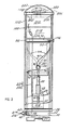
- FIG 9 there is a schematic illustration of the control unit for operating the gate assembly. There is illustrated the direct current electric motor 58, output shaft 60, gearbox 62 and screw housing 68.
- a housing 200 having a circular wall 202 and a bottom wall 204. On the upper part of the circular wall 202 there is a circumscribing lip 206. In the circular wall 202 there are passageways or holes 208. In the housing 200 there is the control unit 210.
- the housing 200 is plastic and a dielectric.
- Electric power lines 214 and 216 connect the commercial generator 212 and the control unit 210.
- the lines 214 and 216 pass through the passageways 208. With reference to Figures 1 and 3, such power lines can extend through the nipple 42 and the lower portion 22 of the support 20.
- the battery 218 can be 12 volts DC.
- the battery 218 is connected to the control unit 210.
- the antenna 220 can be positioned inside the plastic cap 108 as seen in Figure 3.
- the electric light bulb 222 is also positioned inside of the plastic cap 108.
- Electric lines 224 and 226 connect the direct current electric motor 58 with the control unit 210.
- the direct current electric motor 58 can be a 12 volt DC motor.
- the control uni t 210 controls the activation of the electric motor 58 and thereby the gearbox 62, the screw housing 68 and the screw 70 for elevating and for lowering the screw 70.
- the control unit 210 can adjust the voltage of the commercial generator 212 from say 120 or 240 volts AC to 12 volts DC.
- the 12 volt direct current battery 218 can be used for activating the electric motor 58.
- control unit 212 controls the electric light bulb 222.
- antenna 220 which connects with the control unit 210.
- the control unit 212 can have a battery charger for maintaining the electric charge on the battery 218.
- the primary source of electrical energy will be the commercial generator 212. If the commercial generator 212 fails or is not available then there is a backup source of electrical energy.
- the backup source of electrical energy is the battery 218.
- both the commercial generator 212 and the battery 218 are not available it will be necessary to move the gate 140 or the gate 190 manually.
- the bolt 106 is removed so that the outer rotatable follower 100 is no longer connected with the inner rotatable guide follower 50.
- With the removal of the bolt 106 it is possible for a person to lift the gate 140 or 190 and to rotate the outer rotatable follower 100 and the associated gate. In this manner, even though there is a failure in the electrical power supply 212 and 218 the gate 140 or 190 can be rotated so as to open the area for passage of an automobile vehicle or an individual or another object.
Landscapes
- Gates (AREA)
- Power-Operated Mechanisms For Wings (AREA)
Abstract
Description
- The present invention relates to a swinging gate mounting and swing actuator.
- One form of a gate comprises a vertical gatepost, a gate and at least two hinges interconnecting the vertical gatepost and the gate. The gate swings around the vertical hinge axis. Sometimes, there are two vertical gateposts and two gates which cooperate to close the space between the gateposts.
- Some gate assemblies which have a horizontal axis rotate vertically around the horizontal axis. Generally, there will be a counterweight or spring to assist in the vertical rotation of the gate around the horizontal axis.
- In certain instances there is a vertical gatepost. A heavy metal tube is hinged to the vertical gatepost and the gate swings horizontally around the vertical gatepost. Some of these gates are used in restricted areas such as on logging roads, construction projects and the like.
- A person in an automotive vehicle wanting to pass through the passageway closed by the gate must stop the automotive vehicle, get out and open the gate manually. Then after driving the vehicle through the passageway the gate must be closed.
- Some gates, particularly garage doors, are powered by a power means enabling them to be opened and closed by remote control.
- Ries U.S. patent No. 3,839,826, issued October 8, 1974, discloses a gate 14 mounted on a gatepost 4 to swing vertically around a horizontal axis 16. A
horizontal output shaft 24 of a gear andmotor combination 26 swings the gate 14.Radio receiver 66 controls the motor andgear combination 26 for actuating the gate. - In Tieben U.S. patent No. 4,231,190, issued November 4, 1980, a gate 14 is mounted by hinges 16 and 18 on a vertical gatepost 10 to swing horizontally about the vertical axis of the hinges. A
drive sprocket 62 is mounted on the end of the output shaft of a reversibleelectric motor 64. There are idler sprockets and a chain 76 extends around the drive sprocket and idler sprockets. A radio-controlledrelay 68 enables the gate to swing in one direction to open the passageway and to swing in the opposite direction to close the passageway. - In Courtis et al. U.S. patent No. 4,270,312, issued June 2, 1981, a gate 12 is mounted on a support means 11 and a lower horizontal pivot means 18. A chain 33 interconnects a
sprocket 34 on the upper part of the gate and gate-swinging means 14 controlled by a radio transmitter for raising the gate 12 to open the passageway and for lowering the gate to close the passageway. - Richmond U.S. patent No. 4,403,449, issued September 3, 1983, shows a gate 10 mounted on a vertical gatepost 12. Two
lever arms drive arm 38 is connected to thelever arm 40. Rotation of aworm gear 70 moves thearms - Wanzl U.S. patent No. 4,472,908, issued September 25, 1984, discloses a vertical gatepost 10 having a cylindrical base part 12. A cylindrical metal portion 14 carries a C-shaped gate 5. The rotary output shaft 17 is of a reversible squirrel cage motor 16 connected to the cylindrical middle portion 13. Activation of an electric eye sensor arrangement 6 controls the reversible motor 16 to rotate the middle portion 13 for opening and closing the passageway.
- This invention is directed to a swinging gate mounting and swing actuator mechanism which includes an upright tubular support having a guide, an inner rotatable guide follower and an outer rotatable follower on which a gate is mounted. Such mechanism simultaneously swings the gate horizontally about an upright axis and moves the gate elevationally. The tubular support supports the other components of the gate mounting and the gate. The inner rotatable guide foll ower is mainly inside of the tubular support and can move and rotate inside of the tubular support. The outer rotatable follower is on the outside of the tubular support and can move and rotate with respect to the tubular support. The outer rotatable follower is connected to the inner rotatable guide follower to form an integral unit. Power means can be used to swing the gate horizontally and also move the gate elevationally. A radio receiver receives radio signals from a transmitter in an automobile to actuate the power means to the gate. After the automobile has driven through the gate-controlled passage, the transmitter can be activated to send a signal to the radio receiver to close the gate.
- The preferred ways of carrying out the invention are described in detail below with reference to drawings which illustrate specific embodiments, in which:
- Figure 1 is an exploded elevation of some of the main components of the gate assembly and, in particular, a tubular support having a guide, an inner rotatable guide follower and an outer rotatable follower,
- Figure 2 is a fragmentary side elevation of the tubular support which has been developed onto a flat surface from a cylinder,
- Figure 3 is an elevation of most of the components of the gate assembly, viz., tubular support, inner rotatable guide follower and outer rotatable follower, with parts broken away,
- Figure 4 is a side elevation of the outer rotatable follower slidable on the tubular support in a lowered position, and Figure 5 is a similar view with the outer rotatable follower in an elevated position,
- Figure 6 is an elevation of the gate assembly with the gatepost comprising the tubular support, the inner rotatable guide follower, the outer rotatable follower, and the latching post in solid lines and a gate in phantom lines between the latching post and the tubular support,
- Figure 7 is a top plan of the gate assembly showing the gate in an open position and also in a closed position in broken lines and illustrates the outer rotatable follower, the gate and the latching post,
- Figure 8 is an elevation of another species of the gate assembly and illustrates the tubular support, the outer rotatable follower in a lowered position on the tubular support, a gate bar attached to the outer rotatable follower and a latching post, and
- Figure 9 is a schematic illustration of the control unit and its circuit diagram.
- Three of the main components of the gate assembly are the upright
tubular support 20 having aguide 30, the innerrotatable guide follower 50 and the outerrotatable follower 100. These are illustrated in Figure 1. - The
tubular support 20 can be considered as comprising alower portion 22 having anotch 24 in the lower end and anupper portion 26. Astop ring 28 is welded below the middle part of the tubular support. Thestop ring 28 designates the ground level for thetubular support 20. - In the upper part of the
upper portion 26 it is seen that there are twoguides 30 in the form of two diametrically opposed slots. Each of theguides 30 has alower part 32 and anupper part 34. Thelower part 32 is substantially vertical and theupper part 34 curves helically upward and circumferentially. In Figure 1 the solidupper part 34 curves to the right and the phantomupper part 34 curves to the left. In theupper support portion 26 it is seen that there are a plurality of holes orpassageways 36 for receivingtrunnion pins 66. Below theholes 36 and below thestop 38 there is a tappedhole 38 for receiving a threadednipple 42. Awasher 40 is positioned between thelower portion 22 and the outer head of thenipple 42. - The inner
rotatable guide follower 50 comprises atubular member 52. In thetubular member 52 there are two alignedholes 54. On top of thetubular member 52 there is acollar 56. In thecollar 56 there is a tappedrecess 92. In the tubular member 52, and below theholes 54, there are two aligned holes 57. - The external dimension of the
tubular member 52 is smaller than the internal dimension of theupper portion 26 of thesupport 20. This makes it possible for thetubular member 52 to move and to rotate in theupper member 26. It is to be clearly understood that most of thetubular member 52 is positioned in theupper support portion 26 and thetubular member 52 moves and rotates inside of suchupper portion 26. - The outer dimension of the
collar 56 is greater than the inner dimension of theupper support portion 26. As a result, thecollar 56 can rest on the top of theupper portion 26. In practice, the outer dimension of thecollar 56 may be greater than the outer dimension of theupper portion 26 to insure that thecollar 56 rests on the top of theupper portion 26 so as to limit the penetration of thetubular member 52 into theupper portion 26. - In Figure 1 it is seen that there is an
electric motor 58 having anoutput shaft 60. Theoutput shaft 60 connects with agearbox 62. In thegearbox 62 are a plurality of tapped holes 64. Theelectric motor 58 and thegearbox 62 are positioned in thelower portion 22 ofsupport 20. A number of trunnion pins 66 are positioned in the holes orpassageways 36 and also in the tappedholes 64 so as to definitely position thegearbox 62 with respect to theupper portion 26. Consequently, thegearbox 62 cannot rotate with respect to thelower portion 22. Further, theelectric motor 58 and thegearbox 62 can be in a common housing so that theelectric motor 58 and thegearbox 62 do not rotate or move with respect to each other. Thegearbox 62 connects with thescrew housing 68. In thescrew housing 68 there is ascrew 70. On the upper part of thescrew 70 there is a spacer or atorus 72. There is on the upper part of thescrew 70 aneye 74. Theeye 74 has ahole 78 for receiving apin 81. Thepin 81 is in thehole 78 and the two passageways 57 in theinner guide follower 50. - There is a
pin assembly 80 comprising a pipe or asleeve 82. There is positioned in one end of the sleeve 82 afirst rod 84. A bearing 86 surrounds thefirst rod 84 and is positioned near thesleeve 82. There is also positioned in the sleeve 82 asecond rod 88. Asecond bearing 90 surrounds thesecond rod 88 and is positioned near thesleeve 82. - It is to be recalled that in the
tubular member 52 there are two alignedholes 54. Thepin assembly 80 is positioned in the two alignedholes 54 with a bearing in each hole. Thepin assembly 80 is also positioned in the twoguide slots 30 with thefirst rod 84 in one of the slots and thesecond rod 88 in the opposite slot. Further, it is to be recalled that thegearbox 62 is positioned in theupper portion 26 and cannot rotate. With the actuation of theelectric motor 58, thescrew housing 68 is rotated and thescrew 70 either elevated or lowered. With thepin 81 in thehole 78 and in the holes 57 of thetubular member 52 and thepin assembly 80 in the twoguide slots 30 of theupper portion 26 and in theholes 54 of the innerrotatable guide follower 50 thefollower 50 is moved elevationally and rotated. If thescrew 70 is moved outwardly of thescrew housing 68 then thepin assembly 80 moves first upwardly in thelower parts 32 of theguide slots 30 and then upwardly and horizontally in the curvedupper parts 34. As a result of the movement of thepin assembly 80 in theguide slots 30 the innerrotatable guide follower 50 also moves upwardly and also rotates horizontally with the movement of thepin assembly 80 in the uppercurved parts 34 of theguide slots 30. Conversely, with thescrew 70 being retracted into thescrew housing 68 thepin assembly 80 first moves downwardly in theupper parts 34 of theguide slots 30 so as to rotate in the uppercurved parts 34. Likewise, the innerrotatable guide follower 50 moves downwardly and rotates inside of theupper portion 26. With thepin assembly 80 moving downwardly in t helower parts 32 of theguide slots 30 the innerrotatable guide follower 50 moves downwardly in theupper support portion 26. - From the foregoing discussion it is seen that the inner
rotatable guide follower 50 moves longitudinally in theupper portion 26 or vertically in theupper portion 26 when thepin assembly 80 is in thelower parts 32 of the guide slots and rotates inside of theupper portion 26 when thepin assembly 80 is in theupper slot parts 34. - The
guide slots 30 are curved through approximately 90 degrees horizontally. With the movement of the innerrotatable guide follower 50 following the movement of thepin assembly 80 in theupper parts 34 of theguide slots 30, the innerrotatable guide follower 50 rotates through 90 degrees horizontally. - The outer
rotatable follower 100 comprises atubular member 102. In the upper part of thetubular member 102 there is a tappedpassageway 104. Abolt 106 extends through the tappedpassageway 104 and into the tappedrecess 92 so as to unite the innerrotatable guide follower 50 and the outerrotatable follower 100. With the movement of the innerrotatable guide follower 50 the outerrotatable follower 100 will likewise move conjointly. There is positioned on top of the tubular member 102 acap 108. Thecap 108 can be a plastic cap and can be translucent. Theplastic cap 108 seals the top of thetubular member 102 to keep out moisture and debris. - The inner dimension of the
tubular member 102 is greater than the outer dimension of theupper portion 26 ofsupport 20. Therefore, thetubular member 102 can move and can rotate relative to suchupper portion 26. - With the movement of the inner
rotatable guide follower 50, both longitudinally and rotationally, relative to thetubular support 20, the outerrotatable follower 100 also moves both longitudinally and rotationally relative to thetubular support 20. - With the attaching of a gate onto the
tubular member 102 the gate will both move elevationally and rotate. Since theupper parts 34 of theguide slots 30 extend through 90 degrees horizontally, thetubular member 102 will swing 90 degrees horizontally and the gate will also swing 90 degrees horizontally. - In Figure 2 there is a fragmentary portion of the
upper portion 26 as laid out flat. This fragmentary portion shows the twoguides 30 having thelower parts 32 and theupper parts 34. Eachlower part 32 is substantially straight and runs longitudinally with respect to themember 26. Eachupper part 34 is curved through approximately 90 degrees laterally with respect to theupper member 26. - In Figure 2 it is seen that with the
pin assembly 80 in thelower parts 32, thepin assembly 80 will follow thelower parts 32 to elevate the innerrotatable guide follower 50 and to elevate simultaneously the outerrotatable follower 100. With thepin assembly 80 in theupper parts 34, the pin assembly will follow the curvedupper parts 34 and elevate longitudinally and, simultaneously, swing laterally through about 90 degrees the innerrotatable guide follower 50 and the outerrotatable follower 100. In effect, the innerrotatable guide follower 50 and the outerrotatable follower 100 are elevated and rotated while moving upwardly in theguide slots 30 and, conversely, are lowered and rotated while moving downwardly in theguide slots 30. - Naturally, the outer dimension of the
collar 56 is less than the inner dimension of thetubular member 102 so that thetubular member 102 will slip over thecollar 56. - In Figure 3 there is illustrated the assembly of the
tubular support 20, the innerrotatable follower 50 inside of theupper portion 26 and the outerrotatable follower 100 positioned over the innerrotatable guide follower 50 and, naturally, over theupper portion 26. The relative positions of theelectric motor 58 and thegearbox 62 and thescrew 70 are illustrated. Further, the relative positions of the outer rotatabl efollower 100 and thetubular support 20 are illustrated. Finally, the relative positions of the innerrotatable guide follower 50, thetubular support 20 and the outerrotatable follower 100 are illustrated. - In Figure 4 there is illustrated the outer
rotatable follower 100 in a lowered position on thetubular support 20. In fact, the lower edge of thetubular member 102 is positioned close to the upper edge of thestop 28. - In Figure 5 the outer
rotatable follower 100 is elevated with respect to thetubular support 20. The lower edge of thetubular member 102 is positioned above and spaced apart from the upper edge of thestop 28. - The
pin assembly 80 is a guide follower in theslots 30. - In Figures 6 and 7 there is illustrated an embodiment of the gate assembly. Figure 6 is an elevational view and Figure 7 is a plan view.
- In Figure 6 is it seen that the
tubular support 20 is supported upright in theground 118. Also, there is positioned in a spaced apart relationship with thetubular support 20 anupright latching post 120 comprising atubular member 122. Thetubular member 122 is also supported in theground 118. There is positioned on the tubular member 122 alatch 124. The latch has abase clamp 126. On the outer part of thebase clamp 126 there is an outwardly and upwardly directedflange 128. Theflange 128 is spaced apart from the exterior of thetubular member 122. In Figure 7 it is seen that there is asemicircular strap 130.Strap 130 has threaded ends 132 as seen in Figure 6. In thebase clamp 126 there are two spaced apart holes or passageways. The ends of the threaded ends 132 project through these holes or passageways.Nuts 134 are screwed onto the threaded ends 132 to position thelatch 124 firmly and definitely on thetubular member 122 of the latchingpost 120. - There is a
gate 140 comprising two spacedupright stiles horizontal rails 144 connecting with thestiles - On the
stile 142 it is seen that there is abar 146. Thestile 142 and thebar 146 are connected byfasteners 148. - It is seen that there is positioned on the
tubular support 20 the outerrotatable follower 100. Also, it is seen that thestop 28 is at theground level 150. Anupper bracket 160 is positioned on the outerrotatable follower 100. Thebracket 160 comprises aclamp 162.Fasteners 164 connect theclamp 162 and theupright stile 141. A strap having threaded ends 168 wraps partially around the outerrotatable follower 100. In theclamp 162 there are two spaced apart holes or passageways, one at each side of the outerrotatable follower 100.Nuts 170 are screwed onto the threaded ends 168, outside of theclamp 162, to attach thebracket 160 firmly to the outerrotatable follower 100. In Figure 6 it is seen that there is alower bracket 160 identical to theupper bracket 160. - In Figure 6 it is seen that in the upper portion of the
tubular support 20 that there are theguide slots 30. Each slot has the verticallower part 32. Again, the pin assembly is positioned so that parts of the pin assembly are in the twoguide slots 30. - The lower end of the tubular support and guide 20 can be positioned in
concrete 176 for stability. - Further, in certain instances it may be desirable to have an integral gate assembly comprising the
tubular support 20, the innermoveable guide follower 50 and the outerrotatable follower 100 and the latchingpost 120. To achieve this it is possible to have abrace 180 connect with the lower ends of thetubular support 20 and the lower end of the latchingpost tubular member 122 below the ground level. The result is an integral gate assembly. The gate assembly can be prepared, including thegate 140, at a factory. Then the gate assembly can be transported to the site of usage. - In Figure 6 it is seen that with, the rising or elevation of the screw connected to the pin assembly, the
latch bar 146 rises vertically and upwardly so as to be freed from theflange 128 oflatch 124. After thebar 146 is moved upwardly and away from theflange 128 the pin assembly enters thecurved parts 34 of theguide slots 30 and still moves upwardly and also rotates through approximately 90 degrees so that thegate 140 rotates through approximately 90 degrees (see Figure 7). - Conversely, to rotate the
gate 140 and to lower thegate 140 and to have thebar 146 received in thelatch 124, the electric motor can be activated to retract the actuating screw into its housing. With the downward movement in the curvedupper parts 34 thegate 140 rotates through 90 degrees, thebar 146 is positioned adjacent to thetubular member 122, then, with the pin assembly moving downwardly in thelower parts 32 of theguide slots 30, thebar 146 will move downwardly so as to fit between thetubular member 122 and theflange 128. In this manner thegate 140 is locked into position. - In Figure 8 there is illustrated another gate assembly. Again, there is the
tubular support 20, the outerrotatable follower 100 and the inner moveable guide follower. There is the latchingpost 120. Instead of thegate 140 comprising stiles and rails there is agate bar 190. There is abottom clamp 160 below thebar 190 to connect with the outerrotatable follower 100. There is a semicircular strap having threaded ends 168. The threaded ends 168 project through passageways in theclamp 160 and are attached bynuts 170 to the clamp. This definitely positions theclamp 160 on the outerrotatable follower 100. Adiagonal brace 191 connects theclamp 160 with thebar 190. The bar connects with the outerrotatable follower 100 by means of a top semicircular strap having threaded ends 168. The threaded ends 168 project through openings or holes in thebar 190. There are nuts 170 on the threaded ends 168 to clamp the strap and gate bar to thetubular member 100. On the latchingpost 120 there is alatch assembly 124. In operation, thebar 190 is elevated and rotated away from the latchingpost 120 as described with reference to Figures 6 and 7. - In each of Figures 7 and 8 there is illustrated an
automobile 190 having anoccupant 192. Theoccupant 192 is holding atransmitter 194 for opening and closing thegate - In Figure 9 there is a schematic illustration of the control unit for operating the gate assembly. There is illustrated the direct current
electric motor 58,output shaft 60,gearbox 62 and screwhousing 68. - There is a
housing 200 having acircular wall 202 and abottom wall 204. On the upper part of thecircular wall 202 there is a circumscribinglip 206. In thecircular wall 202 there are passageways or holes 208. In thehousing 200 there is thecontrol unit 210. Thehousing 200 is plastic and a dielectric. - There is a
commercial generator 212 for supplying alternating current such as 110 volts AC, 220 AC or 440 volts AC.Electric power lines commercial generator 212 and thecontrol unit 210. Thelines passageways 208. With reference to Figures 1 and 3, such power lines can extend through thenipple 42 and thelower portion 22 of thesupport 20. - Returning to Figure 9, there is a
battery 218. Thebattery 218 can be 12 volts DC. Thebattery 218 is connected to thecontrol unit 210. There is anantenna 220 connected to thecontrol unit 210. Theantenna 220 can be positioned inside theplastic cap 108 as seen in Figure 3. There is an electriclight bulb 222 which connects with thecontrol unit 210. The electriclight bulb 222 is also positioned inside of theplastic cap 108.Electric lines electric motor 58 with thecontrol unit 210. - The direct current
electric motor 58 can be a 12 volt DC motor. Thecontrol uni t 210 controls the activation of theelectric motor 58 and thereby thegearbox 62, thescrew housing 68 and thescrew 70 for elevating and for lowering thescrew 70. As previously explained, with the elevation and the lowering of thescrew 70 the position of the outerrotatable follower 100 is changed to elevate and to lower thegate gate control unit 210 can adjust the voltage of thecommercial generator 212 fromsay 120 or 240 volts AC to 12 volts DC. As a backup source of electrical energy, in case thecommercial generator 212 is not available, the 12 volt directcurrent battery 218 can be used for activating theelectric motor 58. Further, thecontrol unit 212 controls the electriclight bulb 222. There is anantenna 220 which connects with thecontrol unit 210. Theoccupant 192 of theautomotive vehicle 190 by means of thetransmitter 194, shown in Figures 6 and 7, can send electromagnetic wave signals to theantenna 220 to control theelectric motor 58. Further, thecontrol unit 212 can have a battery charger for maintaining the electric charge on thebattery 218. - Generally, the primary source of electrical energy will be the
commercial generator 212. If thecommercial generator 212 fails or is not available then there is a backup source of electrical energy. The backup source of electrical energy is thebattery 218. - If both the
commercial generator 212 and thebattery 218 are not available it will be necessary to move thegate 140 or thegate 190 manually. In order to do this thebolt 106 is removed so that the outerrotatable follower 100 is no longer connected with the innerrotatable guide follower 50. With the removal of thebolt 106 it is possible for a person to lift thegate rotatable follower 100 and the associated gate. In this manner, even though there is a failure in theelectrical power supply gate
Claims (9)
an upright tubular support (20) having a guide (30);
an inner member (50) having a portion (52) thereof received within said tubular support (20) and rotatable relative thereto;
a gate (140, 190);
an outer tubular gate-supporting member (100) receiving a portion (26) of said tubular support (20) therein and connected to said member (50) for conjoint rotation relative to said support (20), at least one of said members (50, 100) having a follower (80) cooperating with said guide (30) for guiding said inner member (50) and said outer member (100) relative to said support (20); and
power means (58, 60, 62, 68, 70) operatively connected to one of said members (50, 100) for driving said members (50, 100) relative to said support (20).
Applications Claiming Priority (2)
| Application Number | Priority Date | Filing Date | Title |
|---|---|---|---|
| US06/861,833 US4665650A (en) | 1986-05-12 | 1986-05-12 | Control gate assembly |
| US861833 | 1986-05-12 |
Publications (2)
| Publication Number | Publication Date |
|---|---|
| EP0246033A2 true EP0246033A2 (en) | 1987-11-19 |
| EP0246033A3 EP0246033A3 (en) | 1988-03-23 |
Family
ID=25336891
Family Applications (1)
| Application Number | Title | Priority Date | Filing Date |
|---|---|---|---|
| EP87304088A Withdrawn EP0246033A3 (en) | 1986-05-12 | 1987-05-07 | Swinging gate mounting and swing actuator |
Country Status (3)
| Country | Link |
|---|---|
| US (1) | US4665650A (en) |
| EP (1) | EP0246033A3 (en) |
| CA (1) | CA1271351A (en) |
Cited By (3)
| Publication number | Priority date | Publication date | Assignee | Title |
|---|---|---|---|---|
| EP0581982A1 (en) * | 1991-02-21 | 1994-02-09 | Brüder Siegel GmbH + Co. KG Draht- und Metallwarenfabrik | Pivoting gate for clients' passage |
| FR2707695A1 (en) * | 1993-06-30 | 1995-01-20 | Horizal | Door having motorised opening and closing movements |
| ITFI20100003A1 (en) * | 2010-01-11 | 2011-07-12 | Antonio Mazzantini | DOOR WITH DESMODROMIC RETURN. |
Families Citing this family (32)
| Publication number | Priority date | Publication date | Assignee | Title |
|---|---|---|---|---|
| JPS6138359U (en) * | 1984-08-10 | 1986-03-10 | 大阪機器製造株式会社 | Valve opening/closing drive mechanism |
| US4916859A (en) * | 1985-07-02 | 1990-04-17 | Embassy Gate Associates, L.P. | Assault-resistant gate |
| US5035082A (en) * | 1985-07-02 | 1991-07-30 | Embassy Gates Associates, L.P. | Gate support and operating mechanism |
| US4828361A (en) * | 1987-08-26 | 1989-05-09 | Siegel-Robert, Inc. | Semi-automatic rear view mirror assembly |
| US4934203A (en) * | 1989-01-06 | 1990-06-19 | Bailey Thomas R | Power arm |
| TW371705B (en) * | 1997-04-09 | 1999-10-11 | Nikkiso Co Ltd | Stroke length adjustment device |
| IT237536Y1 (en) * | 1997-05-30 | 2000-09-13 | Campisa Srl | SECTIONAL DOOR PERFECTED |
| IT237541Y1 (en) * | 1997-06-03 | 2000-09-13 | Campisa Srl | PERFECTED MOTORIZED GATE |
| US6179517B1 (en) * | 1999-07-22 | 2001-01-30 | Kim L. Nelson | Traffic access control system |
| DE10202826B4 (en) * | 2002-01-24 | 2005-05-04 | Wittenstein Motion Control Gmbh | Device for actuating doors of vehicles |
| ITMI20032159A1 (en) * | 2003-11-10 | 2005-05-11 | Fin Men S P A | AUTOMATIC GATE MOVEMENT SYSTEM |
| WO2005073494A1 (en) * | 2004-01-16 | 2005-08-11 | Stull Edward J | Balanced gate mechanism |
| WO2005079473A2 (en) * | 2004-02-19 | 2005-09-01 | Logical Decisions, Inc. | Automatic lift and turn hinge and gate |
| US7367161B1 (en) | 2004-04-30 | 2008-05-06 | Michael Wayne Jones | Gate opening and closing apparatus |
| WO2007112388A2 (en) * | 2006-03-27 | 2007-10-04 | Stull Edward J | Gate support device |
| US8296998B2 (en) * | 2006-03-27 | 2012-10-30 | Turnstyle Intellectual Property, Llc | Powered actuator |
| US7506860B2 (en) * | 2006-04-07 | 2009-03-24 | Turnstyle Intellectual Property, Llc | Temporary gate support device |
| US20080237561A1 (en) * | 2006-10-25 | 2008-10-02 | 440 Fence Company, Inc. | Hingeless fence |
| BE1017519A6 (en) * | 2007-03-22 | 2008-11-04 | Meersman Bvba | AUTOMATIC HINGE FOR DOORS, GATES, GATES E.D. |
| WO2008157301A1 (en) * | 2007-06-15 | 2008-12-24 | Turnstyle Intellectual Property, Llc. | Dual swing powered gate actuator |
| US20100319262A1 (en) * | 2008-01-30 | 2010-12-23 | Stull Edward J | Powered gate |
| ITBS20080087A1 (en) * | 2008-04-22 | 2009-10-23 | Colse S R L | PAIR OF PRECABLATE PLANTS FOR SLIDING OR SWING GATES |
| US8341888B2 (en) * | 2008-07-23 | 2013-01-01 | Turnstyle Intellectual Property, Llc | Enclosed powered gate post |
| US20110197526A1 (en) * | 2010-02-17 | 2011-08-18 | Charles Frederick Thomas | Adjustable pillar |
| US8534005B2 (en) | 2010-02-17 | 2013-09-17 | Charles Frederick Thomas | Adjustable and reversible pillar |
| USD665436S1 (en) * | 2011-02-10 | 2012-08-14 | Advantage Gate Products Inc. | Gate operator |
| US9145724B2 (en) * | 2014-03-30 | 2015-09-29 | David Edmond Dudley | Floor-mounting gate-closer post with rotary dampener |
| US9945122B2 (en) * | 2016-01-25 | 2018-04-17 | IGC Gate Components Inc. | Pillar assembly |
| CH717738B1 (en) * | 2020-08-13 | 2025-05-15 | Eymannwerks Gmbh | Automatically closing gate. |
| US11649675B2 (en) * | 2021-03-17 | 2023-05-16 | Troy Hinojosa | Gate opener assembly |
| US12139953B2 (en) * | 2021-05-04 | 2024-11-12 | San Francisco Bay Area Rapid Transit District | Pneumatic fare gate |
| USD1051433S1 (en) * | 2023-03-03 | 2024-11-12 | Robert Farrell | Protective barrier pole |
Family Cites Families (15)
| Publication number | Priority date | Publication date | Assignee | Title |
|---|---|---|---|---|
| US2883183A (en) * | 1958-04-21 | 1959-04-21 | Gen Motors Corp | Vehicle window actuators |
| FR1493072A (en) * | 1966-07-13 | 1967-08-25 | Device for the automatic remote control of the opening and closing of a flexible door | |
| SE322144B (en) * | 1969-05-23 | 1970-03-23 | Gunnar Fredrikson Ab | |
| US3829826A (en) * | 1972-08-22 | 1974-08-13 | Hewlett Packard Co | Cable fastener for electrocardiograph electrodes |
| GB1534291A (en) * | 1976-03-15 | 1978-11-29 | Dunlop Ltd | Vehicle door-operating devices |
| US4231190A (en) * | 1978-10-04 | 1980-11-04 | My-D-Han-D Manufacturing Co. | Remotely controlled gate opener |
| US4270312A (en) * | 1979-10-09 | 1981-06-02 | Red Lodge Manufacturing Company | Gate assembly |
| US4403449A (en) * | 1980-03-03 | 1983-09-13 | Richmond Moscow K | Gate-opening and closing apparatus and method |
| DE3021114A1 (en) * | 1980-06-04 | 1981-12-17 | Rudolf Wanzl Kg, 8874 Leipheim | Pivoted door for self-service shops - has energy store accommodating residual energy of spindle after motor has been switched off |
| FR2485075A1 (en) * | 1980-06-18 | 1981-12-24 | Faivre Robert | Opening and closing actuator for gate - has hydraulic cylinder to simultaneously lift and pivot gate via slide |
| DE3121136A1 (en) * | 1981-05-27 | 1982-12-16 | Magnetic-Elektromotoren GmbH, 7867 Maulburg | Drive especially for up-and-over doors and the like |
| US4490941A (en) * | 1981-08-13 | 1985-01-01 | Vapor Corporation | Spindle door operator |
| DE3261555D1 (en) * | 1981-09-25 | 1985-01-24 | Wanzl Kg Rudolf | Pivoting gate equipment for passageways |
| DE3219192A1 (en) * | 1982-05-21 | 1983-11-24 | Erich 8263 Burghausen Unterreiter | Rotary drive, especially for doors, gates, cupboards or the like |
| CH651103A5 (en) * | 1983-12-19 | 1985-08-30 | Konrad Buchenberg | Gate or door with a pivoting drive |
-
1986
- 1986-05-12 US US06/861,833 patent/US4665650A/en not_active Expired - Fee Related
- 1986-12-30 CA CA000526541A patent/CA1271351A/en not_active Expired
-
1987
- 1987-05-07 EP EP87304088A patent/EP0246033A3/en not_active Withdrawn
Cited By (3)
| Publication number | Priority date | Publication date | Assignee | Title |
|---|---|---|---|---|
| EP0581982A1 (en) * | 1991-02-21 | 1994-02-09 | Brüder Siegel GmbH + Co. KG Draht- und Metallwarenfabrik | Pivoting gate for clients' passage |
| FR2707695A1 (en) * | 1993-06-30 | 1995-01-20 | Horizal | Door having motorised opening and closing movements |
| ITFI20100003A1 (en) * | 2010-01-11 | 2011-07-12 | Antonio Mazzantini | DOOR WITH DESMODROMIC RETURN. |
Also Published As
| Publication number | Publication date |
|---|---|
| US4665650A (en) | 1987-05-19 |
| EP0246033A3 (en) | 1988-03-23 |
| CA1271351A (en) | 1990-07-10 |
Similar Documents
| Publication | Publication Date | Title |
|---|---|---|
| EP0246033A2 (en) | Swinging gate mounting and swing actuator | |
| CA1198131A (en) | Integral device for garage door opener | |
| US4658543A (en) | Swinging lift gate | |
| EP0925417B1 (en) | Motorized operator for doors | |
| US6739372B2 (en) | Overhead door locking operator | |
| US8291643B2 (en) | Gate support device | |
| US4735018A (en) | Gate operator unit | |
| US5035082A (en) | Gate support and operating mechanism | |
| US20030196766A1 (en) | Overhead door locking operator | |
| US6176044B1 (en) | Underground door operating apparatus and method | |
| US20040098915A1 (en) | Residential handicap accessible door | |
| US2742280A (en) | Garage door operator with automatic latch | |
| CN212716284U (en) | An integrated electric window opening device | |
| CN206309202U (en) | A kind of multifunctional intellectual window | |
| GB2124296A (en) | Power operators for closure assemblies | |
| CN210817562U (en) | Intelligence accessories drilling equipment | |
| KR20220144485A (en) | Ladder type door that can be folded | |
| KR102722264B1 (en) | Automatic locking device for lift and general sliding windows | |
| US1738741A (en) | Automatic door operating and locking device | |
| CN111894399A (en) | From electronic storehouse door of taking opener | |
| CN222045475U (en) | A sliding door and window switch mechanism | |
| GB2396658A (en) | Automated door opener including pivoting lever or track mechanism | |
| CN219412650U (en) | Easy-open anti-pinch electric door device for mine ventilation tunnel | |
| CN220267482U (en) | Revolving door with adjustable rotation angle | |
| CN221343631U (en) | Well lid opening device for municipal construction |
Legal Events
| Date | Code | Title | Description |
|---|---|---|---|
| PUAI | Public reference made under article 153(3) epc to a published international application that has entered the european phase |
Free format text: ORIGINAL CODE: 0009012 |
|
| AK | Designated contracting states |
Kind code of ref document: A2 Designated state(s): CH DE ES FR GB IT LI SE |
|
| PUAL | Search report despatched |
Free format text: ORIGINAL CODE: 0009013 |
|
| AK | Designated contracting states |
Kind code of ref document: A3 Designated state(s): CH DE ES FR GB IT LI SE |
|
| 17P | Request for examination filed |
Effective date: 19880825 |
|
| 17Q | First examination report despatched |
Effective date: 19891016 |
|
| STAA | Information on the status of an ep patent application or granted ep patent |
Free format text: STATUS: THE APPLICATION IS DEEMED TO BE WITHDRAWN |
|
| 18D | Application deemed to be withdrawn |
Effective date: 19900227 |
|
| RIN1 | Information on inventor provided before grant (corrected) |
Inventor name: HALL, RICHARD C. |