JP5124559B2 - Gate support device - Google Patents
Gate support device Download PDFInfo
- Publication number
- JP5124559B2 JP5124559B2 JP2009503213A JP2009503213A JP5124559B2 JP 5124559 B2 JP5124559 B2 JP 5124559B2 JP 2009503213 A JP2009503213 A JP 2009503213A JP 2009503213 A JP2009503213 A JP 2009503213A JP 5124559 B2 JP5124559 B2 JP 5124559B2
- Authority
- JP
- Japan
- Prior art keywords
- post
- gate
- drive
- drive slot
- rotation
- Prior art date
- Legal status (The legal status is an assumption and is not a legal conclusion. Google has not performed a legal analysis and makes no representation as to the accuracy of the status listed.)
- Expired - Fee Related
Links
Images


Classifications
-
- E—FIXED CONSTRUCTIONS
- E06—DOORS, WINDOWS, SHUTTERS, OR ROLLER BLINDS IN GENERAL; LADDERS
- E06B—FIXED OR MOVABLE CLOSURES FOR OPENINGS IN BUILDINGS, VEHICLES, FENCES OR LIKE ENCLOSURES IN GENERAL, e.g. DOORS, WINDOWS, BLINDS, GATES
- E06B11/00—Means for allowing passage through fences, barriers or the like, e.g. stiles
- E06B11/02—Gates; Doors
-
- E—FIXED CONSTRUCTIONS
- E05—LOCKS; KEYS; WINDOW OR DOOR FITTINGS; SAFES
- E05F—DEVICES FOR MOVING WINGS INTO OPEN OR CLOSED POSITION; CHECKS FOR WINGS; WING FITTINGS NOT OTHERWISE PROVIDED FOR, CONCERNED WITH THE FUNCTIONING OF THE WING
- E05F15/00—Power-operated mechanisms for wings
- E05F15/60—Power-operated mechanisms for wings using electrical actuators
- E05F15/603—Power-operated mechanisms for wings using electrical actuators using rotary electromotors
- E05F15/611—Power-operated mechanisms for wings using electrical actuators using rotary electromotors for swinging wings
- E05F15/614—Power-operated mechanisms for wings using electrical actuators using rotary electromotors for swinging wings operated by meshing gear wheels, one of which being mounted at the wing pivot axis; operated by a motor acting directly on the wing pivot axis
-
- E—FIXED CONSTRUCTIONS
- E05—LOCKS; KEYS; WINDOW OR DOOR FITTINGS; SAFES
- E05F—DEVICES FOR MOVING WINGS INTO OPEN OR CLOSED POSITION; CHECKS FOR WINGS; WING FITTINGS NOT OTHERWISE PROVIDED FOR, CONCERNED WITH THE FUNCTIONING OF THE WING
- E05F15/00—Power-operated mechanisms for wings
- E05F15/60—Power-operated mechanisms for wings using electrical actuators
- E05F15/603—Power-operated mechanisms for wings using electrical actuators using rotary electromotors
- E05F15/611—Power-operated mechanisms for wings using electrical actuators using rotary electromotors for swinging wings
- E05F15/616—Power-operated mechanisms for wings using electrical actuators using rotary electromotors for swinging wings operated by push-pull mechanisms
- E05F15/622—Power-operated mechanisms for wings using electrical actuators using rotary electromotors for swinging wings operated by push-pull mechanisms using screw-and-nut mechanisms
-
- E—FIXED CONSTRUCTIONS
- E05—LOCKS; KEYS; WINDOW OR DOOR FITTINGS; SAFES
- E05Y—INDEXING SCHEME RELATING TO HINGES OR OTHER SUSPENSION DEVICES FOR DOORS, WINDOWS OR WINGS AND DEVICES FOR MOVING WINGS INTO OPEN OR CLOSED POSITION, CHECKS FOR WINGS AND WING FITTINGS NOT OTHERWISE PROVIDED FOR, CONCERNED WITH THE FUNCTIONING OF THE WING
- E05Y2201/00—Constructional elements; Accessories therefore
- E05Y2201/20—Brakes; Disengaging means, e.g. clutches; Holders, e.g. locks; Stops; Accessories therefore
- E05Y2201/214—Disengaging means
-
- E—FIXED CONSTRUCTIONS
- E05—LOCKS; KEYS; WINDOW OR DOOR FITTINGS; SAFES
- E05Y—INDEXING SCHEME RELATING TO HINGES OR OTHER SUSPENSION DEVICES FOR DOORS, WINDOWS OR WINGS AND DEVICES FOR MOVING WINGS INTO OPEN OR CLOSED POSITION, CHECKS FOR WINGS AND WING FITTINGS NOT OTHERWISE PROVIDED FOR, CONCERNED WITH THE FUNCTIONING OF THE WING
- E05Y2201/00—Constructional elements; Accessories therefore
- E05Y2201/20—Brakes; Disengaging means, e.g. clutches; Holders, e.g. locks; Stops; Accessories therefore
- E05Y2201/23—Actuation thereof
- E05Y2201/244—Actuation thereof by manual operation
-
- E—FIXED CONSTRUCTIONS
- E05—LOCKS; KEYS; WINDOW OR DOOR FITTINGS; SAFES
- E05Y—INDEXING SCHEME RELATING TO HINGES OR OTHER SUSPENSION DEVICES FOR DOORS, WINDOWS OR WINGS AND DEVICES FOR MOVING WINGS INTO OPEN OR CLOSED POSITION, CHECKS FOR WINGS AND WING FITTINGS NOT OTHERWISE PROVIDED FOR, CONCERNED WITH THE FUNCTIONING OF THE WING
- E05Y2201/00—Constructional elements; Accessories therefore
- E05Y2201/60—Suspension or transmission members; Accessories therefore
- E05Y2201/622—Suspension or transmission members elements
- E05Y2201/71—Toothed gearing
- E05Y2201/72—Planetary gearing
-
- E—FIXED CONSTRUCTIONS
- E05—LOCKS; KEYS; WINDOW OR DOOR FITTINGS; SAFES
- E05Y—INDEXING SCHEME RELATING TO HINGES OR OTHER SUSPENSION DEVICES FOR DOORS, WINDOWS OR WINGS AND DEVICES FOR MOVING WINGS INTO OPEN OR CLOSED POSITION, CHECKS FOR WINGS AND WING FITTINGS NOT OTHERWISE PROVIDED FOR, CONCERNED WITH THE FUNCTIONING OF THE WING
- E05Y2800/00—Details, accessories and auxiliary operations not otherwise provided for
- E05Y2800/352—Frames; Posts
- E05Y2800/36—Movable frames
- E05Y2800/364—Movable frames vertical frame members
-
- E—FIXED CONSTRUCTIONS
- E05—LOCKS; KEYS; WINDOW OR DOOR FITTINGS; SAFES
- E05Y—INDEXING SCHEME RELATING TO HINGES OR OTHER SUSPENSION DEVICES FOR DOORS, WINDOWS OR WINGS AND DEVICES FOR MOVING WINGS INTO OPEN OR CLOSED POSITION, CHECKS FOR WINGS AND WING FITTINGS NOT OTHERWISE PROVIDED FOR, CONCERNED WITH THE FUNCTIONING OF THE WING
- E05Y2900/00—Application of doors, windows, wings or fittings thereof
- E05Y2900/40—Application of doors, windows, wings or fittings thereof for gates
Landscapes
- Engineering & Computer Science (AREA)
- Civil Engineering (AREA)
- Structural Engineering (AREA)
- Gates (AREA)
- Power-Operated Mechanisms For Wings (AREA)
- Refuge Islands, Traffic Blockers, Or Guard Fence (AREA)
- Gears, Cams (AREA)
- Transmission Devices (AREA)
- Rolling Contact Bearings (AREA)
Description
(関連出願の相互参照)
本出願は、2006年3月27日に出願された米国仮出願第60/786231号および2006年7月19日に出願された米国仮出願第60/831900号について優先権を主張する。
本発明は、可動ゲートを支持するための装置に全体として関する。より詳しくは、本発明は、閉および開位置の間でのゲートの移動を支持するための容易に設置可能な装置に関する。
(Cross-reference of related applications)
This application claims priority to US Provisional Application No. 60/786231, filed March 27, 2006, and US Provisional Application No. 60/831900, filed July 19, 2006.
The present invention relates generally to an apparatus for supporting a movable gate. More particularly, the present invention relates to an easily installable device for supporting the movement of a gate between closed and open positions.
一般的に、フェンスで囲まれた領域には、出入りを制御するための閉鎖可能ゲートが含まれる。フェンスで囲まれた領域は、例えば建築現場等、安全やセキュリティ上の理由から特定の領域に対するアクセスを制限するために利用される。このゲートは一般に、開口部の片側に配設されたポスト上に支持される。このゲートは、片持ち梁式にポストからぶら下がり、ポストを片側に傾けるよう作用する力を作る。このため、ゲートが支持されるポストは一般に、傾きを防ぐため何らかの方法で強化される。傾きによって、開口部内でゲートが望ましくない位置ずれを生じることがあるためである。 Generally, the fenced area includes a closable gate for controlling access. The area surrounded by the fence is used to restrict access to a specific area for safety or security reasons such as a construction site. This gate is generally supported on a post disposed on one side of the opening. The gate hangs from the post in a cantilever fashion and creates a force that acts to tilt the post to one side. For this reason, the post on which the gate is supported is generally reinforced in some way to prevent tilting. This is because the tilt may cause an undesirable displacement of the gate in the opening.
従来のフェンスおよびゲートは、極めて耐久性があり堅牢な木または金属から作製される。しかしながら、このような材料は高価で重く、相当な保守を必要とする。従って、プラスチックまたはビニールのフェンスの人気が増し、多く利用されるようになっている。プラスチックまたはビニールのフェンスはより軽量であるため、組み立てがより容易であり、従来の材料に必要な塗装その他保守を必要としない。しかしながら、プラスチックまたはビニールのフェンスは一般に、ぶら下がるゲートの重量を支持できるほど堅牢ではない。代わりに、ゲートが望ましい場合に、他の材料を利用して所望の外観を損ない、プラスチックまたはビニールのフェンスを利用することで得られる利点を減じることになる。 Conventional fences and gates are made from extremely durable and robust wood or metal. However, such materials are expensive and heavy and require considerable maintenance. Accordingly, the popularity of plastic or vinyl fences has increased and has become increasingly popular. Because plastic or vinyl fences are lighter, they are easier to assemble and do not require the painting or maintenance required for conventional materials. However, plastic or vinyl fences are generally not robust enough to support the weight of the hanging gate. Instead, if a gate is desired, other materials will be used to detract from the desired appearance and the benefits gained by using a plastic or vinyl fence will be reduced.
従って、設置を単純化し、あらゆる種類の材料と適合し、広範囲な強化の必要なしにゲートの望ましくない傾きや位置ずれを防止するゲート支持装置を開発および設計することが望ましい。 It is therefore desirable to develop and design a gate support device that simplifies installation, is compatible with all types of materials, and prevents unwanted tilting and misalignment of the gate without the need for extensive reinforcement.
例示する支持ポストは、外側ポストの回転を支持する内側ポストを含む。この内側ポストは、中心軸周囲の回転を支持および容易化するジャーナルアセンブリを含む。 The illustrated support post includes an inner post that supports rotation of the outer post. The inner post includes a journal assembly that supports and facilitates rotation about the central axis.
例示する支持ポストは、内側ポスト上に外側ポストを支持するジャーナルアセンブリを含む。このジャーナルアセンブリは、回転軸に沿って配設された1個のボールベアリングを含む。内側ポストは固定され、ボールベアリングが支持される中央ポストを支持する。外側ポストは、ボールベアリングと中央ポストを覆って嵌合するスリーブを含む。中央軸に沿った外側ポストの支持により、取り付けおよびゲート支持が改善される。 The illustrated support post includes a journal assembly that supports the outer post on the inner post. The journal assembly includes a single ball bearing disposed along the axis of rotation. The inner post is fixed and supports the central post on which the ball bearing is supported. The outer post includes a sleeve that fits over the ball bearing and the central post. Support of the outer post along the central axis improves attachment and gate support.
アクチュエータを利用して、ゲートを自動的または遠隔的に開くことができる。例示のゲートポストは、内側ポスト内に配設され、視野から隠されて外側ポストの回転を駆動するアクチュエータを含む。外側ポストはジャーナルアセンブリに支持されたまま、内側ポストと共にアクチュエータによって回転される。 An actuator can be used to open the gate automatically or remotely. An exemplary gate post includes an actuator disposed within the inner post and hidden from view to drive rotation of the outer post. The outer post is supported by the journal assembly and rotated by the actuator along with the inner post.
本発明の上記およびその他特徴は、下記の説明および図面からよく理解され、下記にその簡単な説明がある。 The above and other features of the present invention are well understood from the following description and drawings, the following of which is a brief description.
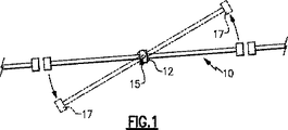
図1および図2を参照すると、ゲートアセンブリ10は、中心軸15の回りを回転するためゲート支持ポスト16によって支持される中央ポスト12を含む。ゲートアセンブリ10の回転により、完成したゲート構造内での空間の開放および閉鎖が容易になる。
With reference to FIGS. 1 and 2, the
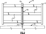
中央ポスト12から外向きに延びるのは、外側ポスト17に取り付けられ、これを支持するレール14である。ゲートアセンブリ10は支持ポスト16の回りを回転可能で、包囲された領域へのアクセスを可能にする。支持ポスト16は、地面32内に固定されたグランドマウント18に取り付けられる。グランドマウント18は、グランドマウント18へ支持ポスト16を固定するための調整ブラケット20を含む。調整ブラケット20はまた支持ポスト16の調整および方向を容易にし、ゲートアセンブリ10を開口内に所望通りに調整する。
Extending outwardly from the
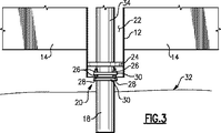
図3を参照すると、グランドマウント18は地面32内に固定され、調整ブラケット20を含む。調整ブラケット20はプレート30を含み、その一方はグランドマウント18に埋め込まれ、他方は内側ポスト34に取り付けられる。この2個のプレート30は、内側ポスト34の方向を調整するため、ひいてはグランドマウント18および周囲のフェンスに対し支持ポスト16を調整するため、ナット26を含むねじ付き部材28によって取り付けられる。
Referring to FIG. 3, the
中央ポスト12は内側ポスト34上に支持され、中心軸15の回りを内側ポスト34に対し回転可能である。下部支持プレート24は中央ポスト12に取り付けられ、内側ポスト34の回りを回転可能である。下部支持プレート24は、摩擦が小さく、内側ポスト16に対して中央ポスト12の容易な回転を可能にする材料から作製される。
The
図4および図5を参照すると、内側ポスト34は、ゲートアセンブリ10の支持と中心軸15周囲の回転とを容易にするジャーナルアセンブリ55を支持する。ジャーナルアセンブリ55は、内側ポスト34に取り付けられた固定プレート36と、中央ポスト12に取り付けられた回転可能プレート38とを含む。中央サポート50は、固定支持プレート36から中心軸15に沿って延びる。1個のボールベアリング54は中央サポート50上に配設される。スリーブ52は回転可能プレート38から、ボールベアリング54と中央サポート50とを覆って延びる。スリーブ52は、ボールベアリング54が中に配設される空洞58を限定する。ゲートアセンブリ10の重量は中心軸15に沿って1個のボールベアリング15上に支持される。スリーブ52は、中央サポート50周囲の回転を容易にする低摩擦材料からなるベアリング面56を含む。
4 and 5, the
回転可能プレート38はポスト12に取り付けられ、内側ポスト34および固定プレート36より大きい。中央ポスト12は回転可能プレート38の外周に取り付けられる。ゲートアセンブリ10と、これによる中央ポスト12の回転は、内側ポスト34に固定された固定プレート36に対して回転可能プレート38を回転させることにより容易になる。例示の内側ポスト34は回転しないが、回転可能支持プレート38は、中央サポート50上に配設されたボールベアリング54上で回転する。例示のゲートアセンブリ10はこれによりボールベアリング50上を中心に位置づけられ、ベアリングはゲートアセンブリ10の重量を支持することになる。
A
スリーブ52と中央サポート50との間の嵌合は、中心軸15周囲でのゲートアセンブリ10の安定した回転を与える運転隙間嵌合である。ベアリング54は、スリーブ52と空洞58との間に所望の嵌合を与える。ベアリング54はまた、内側ポスト34に対するゲートアセンブリ10の回転を提供するのに望ましい低摩擦、高耐久性表面を与える。
The fit between the
例示のジャーナルアセンブリ55は、自動閉鎖バイアス装置も含む。自動閉鎖バイアス装置は、スリーブ52周囲に配設されたバイアス部材44を含む。バイアス部材44は、ゲートアセンブリ10の所望の位置へ戻る選択的回転を容易にする。バイアス部材44は、第1支持プレート36および第2支持プレート38とから延びる対応する脚と係合するアーム46、48を含む。固定プレート36は第1の脚40、回転可能プレート38は第2の脚42を含む。第1支持プレート30に対する回転可能プレート38の回転により、バイアス部材36をポスト40、38の一方と係合せしめる。ゲートアセンブリの解放により、バイアス部材はゲートアセンブリ10を所望の位置に戻す。このようにして、ゲートアセンブリ10は、アクセスを阻止し、出入りを制御するため所望の開口部にゲートを位置づけるための自動帰還機構を備える。
The
支持アセンブリ16は、ゲート構造の中空空洞内に配設される。ゲート構造は、中空部分を含むプラスチックまたはビニール材料から作製されるのが望ましい。本発明では他の材料も利用できる。しかしながら、木や金属等の他の材料は一般に、市販で利用可能なビニールおよびプラスチックフェンスによって与えられる中空空洞を含まない。
ビニールおよびプラスチックフェンスは、簡単に設置できるような方法で設計される。しかしながら、ビニールのフェンスは、片持ち梁式にゲートアセンブリを支持するのに必要な強度を提供しない。従って、ゲートアセンブリの中央部の中空空洞内に配設される支持アセンブリ16は、市販で利用可能なプラスチックまたはビニールのフェンスと共に設置できる、バランスの取れたゲートを提供する。
Vinyl and plastic fences are designed in such a way that they can be easily installed. However, vinyl fences do not provide the strength needed to support the gate assembly in a cantilevered fashion. Accordingly, the
図6を参照すると、例示の動力式ゲートポストアセンブリ60はゲートの自動または遠隔操作ができ、グランドスリーブ68内に受けられ、外側ポスト64を支持する内側ポスト66を含む。グランドスリーブ68は、ゲートポストアセンブリ60の回転位置を調整するための回転調整ブラケット72を含む。ポストアセンブリの回転位置は、回転調整ブラケット72の位置を調整することにより無限に調整可能である。さらに、回転調整ブラケット72を緩めることにより、ポストアセンブリ60がグランドスリーブ68内を自由に回転できるようになり、ゲートの自由な揺動が可能になる。これにより、動力障害の際に作動できる。
With reference to FIG. 6, an exemplary powered
さらに、回転調整ブラケット72は、内向き開放から外向き開放、およびその逆にゲートを変換する。調整ブラケットをゆるめ、ゲートおよびポストアセンブリ60を回転することにより、所望の内向きまたは外向き開放を提供するようゲートの開始位置を再設定する。
Further, the
外側ポスト64は、XおよびY面内でゲートを調整する上部調整ブラケット62を含む。下部調整ブラケット70は、ゲートの取り付けおよびゲートの高さ調整も行う。外側ポスト64はまた、ゲートの様々な取り付け構成を容易にする複数の取り付け孔76を含む。アクセスプレート94は取り外し可能で、ゲートポストアセンブリ60に動力を与えるアクチュエータへのアクセスを提供する。動力リード線74が外側ポスト64内から延びて所望の電力を供給する。
The
図7を参照すると、動力式ポストアセンブリ60は、第1駆動スロット84内に配設された駆動ピン86を駆動するアクチュエータ90を含む。アクチュエータ90は、全体が内側ポスト内に配設されるため視野から隠れる。トラニオン86は、アクチュエータ90を駆動ピン86へリンクする。アクチュエータ90は内側ポスト66に取り付けられ、駆動ピン86は第1駆動スロット84内を移動可能で、外側ポスト64に取り付けられる(図8)。
Referring to FIG. 7, the
例示のアクチュエータ90は、ボールねじ軸65を含むリニアアクチュエータである。ボールねじ軸65は、トラニオン88に取り付けられる。トラニオン88は、回転するポスト部材64の側面の間を延びる。アクチュエータ90の移動が、カムスロット84内で駆動ピン86を線形に動かし、外側ポスト64を対応して回転せしめる。制御装置92をアクチュエータ90と共に内側ポスト66内に含め、アクチュエータ90の無線制御および起動を容易にすることができる。駆動スロット84は、軸15周囲の回転のため、駆動ピン86をねじる方向を含む。
The
内側ポスト66は第1端部80と第2端部78とを含む。第2端部は第2駆動スロット82を含む。第1駆動スロット84は第1方向への外側ポスト64の回転を与え、第2駆動スロット82は第2方向への外側ポスト64の回転を与える。設置中、内側ポスト66は、駆動スロット84、82を所望の回転方向に一致させて設置する。他方の駆動スロット84、82および端部は、グランドスリーブ68内に受けられる。このように、時計回りまたは反時計回り方向へのゲートの回転および開放を可能にするのに、一方の内側ポスト構成しか必要としない。
動力式ポストアセンブリ60は、内側ポスト66の回りを回転する外側ポスト62を含む。例示の外側ポスト部材64は、中空内側空洞を含むプラスチックまたはビニールフェンス構造から作製する。中空内側空洞は、内側ポスト90全体と起動および支持機能を効果的に隠ぺいする。全ての動力式アセンブリ機能は内側ポスト66内で視野から隠される。
The
さらに、作製されたゲート構造を回転するポスト64に取り付けることができる。このように、予め作製されたユニットとして取得した既存の木製またはプラスチックのパネル構造を支持してゲートとして利用することができる。そのため、ポストアセンブリ60は多数の異なる構成および材料のゲート構造に利用することができる。予め作製したゲートパネルの取り付けは、あらゆる周知のファスナを利用して達成することができる。さらに、所望の構成のゲートを支持して用途固有の要件に適合するよう、ポスト60に支持機能を取り付けることができる。
Furthermore, the fabricated gate structure can be attached to a
動力式ポストアセンブリ60全体と、ひいてはゲート全体はグランドスリーブ68から容易に取り外し可能で、ゲート開口部全体の開放を容易にする。さらに、グランドスリーブ68からの容易な取り外しは、回転位置ブラケット72を緩めることによって容易になる。1つの接続による容易な取り外しは、容易な調整、取り外し、再設置を可能にすることにより多くの利点を提供する。
The entire
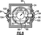
図8を参照すると、駆動ピン86を通る断面図で外側ポスト64への取り付けを示す。外側ポスト64は、アクセスパネル104に覆われた駆動ピン86の端部のための開口を含む。駆動ピン86の端部は、外側ポスト64の各壁を通って延び、ワッシャ98およびクリップ96によって保持される。トラニオン88は、駆動スロット84中に上向きに駆動ピン86を取り付け、駆動する。駆動スロット84のアーチ形状のため、上向きの移動は、外側ポスト64への回転に変換される。
Referring to FIG. 8, the attachment to the
図8を参照しながら図9を参照すると、例示の駆動ピン86は、ベアリング100とスリーブ102とを支持する軸104を含む。ベアリング100は外側ポスト64の壁内に配設され、外側ポスト64の相対回転を容易にする。スリーブ102はトラニオン88と係合し、支持される。
Referring to FIG. 9 with reference to FIG. 8, the
図10を参照すると、上部調整ブラケット62は、ファスナ110により回転可能プレートに取り付けられる第1ブラケット106と第2ブラケット108とを含む。第1および第2ブラケット106および108は、所望の通りにゲートを整列させる相対摺動を提供するスロット112、114を含む。
Referring to FIG. 10, the
図11を参照すると、別の例の動力式ゲートポストアセンブリ120は、固定構造に取り付けるよう構成される。ポストアセンブリ120は、外側ポスト122を支持する内側ポスト124を含む。上部ブラケット126および下部ブラケット128は、ポストまたは他の固定構造への取り付けを提供する。外側ポスト122は、軸15の回りを内側ポスト124に対して回転する。外側ポストは、内側起動機構へのアクセスを提供するアクセスパネル104を含む。ファスナ130を緩め、内側ポスト124を所望の位置へ回転させることにより、回転位置を調整可能である。所望の位置へ来たら、ファスナを締め付けて所望の位置を保持する。外側ポスト122は、あらゆる所望のゲート構成または構造を取り付けるための複数の取り付け孔パターン132を含む。
Referring to FIG. 11, another example powered
図7および図8を参照すると、ポストアセンブリ60の動作は、所望の閉位置で始まる。アクチュエータ90の起動により、トラニオン88が上下する。トラニオン88の上下により、駆動ピン86を駆動スロット84内で移動せしめる。駆動スロット84は、上向きの移動を回転ポスト64の対応する回転移動に変換する所望の形状を含む。プラスチックの中央ポスト64が回転ポストに取り付けられるため、この移動によりゲートアセンブリ10の対応する移動が生じる。
With reference to FIGS. 7 and 8, operation of the
図12を参照すると、別の例の動力式ポスト145は、ピニオン駆動ギア140を含む軸146を駆動する電動モータ134を含む。ピニオン駆動ギア140は、外側リングギア142も含むギアトレイン138の一部である。モータ134はトルクコンバータ136を介して軸146を駆動し、内側ポスト66に対して外側ポスト64を回転させる。ジャーナルアセンブリ52は、支持部材148により内側ポスト66の上に支持される。モータ134の回転により、ギアトレイン148を介して外側ポストを回転せしめる。駆動トレイン内のそれぞれのギアの固有ギア比により、所望のゲート開放速度を与える。
Referring to FIG. 12, another example powered
この例のグランドスリーブ68は、所望の軸位置を与えるため内側ポスト66を受けるロケータプラグ144を含む。内側ポスト66は、回転調整ブラケット72により回転調整可能である。
The
リニアアクチュエータ90およびロータリー電動モータ134を図示するが、ゲートアセンブリの回転を提供可能な他のアクチュエータも本発明の考慮事項内であることが理解される。さらに、パッシブ装置を利用して、所望の位置にゲートを戻し、回転させることができる。パッシブ装置は、例えば空気圧または油圧制動機構としてもよい。
Although
従って、本発明に係るゲートアセンブリは、複雑または重い従来の材料または複雑な強化なしに、プラスチックまたはビニールフェンス等の代替え材料の利用を提供する。ジャーナルアセンブリは低パワーモータの利用を提供し、これにより内側ポスト内への駆動システムの完全な設置を可能にする。さらに、例示の動力式ポストはヒンジおよびゲートサポートとアクチュエータの両方であるため、さらなるヒンジや取り付け装置を必要としない。さらに、本発明に係るゲートアセンブリは、プラスチックまたはビニールのゲート材料または取り付け具内に支持アセンブリを隠し、プラスチックまたはビニールフェンスによる所望の均一な外観を維持する。 Thus, the gate assembly according to the present invention provides the use of alternative materials such as plastic or vinyl fences without complex or heavy conventional materials or complex reinforcement. The journal assembly provides the use of a low power motor, thereby allowing a complete installation of the drive system within the inner post. Further, the exemplary powered post is both a hinge and gate support and an actuator, so no additional hinges or attachment devices are required. Furthermore, the gate assembly according to the present invention conceals the support assembly within a plastic or vinyl gate material or fixture and maintains the desired uniform appearance with the plastic or vinyl fence.
本発明の好適な実施例を開示したが、当業の通常の技術を有する作業者は、本発明の範囲内で一定の修正が行われることを理解するであろう。それ故、以下の特許請求の範囲は、本発明の真の範囲および内容を決定するものために検討しなければならない。 While a preferred embodiment of the present invention has been disclosed, those having ordinary skill in the art will understand that certain modifications may be made within the scope of the present invention. Therefore, the following claims should be studied to determine the true scope and content of this invention.
Claims (13)
内側ポストの周りを回転可能な外側ポストと、
内側ポストと外側ポストとの間に支持され、外側ポストの回転軸に沿って中心に位置する単一のボールベアリングを含むジャーナル軸受部で、ボールベアリングは内側ポスト上に外側ポストを支持するものと、
内側ポストに対して外側ポストを選択的に回転させるため内側ポストに取り付けられたアクチュエータであって、アクチュエータは線形的に可動な部分を有するものと、
線形的に可動な部分と共に線形的に移動可能であり、線形的に可動な部分の周りを回転可能である、線形的に可動な部分上に支持されたトラニオンと、
トラニオンによって支持された駆動ピンであって、内側ポストのアーチ形状の駆動スロット内での駆動ピンの動きに応じてトラニオンが線形的に可動な部分の周りを回転して外側ポストの回転運動を提供するように、外側ポスト中まで内側ポストのアーチ形状の駆動スロットを通して延びているものと、
を含む動力式ゲートポストシステム。An inner post including first and second ends and an inner space, the inner post having at least one arcuate drive slot;
An outer post rotatable around the inner post,
A journal bearing that includes a single ball bearing supported between the inner and outer posts and centered along the axis of rotation of the outer post, the ball bearing supporting the outer post on the inner post; ,
An actuator attached to the inner post for selectively rotating the outer post relative to the inner post, the actuator having a linearly movable portion;
A trunnion supported on the linearly movable part, linearly movable with the linearly movable part, and rotatable about the linearly movable part;
A drive pin supported by trunnion, the rotational movement of the outer post trunnion rotates around the linearly movable part in response to movement of the drive pin in the drive slot of the arch shape of the inner side posts so as to provide, to that extends through the drive slots of the arch shape of the inner side post until in the outer post,
Powered gate post system including.
内側ポスト上での回転軸周囲の移動のため支持される外側ポストで、ゲートは外側ポストに取り付けられるものと、
外側ポストと、外側ポストに取り付けられたゲートとを支持するためのジャーナル軸受部で、ジャーナル軸受部は回転軸に沿って中心に位置付けられた単一のボールベアリングを含むものと、
内側ポストに取り付けられ、線形的に可動な部分を有するアクチュエータと、
線形的に可動な部分上に支持された駆動ピンであって、線形的に可動な部分の線形運動が内側ポストのアーチ形状の駆動スロット内において回転軸の周りで駆動ピンを回転させて外側ポストの回転運動を提供するように、外側ポスト中まで内側ポストのアーチ形状の駆動スロットを通して延びているものと、
を含むゲートの支持と開放のための動力式ポスト。An inner post fixed to the movement of the gate, the inner post having at least one arcuate drive slot;
An outer post supported for movement around the axis of rotation on the inner post, with the gate attached to the outer post;
An outer post, in the journal bearing part for supporting a gate attached to the outer side post, as the journal bearing portion comprising a single ball bearing positioned at the center along the axis of rotation,
An actuator attached to the inner post and having a linearly movable part;
Linearly a supported drive pin on the movable part, and linearly rotates the drive pin about the axis of rotation in a movable portion of the linear motion drive slot of the arch shape of the inner side posts outside to provide rotational movement of the post, and which extends through the drive slots of the arch shape of the inner side post until in the outer post,
Powered post for gate support and opening including.
Applications Claiming Priority (5)
| Application Number | Priority Date | Filing Date | Title |
|---|---|---|---|
| US78623106P | 2006-03-27 | 2006-03-27 | |
| US60/786,231 | 2006-03-27 | ||
| US83190006P | 2006-07-19 | 2006-07-19 | |
| US60/831,900 | 2006-07-19 | ||
| PCT/US2007/065016 WO2007112388A2 (en) | 2006-03-27 | 2007-03-27 | Gate support device |
Publications (2)
| Publication Number | Publication Date |
|---|---|
| JP2009531575A JP2009531575A (en) | 2009-09-03 |
| JP5124559B2 true JP5124559B2 (en) | 2013-01-23 |
Family
ID=38485262
Family Applications (1)
| Application Number | Title | Priority Date | Filing Date |
|---|---|---|---|
| JP2009503213A Expired - Fee Related JP5124559B2 (en) | 2006-03-27 | 2007-03-27 | Gate support device |
Country Status (9)
| Country | Link |
|---|---|
| US (2) | US7958675B2 (en) |
| EP (1) | EP1999335B1 (en) |
| JP (1) | JP5124559B2 (en) |
| CN (1) | CN101449019B (en) |
| AU (1) | AU2007230606B2 (en) |
| CA (1) | CA2647091C (en) |
| ES (1) | ES2390832T3 (en) |
| MX (1) | MX2008012390A (en) |
| WO (1) | WO2007112388A2 (en) |
Families Citing this family (23)
| Publication number | Priority date | Publication date | Assignee | Title |
|---|---|---|---|---|
| CA2647091C (en) * | 2006-03-27 | 2011-06-21 | Edward J. Stull | Gate support device |
| US8296998B2 (en) * | 2006-03-27 | 2012-10-30 | Turnstyle Intellectual Property, Llc | Powered actuator |
| BE1017519A6 (en) * | 2007-03-22 | 2008-11-04 | Meersman Bvba | AUTOMATIC HINGE FOR DOORS, GATES, GATES E.D. |
| US20080307709A1 (en) * | 2007-06-15 | 2008-12-18 | Stull Edward J | Dual swing powered gate actuator |
| US20100319262A1 (en) * | 2008-01-30 | 2010-12-23 | Stull Edward J | Powered gate |
| WO2010011810A2 (en) * | 2008-07-23 | 2010-01-28 | Turnstyle Intellectual Property, Llc | Enclosed powered gate post |
| US8413297B2 (en) * | 2008-12-10 | 2013-04-09 | The Chamberlain Group, Inc. | Apparatus and method pertaining to a pivoting barrier |
| US8584401B2 (en) * | 2008-12-10 | 2013-11-19 | The Chamberlain Group, Inc. | Apparatus and method pertaining to a pre-configured post for use with an automatically-movable barrier |
| US9677317B2 (en) | 2009-03-03 | 2017-06-13 | The Chamberlain Group, Inc. | Variable speed movable barrier operator |
| WO2010118277A2 (en) * | 2009-04-10 | 2010-10-14 | Turnstyle Intellectual Property, Llc | Powered gate post with slots for positional adjustment |
| MX344642B (en) | 2009-12-29 | 2017-01-04 | W R Grace & Co -Conn * | Compositions for forming films having a desired degree of obscuration and methods of making and using the same. |
| US20130042531A1 (en) * | 2011-02-10 | 2013-02-21 | Advantage Gate Products Inc. | Gate operator, method for manufacturing same and folded gate assembly utilizing same |
| USD741688S1 (en) * | 2013-01-23 | 2015-10-27 | Water Renu Llc | Bracket with slotted side walls |
| US9051117B2 (en) * | 2013-03-14 | 2015-06-09 | David Alan Kirchhoff | Actuator for opening and closing lid for bulk storage bin |
| US9145724B2 (en) * | 2014-03-30 | 2015-09-29 | David Edmond Dudley | Floor-mounting gate-closer post with rotary dampener |
| CN105178789B (en) * | 2015-08-16 | 2017-03-01 | 李洪硕 | A kind of heavy type iron gate installation auxiliary device |
| CN105781232B (en) * | 2016-05-09 | 2018-03-09 | 常州市第一人民医院 | Dept. of radiology is special to forbid railing |
| CN108005537B (en) * | 2017-12-19 | 2019-06-28 | 合肥草木蕃景生态科技有限公司 | A kind of overturning wall door |
| US10626661B2 (en) * | 2018-03-22 | 2020-04-21 | Peter Miller | Large bollard molded post doors |
| US11091941B2 (en) * | 2018-03-22 | 2021-08-17 | Peter Miller | Large bollard post doors |
| KR102192430B1 (en) * | 2019-07-09 | 2020-12-17 | 김민재 | A fence that can be opened and closed by rotation |
| CN110778238A (en) * | 2019-09-25 | 2020-02-11 | 奇点物联网股份有限公司 | Be used for construction maintenance to decorate door shield |
| US20220356659A1 (en) * | 2021-05-04 | 2022-11-10 | Garcia C. David | Pneumatic Fare Gare |
Family Cites Families (93)
| Publication number | Priority date | Publication date | Assignee | Title |
|---|---|---|---|---|
| US398718A (en) * | 1889-02-26 | George ford | ||
| US28205A (en) | 1860-05-08 | Samuel h | ||
| US82648A (en) * | 1868-09-29 | smith | ||
| US163084A (en) | 1875-05-11 | Improvement in automatic gates | ||
| US571237A (en) | 1896-11-10 | philpott | ||
| US447819A (en) | 1891-03-10 | Swinging gate | ||
| US203575A (en) | 1878-05-14 | Improvement in gates | ||
| US326548A (en) | 1885-09-22 | Gate-hanger | ||
| US363964A (en) | 1887-05-31 | philpott | ||
| US780623A (en) | 1904-11-08 | 1905-01-24 | Thomas C Sisk | Farm-gate. |
| US911694A (en) | 1908-03-16 | 1909-02-09 | Milwaukee Hardware Mfg Company | Hinge. |
| US920305A (en) | 1908-06-08 | 1909-05-04 | James Finch | Gate. |
| US933677A (en) | 1908-09-25 | 1909-09-07 | John E Smith | Gate. |
| US1126067A (en) | 1914-07-16 | 1915-01-26 | Willis C Nolte | Gate-hinge. |
| US1221796A (en) | 1915-08-11 | 1917-04-03 | William E Egbert | Kitchen-cabinet. |
| US1383961A (en) | 1918-09-07 | 1921-07-05 | Melugin Frank | Gate-hinge |
| US1462766A (en) * | 1921-01-24 | 1923-07-24 | John E Post | Gate |
| US1494911A (en) | 1922-11-16 | 1924-05-20 | Heselschwerdt Samuel | Gate |
| US1540490A (en) | 1924-02-07 | 1925-06-02 | Summit Brass & Bronze Works In | Gate mounting |
| US1594260A (en) * | 1925-05-18 | 1926-07-27 | Charles J Herr | Gate |
| US1630200A (en) * | 1925-09-04 | 1927-05-24 | Ayres P Merrill | Gate |
| US1891739A (en) | 1931-12-18 | 1932-12-20 | Wenger Samuel | Automatic railroad crossing signal |
| US2050584A (en) | 1932-02-10 | 1936-08-11 | Gen Bronze Corp | Revolving door |
| US1947733A (en) | 1932-09-17 | 1934-02-20 | Gen Bronze Corp | Governor for revolving doors |
| US2111773A (en) | 1936-12-11 | 1938-03-22 | Internat Door Company | Lower journal for revolving doors |
| US2151052A (en) * | 1937-12-29 | 1939-03-21 | Lon R Smart | Self-closing gate |
| US2181464A (en) | 1938-03-31 | 1939-11-28 | Renner Ernest | Swinging gate or the like |
| US2251482A (en) * | 1940-05-21 | 1941-08-05 | Stanley Works | Hinge |
| GB585176A (en) * | 1944-08-15 | 1947-01-31 | James George Munro | Improvements in or relating to gates |
| US2564485A (en) | 1947-07-24 | 1951-08-14 | Renna | Revolving door and cabinet |
| US2686941A (en) * | 1950-10-04 | 1954-08-24 | Walter E Patten | Refrigerated warehouse door and hinge construction |
| US2924843A (en) * | 1958-02-14 | 1960-02-16 | Julius W Tykeson | Spring door hinges |
| FR1348159A (en) | 1963-02-15 | 1964-01-04 | Batic Sa | Device for activating the control members of the speed changes of automated machines |
| US3315413A (en) * | 1965-02-08 | 1967-04-25 | American Sterilizer Co | Power operated door |
| US3364620A (en) | 1965-07-29 | 1968-01-23 | Gen Bronze Corp | Revolving doors |
| US3626547A (en) | 1969-10-02 | 1971-12-14 | Auto Comp Devices Inc | Door hinge |
| US3717954A (en) | 1971-10-20 | 1973-02-27 | A Sheckells | Motor driven operating mechanism for revolving doors |
| CA1043966A (en) | 1975-12-01 | 1978-12-12 | Rudolph E. Parisien | Gate and spring hinge therefore |
| US4124955A (en) | 1977-05-13 | 1978-11-14 | Eckel Industries, Inc. | Automatic closure |
| US4174621A (en) | 1977-10-12 | 1979-11-20 | Umc Industries, Inc. | Torque limiting overload coupling |
| US4231190A (en) | 1978-10-04 | 1980-11-04 | My-D-Han-D Manufacturing Co. | Remotely controlled gate opener |
| US4295297A (en) | 1978-10-06 | 1981-10-20 | Noel Carroll | Revolving security door |
| DE3261555D1 (en) | 1981-09-25 | 1985-01-24 | Wanzl Kg Rudolf | Pivoting gate equipment for passageways |
| GB8326917D0 (en) | 1983-10-07 | 1983-11-09 | Telektron Ltd | Valve actuator |
| JPS60227012A (en) | 1984-01-27 | 1985-11-12 | ハンス ゲオルグ ハンネマン | Bearing assembly |
| US4572595A (en) * | 1984-04-13 | 1986-02-25 | Craig Chapman C | Rotational shelf apparatus |
| AT382200B (en) | 1985-04-16 | 1987-01-26 | Ife Gmbh | ROTARY DRIVE, IN PARTICULAR FOR VEHICLE DOORS |
| DE3513666A1 (en) | 1985-04-16 | 1986-10-30 | Efaflex Transport- und Lager-Technik GmbH, 8301 Bruckberg | Industrial door |
| US5035082A (en) | 1985-07-02 | 1991-07-30 | Embassy Gates Associates, L.P. | Gate support and operating mechanism |
| US4658543A (en) | 1985-07-03 | 1987-04-21 | Carr Frederick J | Swinging lift gate |
| DE3532514C1 (en) | 1985-09-12 | 1987-04-23 | Bode & Co Geb | Drive device for a rotating column, in particular for moving pivoting door leaves on motor vehicles |
| US4649597A (en) | 1986-01-10 | 1987-03-17 | Cacicedo Paulino A | Automatic gate closure apparatus |
| US4665650A (en) * | 1986-05-12 | 1987-05-19 | Hall Richard C | Control gate assembly |
| US5050344A (en) | 1989-03-30 | 1991-09-24 | Skeem Wayne B | Gate opening device |
| DE8904747U1 (en) | 1989-04-15 | 1989-06-01 | Wexler, Zeev, Hod Hacarmel, Haifa, Il | |
| JPH0314273A (en) | 1989-06-13 | 1991-01-22 | Toyota Autom Loom Works Ltd | Electrostatic induction transistor |
| JPH0617964Y2 (en) * | 1989-06-23 | 1994-05-11 | 株式会社丸八産業 | Rotating window bearing device |
| US4989368A (en) | 1989-08-22 | 1991-02-05 | Trikilis Emmanuel M | Turnstile assembly |
| DE3928749A1 (en) | 1989-08-31 | 1991-03-07 | Micronel Ag | AXIAL LOCKING OF THE SHAFT OF A SMALL ENGINE |
| US5036620A (en) * | 1990-09-17 | 1991-08-06 | Bc Research & Development, Inc. | Safety enhanced pivoting door operator |
| US5138796A (en) * | 1990-10-29 | 1992-08-18 | Grainger Dennis M | Self-closing gate |
| US5192054A (en) * | 1991-01-24 | 1993-03-09 | Ivan Sharp | Prefabricated simulated wrought iron and like fencing systems and methods |
| US5133152A (en) | 1991-12-26 | 1992-07-28 | Grancagnolo Edward J | Heavy duty constant use self closing gate |
| US5215290A (en) * | 1992-05-19 | 1993-06-01 | Khalessi Hamid R | Plastic fence |
| US5277488A (en) | 1992-05-22 | 1994-01-11 | Liam Cleary | Refrigerator with rotatable shelves |
| US5373664A (en) | 1992-12-09 | 1994-12-20 | Butler; Colin | Self-contained automatic gate system |
| JPH076499A (en) | 1993-06-14 | 1995-01-10 | Sony Corp | Spindle servo device |
| JP2590110Y2 (en) * | 1993-06-30 | 1999-02-10 | 株式会社西製作所 | Gate mounting hinges |
| US5564367A (en) * | 1994-03-28 | 1996-10-15 | R. W. Industries, Inc. | Compact fenced enclosure |
| CN1118401A (en) * | 1994-09-06 | 1996-03-13 | 吴水森 | Multifunctional rotary inductive automatic door |
| IT1279208B1 (en) * | 1995-05-16 | 1997-12-04 | Bitron Spa | COUPLING SYSTEM WITH MINIMUM AND CONTROLLED AXIAL CLEARANCE BETWEEN A SHAFT AND A SUPPORT IN RELATIVE ROTATION, AND RELATED PROCEDURES |
| JP3038150B2 (en) * | 1995-07-04 | 2000-05-08 | 株式会社ヒガノ | Gate door |
| US5904115A (en) | 1996-10-18 | 1999-05-18 | Lincoln Industries Division Of Progress Rail Services | Clearance pole assembly |
| JPH10169342A (en) | 1996-12-09 | 1998-06-23 | Tateyama Alum Gaisou Kk | Open-close device in revolving type gate door |
| JPH1162444A (en) | 1997-08-26 | 1999-03-05 | Matsushita Electric Works Ltd | Gate door device |
| JPH11131954A (en) | 1997-10-28 | 1999-05-18 | Matsushita Electric Works Ltd | Gate |
| JP3278642B2 (en) * | 1998-12-01 | 2002-04-30 | 株式会社東京精密 | Safety doors and devices for manufacturing or inspecting semiconductors with safety doors |
| US6119399A (en) | 1999-02-09 | 2000-09-19 | Mccain; Roy L. | Channel guided parallelogram gate |
| EP1143096A1 (en) | 2000-04-07 | 2001-10-10 | SITES S.r.l. | Rotating drive apparatus |
| JP2001295233A (en) * | 2000-04-14 | 2001-10-26 | Kanto Regional Development Bureau Ministry Of Land Infrastructure & Transport | Vehicle entry gate |
| GB2366324A (en) | 2000-08-30 | 2002-03-06 | Stanley Edward Snelgrove | Self-closing gates with rotatable sleeve |
| DE20121216U1 (en) * | 2001-06-15 | 2002-06-06 | Wanzl Metallwarenfabrik Kg | Swing door to close a passage |
| JP4155751B2 (en) | 2002-03-20 | 2008-09-24 | 日立工機株式会社 | Electric tool |
| US6990772B2 (en) * | 2003-06-05 | 2006-01-31 | Alan Eckel | Automatic door closure for double-acting doors |
| US7429032B2 (en) | 2004-01-16 | 2008-09-30 | Turnstyle Intellectual Property, Llc | Balanced gate mechanism |
| US7367891B2 (en) | 2004-11-23 | 2008-05-06 | Hr Textron, Inc. | Techniques for controlling transfer of torque using detent members responsive to radial force |
| KR100641269B1 (en) | 2005-07-29 | 2006-11-03 | 왕복권 | Power transmiting system for rotary wings of automatic revolving door |
| CA2647091C (en) | 2006-03-27 | 2011-06-21 | Edward J. Stull | Gate support device |
| WO2007118184A2 (en) * | 2006-04-07 | 2007-10-18 | Stull Edward J | Temporary gate assembly |
| US20080237561A1 (en) | 2006-10-25 | 2008-10-02 | 440 Fence Company, Inc. | Hingeless fence |
| US20080244978A1 (en) | 2007-04-05 | 2008-10-09 | Rahmi Soyugenc | Motorized security revolving door |
| US8136297B2 (en) | 2007-09-28 | 2012-03-20 | Babcock & Wilcox Technical Services Y-12, Llc | Speed control system for an access gate |
| US20100319262A1 (en) | 2008-01-30 | 2010-12-23 | Stull Edward J | Powered gate |
-
2007
- 2007-03-27 CA CA2647091A patent/CA2647091C/en not_active Expired - Fee Related
- 2007-03-27 US US11/691,647 patent/US7958675B2/en not_active Expired - Fee Related
- 2007-03-27 MX MX2008012390A patent/MX2008012390A/en active IP Right Grant
- 2007-03-27 ES ES07759462T patent/ES2390832T3/en active Active
- 2007-03-27 EP EP07759462A patent/EP1999335B1/en not_active Not-in-force
- 2007-03-27 AU AU2007230606A patent/AU2007230606B2/en not_active Ceased
- 2007-03-27 WO PCT/US2007/065016 patent/WO2007112388A2/en active Application Filing
- 2007-03-27 CN CN2007800112113A patent/CN101449019B/en not_active Expired - Fee Related
- 2007-03-27 JP JP2009503213A patent/JP5124559B2/en not_active Expired - Fee Related
-
2011
- 2011-05-17 US US13/109,114 patent/US8291643B2/en not_active Expired - Fee Related
Also Published As
| Publication number | Publication date |
|---|---|
| ES2390832T3 (en) | 2012-11-16 |
| WO2007112388A2 (en) | 2007-10-04 |
| EP1999335B1 (en) | 2012-07-25 |
| WO2007112388A3 (en) | 2007-11-22 |
| CA2647091A1 (en) | 2007-10-04 |
| CN101449019B (en) | 2012-11-21 |
| US8291643B2 (en) | 2012-10-23 |
| CA2647091C (en) | 2011-06-21 |
| US20070221904A1 (en) | 2007-09-27 |
| MX2008012390A (en) | 2009-01-15 |
| AU2007230606B2 (en) | 2011-09-01 |
| CN101449019A (en) | 2009-06-03 |
| AU2007230606A1 (en) | 2007-10-04 |
| EP1999335A2 (en) | 2008-12-10 |
| JP2009531575A (en) | 2009-09-03 |
| US7958675B2 (en) | 2011-06-14 |
| US20110214353A1 (en) | 2011-09-08 |
Similar Documents
| Publication | Publication Date | Title |
|---|---|---|
| JP5124559B2 (en) | Gate support device | |
| US7484333B2 (en) | Method of using a door operator | |
| EP0648307B1 (en) | Compact counterbalancing system for sectional doors | |
| US6089304A (en) | Compact track system with rear mount counterbalance system for sectional doors | |
| WO2005073494A1 (en) | Balanced gate mechanism | |
| KR100789666B1 (en) | Link device capable for controlling height for use in refrigerator doors | |
| EP3216961B1 (en) | Modular and multi-purpose platform for moving doors and sliding doors | |
| US8296998B2 (en) | Powered actuator | |
| KR101066049B1 (en) | Door stopper apparatus having actuator structure | |
| KR100785761B1 (en) | Traffic gate for parking lot | |
| EP3679215B1 (en) | Gate closer suited to be retrofitted onto a gate with an eyebolt hinge | |
| WO1996036784A1 (en) | Rear mount counterbalance system for sectional doors | |
| JPH10169342A (en) | Open-close device in revolving type gate door | |
| JP4496038B2 (en) | Slewing gate | |
| JPH0520875Y2 (en) | ||
| JP5630878B2 (en) | Large weight gate opening and closing device | |
| CA2241959C (en) | Compact track system with rear mount counterbalance system for sectional doors | |
| JPH10102959A (en) | Rotary gate | |
| EP1255015A2 (en) | Door closure mechanism | |
| JP2022020354A (en) | Door drive device and door system | |
| GB2431200A (en) | Self-closing gate with rotatable sleeve |
Legal Events
| Date | Code | Title | Description |
|---|---|---|---|
| A131 | Notification of reasons for refusal |
Free format text: JAPANESE INTERMEDIATE CODE: A131 Effective date: 20110614 |
|
| A521 | Written amendment |
Free format text: JAPANESE INTERMEDIATE CODE: A523 Effective date: 20110909 |
|
| A131 | Notification of reasons for refusal |
Free format text: JAPANESE INTERMEDIATE CODE: A131 Effective date: 20111213 |
|
| A601 | Written request for extension of time |
Free format text: JAPANESE INTERMEDIATE CODE: A601 Effective date: 20120312 |
|
| A602 | Written permission of extension of time |
Free format text: JAPANESE INTERMEDIATE CODE: A602 Effective date: 20120319 |
|
| A521 | Written amendment |
Free format text: JAPANESE INTERMEDIATE CODE: A523 Effective date: 20120611 |
|
| TRDD | Decision of grant or rejection written | ||
| A01 | Written decision to grant a patent or to grant a registration (utility model) |
Free format text: JAPANESE INTERMEDIATE CODE: A01 Effective date: 20121002 |
|
| A01 | Written decision to grant a patent or to grant a registration (utility model) |
Free format text: JAPANESE INTERMEDIATE CODE: A01 |
|
| A61 | First payment of annual fees (during grant procedure) |
Free format text: JAPANESE INTERMEDIATE CODE: A61 Effective date: 20121029 |
|
| FPAY | Renewal fee payment (event date is renewal date of database) |
Free format text: PAYMENT UNTIL: 20151102 Year of fee payment: 3 |
|
| R150 | Certificate of patent or registration of utility model |
Free format text: JAPANESE INTERMEDIATE CODE: R150 |
|
| LAPS | Cancellation because of no payment of annual fees |