EP0245982A2 - Direktgeheizte Kathode - Google Patents
Direktgeheizte Kathode Download PDFInfo
- Publication number
- EP0245982A2 EP0245982A2 EP87303668A EP87303668A EP0245982A2 EP 0245982 A2 EP0245982 A2 EP 0245982A2 EP 87303668 A EP87303668 A EP 87303668A EP 87303668 A EP87303668 A EP 87303668A EP 0245982 A2 EP0245982 A2 EP 0245982A2
- Authority
- EP
- European Patent Office
- Prior art keywords
- substrate
- cathode
- wire
- tube
- powdered metal
- Prior art date
- Legal status (The legal status is an assumption and is not a legal conclusion. Google has not performed a legal analysis and makes no representation as to the accuracy of the status listed.)
- Withdrawn
Links
- 239000012255 powdered metal Substances 0.000 claims abstract description 15
- 239000002184 metal Substances 0.000 claims abstract description 6
- 239000011810 insulating material Substances 0.000 claims abstract description 3
- 239000000758 substrate Substances 0.000 claims description 25
- 238000005245 sintering Methods 0.000 claims description 6
- 238000010438 heat treatment Methods 0.000 claims description 4
- 239000000463 material Substances 0.000 claims description 4
- 230000037431 insertion Effects 0.000 claims 1
- 238000003780 insertion Methods 0.000 claims 1
- PNEYBMLMFCGWSK-UHFFFAOYSA-N aluminium oxide Inorganic materials [O-2].[O-2].[O-2].[Al+3].[Al+3] PNEYBMLMFCGWSK-UHFFFAOYSA-N 0.000 abstract description 3
- 239000000843 powder Substances 0.000 abstract 1
- 239000000919 ceramic Substances 0.000 description 5
- 239000012212 insulator Substances 0.000 description 3
- 238000010276 construction Methods 0.000 description 2
- 238000005507 spraying Methods 0.000 description 1
Images
Classifications
-
- H—ELECTRICITY
- H01—ELECTRIC ELEMENTS
- H01J—ELECTRIC DISCHARGE TUBES OR DISCHARGE LAMPS
- H01J23/00—Details of transit-time tubes of the types covered by group H01J25/00
- H01J23/02—Electrodes; Magnetic control means; Screens
- H01J23/04—Cathodes
- H01J23/05—Cathodes having a cylindrical emissive surface, e.g. cathodes for magnetrons
Definitions
- This invention relates to directly heated cathodes and in particular, though not exclusively, to directly heated cathodes for use in magnetron and like electronic devices.
- One object of the present invention is to provide improved directly heated cathodes, and electronic devices utilising the same, of relatively rugged construction.
- a directly heated cathode comprises, sintered together, an elongate powdered metal substrate or mush having embedded therein and co-extensive therewith for at least a substantial part of the length thereof, a wire which is coated with an insulating material whereby said wire is electrically isolated from said substrate, electrical connections for said cathode to said substrate and to said wire being at the same end of said elongate sintered assembly and the path for heater current comprising the substrate and the wire.
- the wire acts as a return path for the heater current.
- said substrate is tubular and said tubular substrate and said wire are coaxial.
- said substrate is partially encased in an outer metal tube, said outer tube, the powdered metal of said substrate and said wire being sintered together.
- an electrical connection for said substrate is made at one end of said tube, said wire emerging from the substrate at the same end of said tube.
- said wire and, where the same is provided, said outer tube are of a material having a co-efficient of thermal expansion similar to that of the powdered metal of said substrate, after sintering.
- the thickness of said wire is chosen such that its electrical heating effect per unit length is similar or equivalent to that of the powdered metal of said substrate, after sintering.
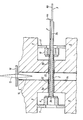
- the cathode itself consists of a cylindrical metal tube 1 within which is a filling 2 of powdered metal through the middle of which passes a return heater wire 3, which is not shown in section for the sake of clarity.
- the powdered metal filling 2 extends beyond one end of the tube 1, so that part of the filling 2 shown to the right as viewed is contained within the tube 1 and that to the left is outside it.
- the return heater wire 3 is coated with alumina 3a (e.g. by spraying) where it would otherwise be in contact with the powdered metal filling 2, so as electrically to insulate the one from the other.
- the end 3b of the wire 3 other than that to which external connection is made is bare of alumina, to provide electrical contact between the wire 3 and the filling 2 at the left-hand end of the cathode as shown.
- the tube 1, coated heater wire 3 and powdered metal filling 2 are sintered together.
- the substrate formed by the sintered powdered metal is impregnated with emissive material and electrical connections 4a and 4b for directly heating the cathode thus formed are provided at the same end of the cathode tube 1 and the return heater wire 3 respectively.
- the materials of the tube 1 and the return wire 3 are chosen to have a coefficient of thermal expansion similar to that of the powdered metal filling 2, after sintering, and the thickness of the return wire 3 is chosen such that its electrical heating effect per unit length is equivalent to that of said filling 2, after sintering.
- End hat tube 5a is carried by a ceramic insulator 6 which is attached to a support washer 7 mounted upon one (referenced 8) of the pole pieces of the magnetron.
- End hat tube 5b is similarly carried by a ceramic insulator 10 mounted on a support washer 11 which is mounted upon the other pole piece (referenced 9) of the magnetron.
- the cathode support tubes 5a and 5b are referred to as "end hat” tubes because both are flared at their innermost ends 12, 13 respectively so as to duplicate the function of conventional "end hats” and act to constrain the generated space charge.
- the "end hat” tubes 5a and 5b are assembled so as to be carried separately by their respective ceramic insulators 6,10, support washers 7,8 and pole pieces 8,9 with concentricity achieved by jigging.
- the "end hat” tubes 5a, 5b mounted within the pole pieces 8,9 and assembled with the magnetron anode 14 are then ready to accept the completely processed cathode with its cathode tube 1, from one end (the right-hand end as viewed).
- the output waveguide from the anode 14 of the magnetron is closed by a high frequency window consisting of a ceramic rod 15 passing through a closure wall 16.
- Ceramic rod 15 is formed with a conical taper on either side of the closure wall 16.
Landscapes
- Microwave Tubes (AREA)
- Solid Thermionic Cathode (AREA)
Applications Claiming Priority (2)
| Application Number | Priority Date | Filing Date | Title |
|---|---|---|---|
| GB868611967A GB8611967D0 (en) | 1986-05-16 | 1986-05-16 | Directly heated cathodes |
| GB8611967 | 1986-05-16 |
Publications (2)
| Publication Number | Publication Date |
|---|---|
| EP0245982A2 true EP0245982A2 (de) | 1987-11-19 |
| EP0245982A3 EP0245982A3 (de) | 1989-06-14 |
Family
ID=10597971
Family Applications (1)
| Application Number | Title | Priority Date | Filing Date |
|---|---|---|---|
| EP87303668A Withdrawn EP0245982A3 (de) | 1986-05-16 | 1987-04-27 | Direktgeheizte Kathode |
Country Status (4)
| Country | Link |
|---|---|
| US (1) | US4810925A (de) |
| EP (1) | EP0245982A3 (de) |
| JP (1) | JPS63932A (de) |
| GB (2) | GB8611967D0 (de) |
Families Citing this family (1)
| Publication number | Priority date | Publication date | Assignee | Title |
|---|---|---|---|---|
| US7791047B2 (en) * | 2003-12-12 | 2010-09-07 | Semequip, Inc. | Method and apparatus for extracting ions from an ion source for use in ion implantation |
Family Cites Families (26)
| Publication number | Priority date | Publication date | Assignee | Title |
|---|---|---|---|---|
| US633350A (en) * | 1896-07-23 | 1899-09-19 | Orlando M Thowless | Burner for incandescent lamps. |
| US792001A (en) * | 1903-07-25 | 1905-06-13 | Gen Electric | Film-coated wire. |
| US1701356A (en) * | 1923-06-09 | 1929-02-05 | Gen Electric | Electrical discharge device |
| US1881644A (en) * | 1929-02-28 | 1932-10-11 | Lester L Jones | Electron discharge cathode |
| FR718616A (fr) * | 1930-11-26 | 1932-01-27 | Aeg | Cathode à chauffage indirect et son procédé de fabrication |
| US2092815A (en) * | 1935-11-23 | 1937-09-14 | Rca Corp | Cathode heater insulation |
| US2172207A (en) * | 1936-09-19 | 1939-09-05 | Siemens Ag | Glow cathode |
| US2463398A (en) * | 1945-07-09 | 1949-03-01 | Kusch Polykarp | Cathode structure for magnetrons |
| NL69250C (de) * | 1946-03-05 | |||
| US2473550A (en) * | 1947-08-19 | 1949-06-21 | Raytheon Mfg Co | Directly heated cathode |
| US2675498A (en) * | 1948-12-07 | 1954-04-13 | Raytheon Mfg Co | Cathode for electron discharge devices |
| US2647216A (en) * | 1950-04-01 | 1953-07-28 | Rca Corp | Dispenser cathode |
| US2675948A (en) * | 1950-09-01 | 1954-04-20 | Sterling D Mallory | Coat and pants hanger attachment for use on suit hangers |
| US2682511A (en) * | 1950-12-16 | 1954-06-29 | Raytheon Mfg Co | Thermionic cathodes |
| US3221203A (en) * | 1962-06-01 | 1965-11-30 | Rca Corp | Sintered metal conductor support |
| US3297901A (en) * | 1964-06-05 | 1967-01-10 | Litton Industries Inc | Dispenser cathode for use in high power magnetron devices |
| GB1129615A (en) * | 1965-03-11 | 1968-10-09 | English Electric Valve Co Ltd | Improvements in or relating to electron discharge device cathodes |
| NL7109224A (de) * | 1971-07-03 | 1973-01-05 | ||
| US3766423A (en) * | 1971-12-03 | 1973-10-16 | Itt | Integral emissive electrode |
| US3852105A (en) * | 1972-04-07 | 1974-12-03 | Rca Corp | Fabrication of dark heaters |
| US3808043A (en) * | 1972-05-30 | 1974-04-30 | Rca Corp | Method of fabricating a dark heater |
| NL167796C (nl) * | 1972-05-30 | 1982-01-18 | Philips Nv | Werkwijze voor het vervaardigen van een met lanthaanhexaboride geactiveerde kathode voor een elektrische ontladingsbuis. |
| DE2732960C2 (de) * | 1977-07-21 | 1982-04-01 | Philips Patentverwaltung Gmbh, 2000 Hamburg | Glühkathode und Verfahren zu ihrer Herstellung |
| DE3014216A1 (de) * | 1980-04-14 | 1981-10-15 | Philips Patentverwaltung Gmbh, 2000 Hamburg | Gluehkathode fuer eine elektronenroehre |
| GB2102196A (en) * | 1981-05-30 | 1983-01-26 | English Electric Valve Co Ltd | Multicavity magnetron anode structure |
| US4634921A (en) * | 1984-07-03 | 1987-01-06 | Sony Corporation | Thermionic cathode heater |
-
1986
- 1986-05-16 GB GB868611967A patent/GB8611967D0/en active Pending
-
1987
- 1987-04-27 EP EP87303668A patent/EP0245982A3/de not_active Withdrawn
- 1987-05-01 GB GB8710445A patent/GB2190788B/en not_active Expired - Lifetime
- 1987-05-08 US US07/047,106 patent/US4810925A/en not_active Expired - Fee Related
- 1987-05-15 JP JP62118720A patent/JPS63932A/ja active Pending
Also Published As
| Publication number | Publication date |
|---|---|
| EP0245982A3 (de) | 1989-06-14 |
| GB2190788A (en) | 1987-11-25 |
| GB8710445D0 (en) | 1987-06-03 |
| US4810925A (en) | 1989-03-07 |
| GB8611967D0 (en) | 1986-10-29 |
| JPS63932A (ja) | 1988-01-05 |
| GB2190788B (en) | 1990-07-25 |
Similar Documents
| Publication | Publication Date | Title |
|---|---|---|
| EP4008198A1 (de) | Aerosolerzeugungsvorrichtung und heizanordnung dafür | |
| US4112410A (en) | Heater and method of making same | |
| WO2001018842A1 (en) | Miniature x-ray source | |
| US2733368A (en) | Kolkman | |
| US2501089A (en) | Thermionic electron emitter | |
| US2847605A (en) | Electrode for fluorescent lamps | |
| US2258836A (en) | Cathode heater | |
| CN212225465U (zh) | 一种空心阴极 | |
| KR880006950A (ko) | 전자레인지용 마그네트론 | |
| US4810925A (en) | Directly heated cathodes | |
| US3374330A (en) | Current limiting fuse | |
| CN111997854A (zh) | 一种热子嵌入式空心阴极 | |
| US3305820A (en) | Resistance heating element | |
| US1954474A (en) | Glow cathode | |
| US3234633A (en) | Method of making a sheathed electric heating unit | |
| US3855491A (en) | Hollow cathode discharge lamp for generating radiation characteristic of the gas fill within the envelope | |
| US2419903A (en) | Electrode construction for highfrequency electronic devices | |
| US4720697A (en) | Terminal for electrical resistance heating element and a method for the manufacture of such terminals | |
| US2162414A (en) | Discharge tube electrode | |
| US3652894A (en) | Indirectly heated hot-cathodes with pink ruby insulator | |
| US2081415A (en) | Electron emitter | |
| US6649875B2 (en) | Sheathed-element glow plug and method for its production | |
| US2123686A (en) | Tubular cathode for electron discharge devices | |
| US1980675A (en) | Method and means for preventing heater-cathode leakage in a radio tube | |
| US3114857A (en) | Travelling-wave tube with connectors for the end turns of the helix |
Legal Events
| Date | Code | Title | Description |
|---|---|---|---|
| PUAI | Public reference made under article 153(3) epc to a published international application that has entered the european phase |
Free format text: ORIGINAL CODE: 0009012 |
|
| AK | Designated contracting states |
Kind code of ref document: A2 Designated state(s): DE FR IT SE |
|
| PUAL | Search report despatched |
Free format text: ORIGINAL CODE: 0009013 |
|
| AK | Designated contracting states |
Kind code of ref document: A3 Designated state(s): DE FR IT SE |
|
| 17P | Request for examination filed |
Effective date: 19890811 |
|
| 17Q | First examination report despatched |
Effective date: 19910322 |
|
| STAA | Information on the status of an ep patent application or granted ep patent |
Free format text: STATUS: THE APPLICATION IS DEEMED TO BE WITHDRAWN |
|
| 18D | Application deemed to be withdrawn |
Effective date: 19910802 |
|
| RIN1 | Information on inventor provided before grant (corrected) |
Inventor name: FOX, DAVID BERNARD |