EP0245839A1 - Pyrolyseverfahren für flexible Einsätze - Google Patents
Pyrolyseverfahren für flexible Einsätze Download PDFInfo
- Publication number
- EP0245839A1 EP0245839A1 EP87106867A EP87106867A EP0245839A1 EP 0245839 A1 EP0245839 A1 EP 0245839A1 EP 87106867 A EP87106867 A EP 87106867A EP 87106867 A EP87106867 A EP 87106867A EP 0245839 A1 EP0245839 A1 EP 0245839A1
- Authority
- EP
- European Patent Office
- Prior art keywords
- feed
- mixed feed
- cooled
- preheated
- hydrocarbon
- Prior art date
- Legal status (The legal status is an assumption and is not a legal conclusion. Google has not performed a legal analysis and makes no representation as to the accuracy of the status listed.)
- Granted
Links
- 238000000034 method Methods 0.000 title claims abstract description 23
- 230000008569 process Effects 0.000 title claims abstract description 23
- 238000000197 pyrolysis Methods 0.000 title description 7
- 229930195733 hydrocarbon Natural products 0.000 claims abstract description 42
- 150000002430 hydrocarbons Chemical class 0.000 claims abstract description 42
- 239000004215 Carbon black (E152) Substances 0.000 claims abstract description 35
- 238000001816 cooling Methods 0.000 claims abstract description 6
- 238000004230 steam cracking Methods 0.000 claims abstract description 6
- 238000003303 reheating Methods 0.000 claims abstract description 3
- 238000005336 cracking Methods 0.000 claims description 27
- 239000003085 diluting agent Substances 0.000 claims description 11
- 238000009835 boiling Methods 0.000 claims description 3
- 230000000977 initiatory effect Effects 0.000 claims description 2
- 239000007788 liquid Substances 0.000 claims description 2
- 239000002826 coolant Substances 0.000 claims 2
- XLYOFNOQVPJJNP-UHFFFAOYSA-N water Substances O XLYOFNOQVPJJNP-UHFFFAOYSA-N 0.000 claims 1
- 150000001336 alkenes Chemical class 0.000 abstract 1
- 239000007789 gas Substances 0.000 description 19
- 239000003921 oil Substances 0.000 description 15
- ATUOYWHBWRKTHZ-UHFFFAOYSA-N Propane Chemical compound CCC ATUOYWHBWRKTHZ-UHFFFAOYSA-N 0.000 description 12
- OTMSDBZUPAUEDD-UHFFFAOYSA-N Ethane Chemical compound CC OTMSDBZUPAUEDD-UHFFFAOYSA-N 0.000 description 10
- 239000001294 propane Substances 0.000 description 6
- VGGSQFUCUMXWEO-UHFFFAOYSA-N Ethene Chemical compound C=C VGGSQFUCUMXWEO-UHFFFAOYSA-N 0.000 description 5
- 239000005977 Ethylene Substances 0.000 description 5
- 239000012895 dilution Substances 0.000 description 4
- 238000010790 dilution Methods 0.000 description 4
- 238000010438 heat treatment Methods 0.000 description 4
- 239000000047 product Substances 0.000 description 3
- 239000000567 combustion gas Substances 0.000 description 2
- 239000012530 fluid Substances 0.000 description 2
- 238000002347 injection Methods 0.000 description 2
- 239000007924 injection Substances 0.000 description 2
- 238000004519 manufacturing process Methods 0.000 description 2
- 238000013021 overheating Methods 0.000 description 2
- 238000010791 quenching Methods 0.000 description 2
- 229920006395 saturated elastomer Polymers 0.000 description 2
- 238000000926 separation method Methods 0.000 description 2
- 238000001228 spectrum Methods 0.000 description 2
- 238000002352 steam pyrolysis Methods 0.000 description 2
- 208000036366 Sensation of pressure Diseases 0.000 description 1
- 230000015556 catabolic process Effects 0.000 description 1
- 238000007906 compression Methods 0.000 description 1
- 230000006835 compression Effects 0.000 description 1
- 238000006731 degradation reaction Methods 0.000 description 1
- 239000000446 fuel Substances 0.000 description 1
- 238000004952 furnace firing Methods 0.000 description 1
- 239000000463 material Substances 0.000 description 1
- 239000000203 mixture Substances 0.000 description 1
- 238000007086 side reaction Methods 0.000 description 1
- 239000013589 supplement Substances 0.000 description 1
- 239000002918 waste heat Substances 0.000 description 1
Images


Classifications
-
- C—CHEMISTRY; METALLURGY
- C10—PETROLEUM, GAS OR COKE INDUSTRIES; TECHNICAL GASES CONTAINING CARBON MONOXIDE; FUELS; LUBRICANTS; PEAT
- C10G—CRACKING HYDROCARBON OILS; PRODUCTION OF LIQUID HYDROCARBON MIXTURES, e.g. BY DESTRUCTIVE HYDROGENATION, OLIGOMERISATION, POLYMERISATION; RECOVERY OF HYDROCARBON OILS FROM OIL-SHALE, OIL-SAND, OR GASES; REFINING MIXTURES MAINLY CONSISTING OF HYDROCARBONS; REFORMING OF NAPHTHA; MINERAL WAXES
- C10G9/00—Thermal non-catalytic cracking, in the absence of hydrogen, of hydrocarbon oils
- C10G9/34—Thermal non-catalytic cracking, in the absence of hydrogen, of hydrocarbon oils by direct contact with inert preheated fluids, e.g. with molten metals or salts
- C10G9/36—Thermal non-catalytic cracking, in the absence of hydrogen, of hydrocarbon oils by direct contact with inert preheated fluids, e.g. with molten metals or salts with heated gases or vapours
-
- C—CHEMISTRY; METALLURGY
- C10—PETROLEUM, GAS OR COKE INDUSTRIES; TECHNICAL GASES CONTAINING CARBON MONOXIDE; FUELS; LUBRICANTS; PEAT
- C10G—CRACKING HYDROCARBON OILS; PRODUCTION OF LIQUID HYDROCARBON MIXTURES, e.g. BY DESTRUCTIVE HYDROGENATION, OLIGOMERISATION, POLYMERISATION; RECOVERY OF HYDROCARBON OILS FROM OIL-SHALE, OIL-SAND, OR GASES; REFINING MIXTURES MAINLY CONSISTING OF HYDROCARBONS; REFORMING OF NAPHTHA; MINERAL WAXES
- C10G9/00—Thermal non-catalytic cracking, in the absence of hydrogen, of hydrocarbon oils
- C10G9/14—Thermal non-catalytic cracking, in the absence of hydrogen, of hydrocarbon oils in pipes or coils with or without auxiliary means, e.g. digesters, soaking drums, expansion means
Definitions
- This invention relates to steam pyrolysis of hydrocarbons in tubular, fired furnaces to produce cracked gases containing ethylene.
- the basic components of steam cracking or steam pyrolysis furnaces have been unchanged for many years.
- the furnaces comprise a radiant chamber fired by fuel to a high temperature and a cracking coil disposed within the radiant chamber.
- Cracking coil outlet temperatures are between about 815°C and 930°C.
- the furnaces additionally comprise a convection coil section for horriblytion of waste heat typically in preheating hydrocarbon feed, heating diluent steam, heating the mixed feed of diluent steam and hydrocarbon feed, and utility fluid heating for use in the ethylene unit.
- radiant sections While fundamental elements of these furnaces are the same, specific radiant section designs may vary according to requirements of product mix, feedstock choice, heat efficiency, and cost. Nevertheless, radiant sections can be designed to handle a wide spectrum of feedstocks and product mixes by varying the hydrocarbon to dilution steam ratio and furnace firing. Despite differ lengthyences in the required radiant heating duty, fluid velocities, and process temperatures, a particular cracking coil may be efficient strictlyly employed to produce a constant amount of ethylene from a full range of feedstocks.
- this flexibility does not exist in the convection section because of the wide variation in steam and hydrocarbon feed preheat duties that exist for ethane at one end of the feed spectrum to vacuum gas oil at the other end.
- up to five times as much dilution steam may be required for gas oil cracking than for ethane cracking which, therefore, requires more steam preheat duty per unit of feedstock.
- the yield of ethylene from gas oil feed is substantially lower than that from ethane. For constant ethylene production, therefore, more gas oil must be preheated and, additionally, vaporized. This increased heat duty, again, requires substantially greater hydrocarbon and dilution steam preheat coil surface.
- a process for steam cracking hydrocarbon feed in a tubular, fired furnace having a convection section for preheating the hydrocarbons and a radiant section for cracking the preheated hydrocarbons wherein, in order to provide feedstock flexibility without overheating the feed prior to its introduction to the cracking tubes, the mixed feed resulting from combination of preheated initial hydrocarbon feed and process dilution steam is cooled and then reheated in the convection section of the furnace.
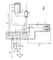
- Figure 1 illustrates an embodiment of the invention wherein the mixed feed is cooled by injection of boiler feedwater which is subsequently vaporized to process diluent steam.
- Figure 2 illustrates another embodiment of the invention wherein the mixed feed is cooled by indirect heat exchange in an exchanger that is external to the convection section of the furnace.
- Figure 3 illustrates yet another embodiment of the invention wherein the mixed feed is cooled by injection of a relatively cool hydrocarbon stream which may be a portion of the initial hydrocarbon feed as illustrated.
- mixed feed cooling is principally a function of the feed itself.
- an ethane mixed feed must be cooled more than, for example, a naphtha feed.
- a light gas oil feed will require less cooling.
- the mixed feed will typically be cooled by from 55°C to 220°C and then reheated to a temperature in the range between 565°C and 705°C just prior to introduction of the mixed feed to the cracking tubes.
- the mixed feed will typically be cooled by from 55°C to 140°C and then reheated to a temperature in the range between 540°C and 650°C.
- a pyrolysis unit designed for steam cracking heavy feeds such as gas oils comprised of a tubular fired furnace 1 having a radiant section 2 and convection section 3.
- Vertical cracking tubes 4 disposed within the radiant section are heated by floor burners 5.
- Hot combustion gas from the radiant section passes upwardly through the convection section where heat is successively absorbed from the combustion gas by convection coils 6, 7, 8, 9, 10, and 11.
- the pyrolysis unit additionally comprises primary quench exchanger 12 for rapidly cooling the cracked gases to stop pyrolysis side reactions and recover heat in the form of high pressure saturated steam collected in steam drum 13.
- boiler feedwater introduced through line 14 is preheated in convection coil 11 and passes to drum 13.
- Feedwater from the drum flows through line 15 to the primary quench exchanger where it is partially vaporized to steam and then returned to the steam drum.
- Saturated high pressure steam from the drum is passed through line 17 to convection coil 7 where it is superheated and discharged through line 18 to the plant steam system for use in turbine drives employed in the compression and separation of cracked gases.
- hydrocarbon gas oil boiling between 315°C and 565°C is introduced through line 120 and heated in convection coil 10.
- valves 121 and 123 are closed and valve 122 is open for flow of the preheated, initial hydrocarbon feed through line 124 where it joins process diluent steam introduced through line 125 and superheated in convection coil 8 to form a vaporized mixed feed.
- the mixed feed is heated in convection coils 9 and 6 to a temperature of 545°C, which is slightly below the incipient cracking temperature, and then introduced via line 19 to cracking tubes 4 in the radiant section of the furnace.
- the cracking tube outlet temperature is 845°C.
- valves 121 and 123 are open and valve 122 is closed.
- the feed is again introduced through line 120 and preheated in convection coil 10.
- the preheated, initial hydrocarbon feed flows through line 126 where it joins process diluent steam introduced through line 125 to form mixed feed.
- the process diluent steam introduced is less than half the amount customarily employed in ethane/propane pyrolysis.
- the mixed feed is heated in coil 8 to 620°C and then combined with boiler feedwater introduced through line 127 at a temperature of 120°C which vaporizes and cools the mixed feed by direct heat exchange.
- the resulting stream at a temperature of 510°C is then reheated in coils 9 and 6 to a temperature of 650°C, which is slightly below the incipient cracking temperature for this feed, and introduced via line 19 to cracking tubes 4 in the radiant section of the furnace.
- the vaporized boiler feedwater supple necessarilyments the process diluent steam introduced through line 125 so that the final steam/hydrocarbon ratio desired is present in the reheated mixed feed.
- the cracking tube outlet temperature is 880°C.
- valve 230 is open while valves 231 and 232 are closed to isolate heat exchanger 233 so that the mixed feed flows directly from coil 9 to coil 6 and then to the cracking tubes.
- valve 230 When ethane/propane is employed as feedstock in the scheme of Figure 2, valve 230 is closed while valves 231 and 232 are opened to permit cooling the mixed feed from coil 9 in heat exchanger 233 prior to reheating in coil 6. Stream temperatures are, for the most part, comparable to those recited in connection with Figure 1.
- valve 335 When gas oil is employed as feedstock in the scheme of Figure 3, valve 335 is closed and all of the feedstock introduced through line 320 is preheated in coil 10 and combined with process diluent steam introduced through line 325 and coil 8. When ethane/propane is employed as feedstock in the scheme of Figure 3, valve 335 is open and only a portion of the feed is preheated in coil 10.
- the preheated, initial hydrocarbon feed is then mixed with diluent steam introduced through line 325 and coil 8 and the resulting mixed feed cooled by hydrocarbon introduced through line 336 which, in this illustration, is the remaining portion of feed from line 320 that has by-passed coil 10.
- the cooled mixed feed is then reheated in coil 9 and 6.
Landscapes
- Chemical & Material Sciences (AREA)
- Oil, Petroleum & Natural Gas (AREA)
- Physics & Mathematics (AREA)
- Thermal Sciences (AREA)
- Engineering & Computer Science (AREA)
- Chemical Kinetics & Catalysis (AREA)
- General Chemical & Material Sciences (AREA)
- Organic Chemistry (AREA)
- Production Of Liquid Hydrocarbon Mixture For Refining Petroleum (AREA)
Applications Claiming Priority (2)
| Application Number | Priority Date | Filing Date | Title |
|---|---|---|---|
| US861963 | 1986-05-12 | ||
| US06/861,963 US4908121A (en) | 1986-05-12 | 1986-05-12 | Flexible feed pyrolysis process |
Publications (2)
| Publication Number | Publication Date |
|---|---|
| EP0245839A1 true EP0245839A1 (de) | 1987-11-19 |
| EP0245839B1 EP0245839B1 (de) | 1990-08-29 |
Family
ID=25337234
Family Applications (1)
| Application Number | Title | Priority Date | Filing Date |
|---|---|---|---|
| EP87106867A Expired - Lifetime EP0245839B1 (de) | 1986-05-12 | 1987-05-12 | Pyrolyseverfahren für flexible Einsätze |
Country Status (9)
| Country | Link |
|---|---|
| US (1) | US4908121A (de) |
| EP (1) | EP0245839B1 (de) |
| JP (1) | JPH0745669B2 (de) |
| KR (1) | KR870011226A (de) |
| CN (1) | CN1009833B (de) |
| CA (1) | CA1266060A (de) |
| DE (1) | DE3764536D1 (de) |
| ES (1) | ES2017667B3 (de) |
| IN (1) | IN169187B (de) |
Cited By (5)
| Publication number | Priority date | Publication date | Assignee | Title |
|---|---|---|---|---|
| RU2315800C2 (ru) * | 2006-03-03 | 2008-01-27 | Общество с ограниченной ответственностью "Томскнефтехим" (ООО "Томскнефтехим") | Способ получения низших олефинов |
| RU2318860C1 (ru) * | 2006-05-05 | 2008-03-10 | Общество с ограниченной ответственностью "Томскнефтехим" (ООО "Томскнефтехим") | Способ получения непредельных углеводородов |
| EP2653524A1 (de) * | 2012-04-17 | 2013-10-23 | Linde Aktiengesellschaft | Konvektionszone eines Spaltofens |
| WO2022069726A1 (de) | 2020-10-02 | 2022-04-07 | Basf Se | Wärmeintegration eines elektrisch beheizten reaktors |
| WO2023152162A1 (de) | 2022-02-09 | 2023-08-17 | Basf Se | Rückgewinnung der energie |
Families Citing this family (16)
| Publication number | Priority date | Publication date | Assignee | Title |
|---|---|---|---|---|
| US4696061A (en) * | 1983-12-28 | 1987-09-22 | Sperry Corporation | Acousto-optic R-F receiver which is tunable and has adjustable bandwidth |
| FR2631957B1 (fr) * | 1988-05-30 | 1990-08-31 | Bp Chimie Sa | Procede et appareillage de fabrication d'olefines et de diolefines par reaction de vapocraquage d'hydrocarbures controlee a l'aide d'un systeme comprenant un spectrophotometre infrarouge |
| US5078857A (en) * | 1988-09-13 | 1992-01-07 | Melton M Shannon | Delayed coking and heater therefor |
| JP3438308B2 (ja) * | 1994-03-31 | 2003-08-18 | ヤマハ株式会社 | 鍵盤楽器 |
| JP3336742B2 (ja) * | 1994-05-18 | 2002-10-21 | ヤマハ株式会社 | 鍵盤楽器 |
| US6533922B2 (en) * | 2001-03-09 | 2003-03-18 | Exxonmobil Research And Engineering Company | Process for reducing fouling in coking processes |
| US7339087B2 (en) * | 2001-03-15 | 2008-03-04 | Shell Oil Company | Pyrolysis |
| US7488459B2 (en) * | 2004-05-21 | 2009-02-10 | Exxonmobil Chemical Patents Inc. | Apparatus and process for controlling temperature of heated feed directed to a flash drum whose overhead provides feed for cracking |
| RU2265640C1 (ru) * | 2004-08-09 | 2005-12-10 | Общество с ограниченной ответственностью "Томскнефтехим" (ООО "Томскнефтехим") | Способ получения непредельных углеводородов |
| EP1683850A1 (de) * | 2005-01-20 | 2006-07-26 | Technip France | Verfahren zum Kracken von Kohlenwasserstoffeinsätzen mit einer Schwerfraktion |
| WO2007078269A2 (en) * | 2005-12-15 | 2007-07-12 | Ineos Usa Llc | Power recovery process |
| KR100999304B1 (ko) * | 2007-07-05 | 2010-12-08 | 주식회사 엘지화학 | 올레핀 제조용 탄화수소 열분해 방법 |
| US20090022635A1 (en) * | 2007-07-20 | 2009-01-22 | Selas Fluid Processing Corporation | High-performance cracker |
| US8083932B2 (en) * | 2007-08-23 | 2011-12-27 | Shell Oil Company | Process for producing lower olefins from hydrocarbon feedstock utilizing partial vaporization and separately controlled sets of pyrolysis coils |
| CA2946264A1 (en) * | 2016-10-25 | 2018-04-25 | Nova Chemicals Corporation | Use of semipermeable membranes in cracking coils |
| EP3415587B1 (de) * | 2017-06-16 | 2020-07-29 | Technip France | Spaltofensystem und verfahren zum spalten von erdölrückständen darin |
Citations (3)
| Publication number | Priority date | Publication date | Assignee | Title |
|---|---|---|---|---|
| FR1499590A (fr) * | 1966-11-03 | 1967-10-27 | Wellman Incandescent Furn Co | Procédé et réacteur pour la production de gaz combustibles |
| US4479869A (en) * | 1983-12-14 | 1984-10-30 | The M. W. Kellogg Company | Flexible feed pyrolysis process |
| FR2588564A1 (fr) * | 1985-10-10 | 1987-04-17 | Vyzk Ustav Chem Zarizeni | Appareil pour le cracking (ou craquage) d'hydrocarbures gazeux ou liquides |
Family Cites Families (9)
| Publication number | Priority date | Publication date | Assignee | Title |
|---|---|---|---|---|
| US2147399A (en) * | 1934-10-23 | 1939-02-14 | Power Patents Co | Process for cracking hydrocarbons |
| US2893941A (en) * | 1955-01-27 | 1959-07-07 | Exxon Research Engineering Co | Removing and preventing coke formation in tubular heaters by use of potassium carbonate |
| US3291573A (en) * | 1964-03-03 | 1966-12-13 | Hercules Inc | Apparatus for cracking hydrocarbons |
| US3580959A (en) * | 1966-10-12 | 1971-05-25 | Linde Ag | Process and apparatus for process control in cracking furnaces for the thermal cracking of hydrocarbons |
| US3557241A (en) * | 1968-10-16 | 1971-01-19 | Exxon Research Engineering Co | Decoking of onstream thermal cracking tubes with h20 and h2 |
| US3617493A (en) * | 1970-01-12 | 1971-11-02 | Exxon Research Engineering Co | Process for steam cracking crude oil |
| US4012457A (en) * | 1975-10-06 | 1977-03-15 | Shell Development Company | Thermal cracking method for the production of ethylene and propylene in a molten metal bath |
| DE2854061C2 (de) * | 1978-12-14 | 1987-04-02 | Linde Ag, 6200 Wiesbaden | Verfahren zum Vorwärmen von Kohlenwasserstoffen vor deren thermischer Spaltung sowie Spaltofen zur Durchführung des Verfahrens |
| US4264432A (en) * | 1979-10-02 | 1981-04-28 | Stone & Webster Engineering Corp. | Pre-heat vaporization system |
-
1986
- 1986-05-12 US US06/861,963 patent/US4908121A/en not_active Expired - Fee Related
-
1987
- 1987-03-16 CA CA000532141A patent/CA1266060A/en not_active Expired - Lifetime
- 1987-03-19 IN IN240/DEL/87A patent/IN169187B/en unknown
- 1987-05-08 JP JP62112241A patent/JPH0745669B2/ja not_active Expired - Lifetime
- 1987-05-12 EP EP87106867A patent/EP0245839B1/de not_active Expired - Lifetime
- 1987-05-12 KR KR870004664A patent/KR870011226A/ko not_active Withdrawn
- 1987-05-12 CN CN87103525A patent/CN1009833B/zh not_active Expired
- 1987-05-12 DE DE8787106867T patent/DE3764536D1/de not_active Expired - Lifetime
- 1987-05-12 ES ES87106867T patent/ES2017667B3/es not_active Expired - Lifetime
Patent Citations (3)
| Publication number | Priority date | Publication date | Assignee | Title |
|---|---|---|---|---|
| FR1499590A (fr) * | 1966-11-03 | 1967-10-27 | Wellman Incandescent Furn Co | Procédé et réacteur pour la production de gaz combustibles |
| US4479869A (en) * | 1983-12-14 | 1984-10-30 | The M. W. Kellogg Company | Flexible feed pyrolysis process |
| FR2588564A1 (fr) * | 1985-10-10 | 1987-04-17 | Vyzk Ustav Chem Zarizeni | Appareil pour le cracking (ou craquage) d'hydrocarbures gazeux ou liquides |
Cited By (6)
| Publication number | Priority date | Publication date | Assignee | Title |
|---|---|---|---|---|
| RU2315800C2 (ru) * | 2006-03-03 | 2008-01-27 | Общество с ограниченной ответственностью "Томскнефтехим" (ООО "Томскнефтехим") | Способ получения низших олефинов |
| RU2318860C1 (ru) * | 2006-05-05 | 2008-03-10 | Общество с ограниченной ответственностью "Томскнефтехим" (ООО "Томскнефтехим") | Способ получения непредельных углеводородов |
| EP2653524A1 (de) * | 2012-04-17 | 2013-10-23 | Linde Aktiengesellschaft | Konvektionszone eines Spaltofens |
| RU2611008C2 (ru) * | 2012-04-17 | 2017-02-17 | Линде Акциенгезелльшафт | Зона конвекции печи для крекинга |
| WO2022069726A1 (de) | 2020-10-02 | 2022-04-07 | Basf Se | Wärmeintegration eines elektrisch beheizten reaktors |
| WO2023152162A1 (de) | 2022-02-09 | 2023-08-17 | Basf Se | Rückgewinnung der energie |
Also Published As
| Publication number | Publication date |
|---|---|
| JPS62267397A (ja) | 1987-11-20 |
| US4908121A (en) | 1990-03-13 |
| CA1266060A (en) | 1990-02-20 |
| ES2017667B3 (es) | 1991-03-01 |
| CN87103525A (zh) | 1987-11-25 |
| EP0245839B1 (de) | 1990-08-29 |
| KR870011226A (ko) | 1987-12-21 |
| CN1009833B (zh) | 1990-10-03 |
| JPH0745669B2 (ja) | 1995-05-17 |
| IN169187B (de) | 1991-09-14 |
| DE3764536D1 (de) | 1990-10-04 |
Similar Documents
| Publication | Publication Date | Title |
|---|---|---|
| US4908121A (en) | Flexible feed pyrolysis process | |
| US4479869A (en) | Flexible feed pyrolysis process | |
| US4361478A (en) | Method of preheating hydrocarbons for thermal cracking | |
| TWI408221B (zh) | 利用全原油原料之烯烴生產 | |
| US3407789A (en) | Heating apparatus and process | |
| CA1207266A (en) | Process and apparatus for thermally cracking hydrocarbons | |
| US7977524B2 (en) | Process for decoking a furnace for cracking a hydrocarbon feed | |
| CA2728567C (en) | Process for the on-stream decoking of a furnace for cracking a hydrocarbon feed | |
| KR20220088691A (ko) | 분해로 시스템 및 그의 탄화수소 공급원료를 분해하기 위한 방법 | |
| US10899970B2 (en) | Pyrolysis product compression | |
| US5139650A (en) | Method and installation for steam cracking hydrocarbons | |
| JPS6212206B2 (de) | ||
| EP0030446B1 (de) | Verfahren zur Spaltung von Kohlenwasserstoffen | |
| EP4496868A1 (de) | Spalterhitzer mit niedriger co2-emission und wasserstoffimport zur olefinherstellung | |
| US9181495B2 (en) | Convection zone of a cracking furnace | |
| JPH06116568A (ja) | オレフィン製造の為の分離炉に於ける処理制御方法 | |
| US20250026987A1 (en) | Electric adiabatic heater for olefin production | |
| EP1509582A1 (de) | Verbessertes cracken von kohlenwasserstoffen | |
| SU1430397A1 (ru) | Трубчата печь пиролиза | |
| US1992616A (en) | Art of cracking hydrocarbons |
Legal Events
| Date | Code | Title | Description |
|---|---|---|---|
| PUAI | Public reference made under article 153(3) epc to a published international application that has entered the european phase |
Free format text: ORIGINAL CODE: 0009012 |
|
| AK | Designated contracting states |
Kind code of ref document: A1 Designated state(s): BE DE ES FR GB IT |
|
| 17P | Request for examination filed |
Effective date: 19871228 |
|
| 17Q | First examination report despatched |
Effective date: 19880715 |
|
| GRAA | (expected) grant |
Free format text: ORIGINAL CODE: 0009210 |
|
| AK | Designated contracting states |
Kind code of ref document: B1 Designated state(s): BE DE ES FR GB IT |
|
| ITF | It: translation for a ep patent filed | ||
| REF | Corresponds to: |
Ref document number: 3764536 Country of ref document: DE Date of ref document: 19901004 |
|
| ET | Fr: translation filed | ||
| ITTA | It: last paid annual fee | ||
| PLBE | No opposition filed within time limit |
Free format text: ORIGINAL CODE: 0009261 |
|
| STAA | Information on the status of an ep patent application or granted ep patent |
Free format text: STATUS: NO OPPOSITION FILED WITHIN TIME LIMIT |
|
| 26N | No opposition filed | ||
| PGFP | Annual fee paid to national office [announced via postgrant information from national office to epo] |
Ref country code: GB Payment date: 19980403 Year of fee payment: 12 |
|
| PGFP | Annual fee paid to national office [announced via postgrant information from national office to epo] |
Ref country code: FR Payment date: 19980508 Year of fee payment: 12 |
|
| PGFP | Annual fee paid to national office [announced via postgrant information from national office to epo] |
Ref country code: ES Payment date: 19980522 Year of fee payment: 12 |
|
| PGFP | Annual fee paid to national office [announced via postgrant information from national office to epo] |
Ref country code: DE Payment date: 19980529 Year of fee payment: 12 |
|
| PGFP | Annual fee paid to national office [announced via postgrant information from national office to epo] |
Ref country code: BE Payment date: 19980609 Year of fee payment: 12 |
|
| PG25 | Lapsed in a contracting state [announced via postgrant information from national office to epo] |
Ref country code: GB Free format text: LAPSE BECAUSE OF NON-PAYMENT OF DUE FEES Effective date: 19990512 |
|
| PG25 | Lapsed in a contracting state [announced via postgrant information from national office to epo] |
Ref country code: ES Free format text: LAPSE BECAUSE OF NON-PAYMENT OF DUE FEES Effective date: 19990513 |
|
| PG25 | Lapsed in a contracting state [announced via postgrant information from national office to epo] |
Ref country code: BE Free format text: LAPSE BECAUSE OF NON-PAYMENT OF DUE FEES Effective date: 19990531 |
|
| BERE | Be: lapsed |
Owner name: THE M. W. KELLOGG CY Effective date: 19990531 |
|
| GBPC | Gb: european patent ceased through non-payment of renewal fee |
Effective date: 19990512 |
|
| PG25 | Lapsed in a contracting state [announced via postgrant information from national office to epo] |
Ref country code: FR Free format text: LAPSE BECAUSE OF NON-PAYMENT OF DUE FEES Effective date: 20000131 |
|
| PG25 | Lapsed in a contracting state [announced via postgrant information from national office to epo] |
Ref country code: DE Free format text: LAPSE BECAUSE OF NON-PAYMENT OF DUE FEES Effective date: 20000301 |
|
| REG | Reference to a national code |
Ref country code: FR Ref legal event code: ST |
|
| REG | Reference to a national code |
Ref country code: ES Ref legal event code: FD2A Effective date: 20010503 |
|
| PG25 | Lapsed in a contracting state [announced via postgrant information from national office to epo] |
Ref country code: IT Free format text: LAPSE BECAUSE OF NON-PAYMENT OF DUE FEES;WARNING: LAPSES OF ITALIAN PATENTS WITH EFFECTIVE DATE BEFORE 2007 MAY HAVE OCCURRED AT ANY TIME BEFORE 2007. THE CORRECT EFFECTIVE DATE MAY BE DIFFERENT FROM THE ONE RECORDED. Effective date: 20050512 |