EP0245827A2 - Apparatus for adjusting the temperature of devices, especially of tools - Google Patents
Apparatus for adjusting the temperature of devices, especially of tools Download PDFInfo
- Publication number
- EP0245827A2 EP0245827A2 EP87106826A EP87106826A EP0245827A2 EP 0245827 A2 EP0245827 A2 EP 0245827A2 EP 87106826 A EP87106826 A EP 87106826A EP 87106826 A EP87106826 A EP 87106826A EP 0245827 A2 EP0245827 A2 EP 0245827A2
- Authority
- EP
- European Patent Office
- Prior art keywords
- temperature
- liquid
- reference signal
- output
- heating
- Prior art date
- Legal status (The legal status is an assumption and is not a legal conclusion. Google has not performed a legal analysis and makes no representation as to the accuracy of the status listed.)
- Ceased
Links
Images

Classifications
-
- F—MECHANICAL ENGINEERING; LIGHTING; HEATING; WEAPONS; BLASTING
- F28—HEAT EXCHANGE IN GENERAL
- F28D—HEAT-EXCHANGE APPARATUS, NOT PROVIDED FOR IN ANOTHER SUBCLASS, IN WHICH THE HEAT-EXCHANGE MEDIA DO NOT COME INTO DIRECT CONTACT
- F28D15/00—Heat-exchange apparatus with the intermediate heat-transfer medium in closed tubes passing into or through the conduit walls ; Heat-exchange apparatus employing intermediate heat-transfer medium or bodies
-
- B—PERFORMING OPERATIONS; TRANSPORTING
- B29—WORKING OF PLASTICS; WORKING OF SUBSTANCES IN A PLASTIC STATE IN GENERAL
- B29C—SHAPING OR JOINING OF PLASTICS; SHAPING OF MATERIAL IN A PLASTIC STATE, NOT OTHERWISE PROVIDED FOR; AFTER-TREATMENT OF THE SHAPED PRODUCTS, e.g. REPAIRING
- B29C35/00—Heating, cooling or curing, e.g. crosslinking or vulcanising; Apparatus therefor
- B29C35/007—Tempering units for temperature control of moulds or cores, e.g. comprising heat exchangers, controlled valves, temperature-controlled circuits for fluids
-
- B—PERFORMING OPERATIONS; TRANSPORTING
- B29—WORKING OF PLASTICS; WORKING OF SUBSTANCES IN A PLASTIC STATE IN GENERAL
- B29C—SHAPING OR JOINING OF PLASTICS; SHAPING OF MATERIAL IN A PLASTIC STATE, NOT OTHERWISE PROVIDED FOR; AFTER-TREATMENT OF THE SHAPED PRODUCTS, e.g. REPAIRING
- B29C45/00—Injection moulding, i.e. forcing the required volume of moulding material through a nozzle into a closed mould; Apparatus therefor
- B29C45/17—Component parts, details or accessories; Auxiliary operations
- B29C45/72—Heating or cooling
- B29C45/73—Heating or cooling of the mould
- B29C45/7306—Control circuits therefor
-
- F—MECHANICAL ENGINEERING; LIGHTING; HEATING; WEAPONS; BLASTING
- F28—HEAT EXCHANGE IN GENERAL
- F28D—HEAT-EXCHANGE APPARATUS, NOT PROVIDED FOR IN ANOTHER SUBCLASS, IN WHICH THE HEAT-EXCHANGE MEDIA DO NOT COME INTO DIRECT CONTACT
- F28D1/00—Heat-exchange apparatus having stationary conduit assemblies for one heat-exchange medium only, the media being in contact with different sides of the conduit wall, in which the other heat-exchange medium is a large body of fluid, e.g. domestic or motor car radiators
- F28D1/02—Heat-exchange apparatus having stationary conduit assemblies for one heat-exchange medium only, the media being in contact with different sides of the conduit wall, in which the other heat-exchange medium is a large body of fluid, e.g. domestic or motor car radiators with heat-exchange conduits immersed in the body of fluid
- F28D1/0233—Heat-exchange apparatus having stationary conduit assemblies for one heat-exchange medium only, the media being in contact with different sides of the conduit wall, in which the other heat-exchange medium is a large body of fluid, e.g. domestic or motor car radiators with heat-exchange conduits immersed in the body of fluid with air flow channels
- F28D1/024—Heat-exchange apparatus having stationary conduit assemblies for one heat-exchange medium only, the media being in contact with different sides of the conduit wall, in which the other heat-exchange medium is a large body of fluid, e.g. domestic or motor car radiators with heat-exchange conduits immersed in the body of fluid with air flow channels with an air driving element
-
- F—MECHANICAL ENGINEERING; LIGHTING; HEATING; WEAPONS; BLASTING
- F28—HEAT EXCHANGE IN GENERAL
- F28F—DETAILS OF HEAT-EXCHANGE AND HEAT-TRANSFER APPARATUS, OF GENERAL APPLICATION
- F28F27/00—Control arrangements or safety devices specially adapted for heat-exchange or heat-transfer apparatus
-
- G—PHYSICS
- G05—CONTROLLING; REGULATING
- G05D—SYSTEMS FOR CONTROLLING OR REGULATING NON-ELECTRIC VARIABLES
- G05D23/00—Control of temperature
- G05D23/19—Control of temperature characterised by the use of electric means
- G05D23/1919—Control of temperature characterised by the use of electric means characterised by the type of controller
-
- G—PHYSICS
- G05—CONTROLLING; REGULATING
- G05D—SYSTEMS FOR CONTROLLING OR REGULATING NON-ELECTRIC VARIABLES
- G05D23/00—Control of temperature
- G05D23/19—Control of temperature characterised by the use of electric means
- G05D23/20—Control of temperature characterised by the use of electric means with sensing elements having variation of electric or magnetic properties with change of temperature
- G05D23/24—Control of temperature characterised by the use of electric means with sensing elements having variation of electric or magnetic properties with change of temperature the sensing element having a resistance varying with temperature, e.g. a thermistor
-
- F—MECHANICAL ENGINEERING; LIGHTING; HEATING; WEAPONS; BLASTING
- F28—HEAT EXCHANGE IN GENERAL
- F28D—HEAT-EXCHANGE APPARATUS, NOT PROVIDED FOR IN ANOTHER SUBCLASS, IN WHICH THE HEAT-EXCHANGE MEDIA DO NOT COME INTO DIRECT CONTACT
- F28D21/00—Heat-exchange apparatus not covered by any of the groups F28D1/00 - F28D20/00
- F28D2021/0019—Other heat exchangers for particular applications; Heat exchange systems not otherwise provided for
- F28D2021/0077—Other heat exchangers for particular applications; Heat exchange systems not otherwise provided for for tempering, e.g. with cooling or heating circuits for temperature control of elements
Definitions
- the invention relates to a device for adjusting the temperature of devices, in particular tools, by circulating a heat-transferring liquid, this device comprising a container storing the liquid, a heating element in contact with the liquid, a pump which allows the liquid to circulate through the channel of the device, a temperature sensor measuring the temperature of the liquid, a temperature control unit which engages in the power supply of the radiator and is connected to the temperature sensor, and to a reference signal transmitter determining the desired temperature, and furthermore has a construction unit which ensures the cooling of the device, the reference signal transmitter being connected to an input of a difference former is.
- the designers of the devices have made sure that the medium used for temperature control, in most cases oil (in some cases water), reaches the corresponding parts of the device and can exert its effect there by forming appropriate channels.
- the regulation of the temperature is ensured with the aid of devices which allow a predetermined amount of liquid to flow through the channels of the device at a certain constant flow rate.
- the path of the liquid leads via the radiator, by means of which the liquid is heated, a pipe coil through which a cooling liquid flows is also inserted into the liquid path, with the aid of which the liquid can be cooled.
- the temperature of the liquid emerging from the control device is generally used for the temperature control, and the temperature prevailing inside the tool is inferred from this.
- the most precise regulation could be ensured by temperature sensors attached to the body of the tool or device, for the arrangement of such
- one temperature control device is even connected to several tools per shift, whereby the calibration of this device for the various temperature sensors arranged in it can only be solved in a complicated manner.
- the number of temperature control devices to be connected to the device must correspond to the number of different temperature zones to be trained.
- Each temperature control device is suitable for maintaining only a single predetermined temperature and is provided with an outlet and a return flow connection.
- the individual desired temperatures can be set individually with the temperature control devices. The possibility described here carries certain dangers. If the different temperatures are not set precisely or are possibly missed, unnecessarily large temperature differences can arise between the various parts of the same device to be controlled, which lead to the formation of internal stresses and to a deterioration in the quality of the tool. Experience has shown that it is not practical to maintain a temperature difference of more than ⁇ 20 ° C between the different parts of an average tool.
- the above-mentioned properties can be found in most temperature regulators from the Swiss company REGLOPLAS AG, for example in the types 15S, 150 KL, 150.
- the cooling realized by means of the cooling liquid circulated in a closed coil can be regarded as disadvantageous, since during the heating following cooling, the liquid in the coil must also be heated, which means a superfluous expenditure of energy and increases the time required for the regulation.
- the basic problem to be solved with the invention is the perfection of the devices regulating the temperature of devices, primarily the reduction of the tolerance range while maintaining the desired temperature.
- the object to be achieved with the invention is also to create a device which is easier to use in practice, and to reduce the control time constant and to minimize the energy losses.
- the invention is based on the knowledge that the actual temperature of the devices can be approximated with the average of the temperatures of the emerging and the returning liquid and this average can serve as the basis for the temperature control.
- the effectiveness of the regulation solved in this way can be further increased in that the cooling is not achieved with a tube coil through which the cooling liquid flows and which is arranged in the path of the medium, but with such a heat exchanger in which the cooling is carried out by air conveyed by a fan is secured.
- a device for adjusting the temperature of devices, in particular tools Circulation of a heat-transferring liquid comprising a liquid-storing container, a heating element in contact with the liquid, a pump which allows the liquid to circulate through a channel of the device designed for this purpose, a temperature sensor measuring the temperature of the liquid and a power supply of the radiator intervening temperature control unit connected to the temperature sensor and to a reference signal transmitter determining the desired temperature, furthermore having a construction unit securing the cooling of the device, the reference signal transmitter being connected to an input of a difference former and, according to the invention, in one which circulates the liquid closed flow circuit a heat exchanger, which is connected to a fan, is inserted, that two further separate the temperature of the exiting and returning Liquid-detecting temperature sensors and in the temperature control unit a mean value generator simulating the temperature of the device based on the signals of the two temperature sensors are provided, the output of the mean value generator being connected to the other input of the difference former and the output of the difference former
- the heat exchanger enables a horizontally directed air flow, the vertically directed circulation is hindered by the use of horizontal fins.
- one side of the heat exchanger is connected to a funnel which widens upwards and is open at the top, and the other side is connected to a fan which generates a horizontal air flow.
- the above-mentioned average (average value) is used as the basis for the control.
- this mean value can be influenced to a lesser extent with knowledge of some empirical values and the actual ambient temperature.
- a plurality of heating / cooling units are arranged in a common construction housing, each of which is assigned a control unit.
- a single device is sufficient to regulate the temperature of the tool, for example by connecting the fixed part and the movable part at the same time.
- the temperature control device designed according to the invention enables faster reaching and more precise maintenance of the operating temperature, its energy requirement is lower, no cooling water connection is required, the use of the device according to the invention excludes subjective setting errors, the device adapts flexibly to the operating conditions, since the conventional devices, there is no need to connect multiple devices to a single tool.
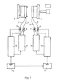
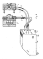
- FIG. 1 An injection molding tool is shown schematically in FIG. 1, the temperature of which can be regulated to a predetermined value using the device designed according to the invention.
- the tool consists of two parts, a fixed side 1 and a moving side 2, in the interior of which channels for the liquid used for heating or cooling are formed, which are connected via connecting pieces to inlet lines 3 and 4 and to outlet lines 5 and 6 .
- the fluid path closes after the insertion of temperature sensors 7, 8 or 9, 10, each via a heating circuit cooling unit 11 or 12 of the same design, which has the necessary heating and cooling of the liquid and has a closed flow circuit.
- the desired temperature of the fixed side 1 of the tool can be determined using of a reference signal transmitter 13 can be set, while the temperature of the moving side 2 of the tool can be set by means of a reference signal transmitter 14.
- a control unit 15 or 16 is connected to the heating-cooling unit 11 or 12, which is connected to the reference signal transmitters 13 or 14 and the temperature sensors 7, 8 or 9, 10.
- there can be at most a difference of 20-25 ° C between the temperatures of the fixed side 1 and the moving side 2 therefore only one of the two reference signal transmitters 13 and 14 can be set independently of the other.
- the reference signal generator 13 receives the output signal of the reference signal generator 14 and the reference signal generator 13 only allows the temperature of the control unit 15 which sets the temperature of the fixed side 1 to be within the limits of, for example, ⁇ 20 ° C. in relation to that to be set using the control unit 16 Setting the temperature.
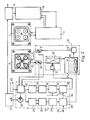
- the arrangement shown in FIG. 1 was repeated schematically in FIG. 2, but the internal structure of the heating-cooling unit 12 assigned to the moving side 2 and the control unit 16 are also illustrated in more detail.
- the fixed side 1 and the moving side 2 of the tool are shown here on the front of the work surface. It can be clearly seen from the figure that the four nests of the tool are completely surrounded by a channel which receives the heating / cooling medium.
- the heating-cooling unit 12 In the heating-cooling unit 12 are an oil tank 17, on the bottom of which a radiator 18, a circulation pump 19 inserted into the outlet line of the oil container 17, a heat exchanger 20 switched on in the line returning from the tool and a fan 21 which triggers the heat exchange are arranged. Oil circulates in the closed flow circuit with the aid of the circulation pump 19 in accordance with a constant flow volume. Pressure sensors (not shown in the figure) are arranged on the inlet and outlet connections of the circuit, which, with the aid of appropriate safety circuits, ensure that the oil is only circulated under approved pressure conditions. In a similar manner, a level detector arranged in the oil container 17 indicates when the oil level assumes a value outside of permitted limits.
- control unit 16 receives the temperature reference signal set by the reference signal generator 14, while an averager 22 arranged in the control unit 16 receives the outflow and inflow temperature signals of the moving side 2 from the temperature sensors 9, 10 and the signal about those prevailing in the vicinity of the tool Receives temperature from a temperature sensor 23.
- the output of the reference signal generator 14 and the output of the mean value generator 22 are each connected to an input of a difference generator 24, the output of which branches in two directions.
- the branches are sensitive to the sign of the differential signal appearing at the output, and only one of these two branches functions at a time.
- the branch belonging to the negative sign (ie if the required temperature is below the actual one) has an integrator 25, a comparator 26 connected to it in chain, a monostable multivibrator 27 and one by switching it off gear-controlled switch 28, the latter switching the mains voltage to the radiator 18 via a mains connection 29.
- the branch belonging to the positive sign has a similar structure and has an integrator 30, a comparator 31, a monostable multivibrator 32 and a controlled switch 33, the controlled switch 33 controlling the function of the fan 21 with its output.
- the monostable multivibrator 32 is synchronized with the network, each start of the pulse begins at the zero crossing of the network signal and ensures a signal with a complete wave for the fan 21 at all times.
- the synchronous run is symbolically illustrated in FIG. 2 by line 34. Both branches give pulses of a certain length to the actuated means with a frequency proportional to the size of the difference signal, i.e. to the radiator 18 or the fan 21.
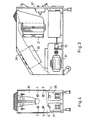
- FIGS. 3 and 4 illustrate the construction of the device according to the invention.
- the device is provided with a rollable, or in a given position attachable construction housing 35, in which two uniform heating-cooling units 11, 12 are arranged side by side in such a way that their oil tank 17 and 36 is below and above the oil tank 17, the associated heat exchanger 20 are arranged with the fan 21 and next to it the other heat exchanger and fan belonging to the oil container 36 and not shown separately in the figure.
- the motor 37 drives the circulation pump 19.
- the construction housing 35 is designed with an inclined end wall and the electronic units are arranged in a block formed underneath.
- the construction housing 35 also has a rear wall 40, on which the connections of the inlet lines 3, 4 and the outlet line lines 5, 6 are formed.
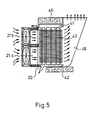
- the heat exchanger 20 is designed for a horizontal air flow, i.e. between an upper manifold 41 and a lower manifold 42, a plurality of vertical connecting pipes 43 are attached, to which a large number of horizontal lamellae are fastened vertically.
- the ventilation is ensured by two fans 21a and 21b arranged one above the other, which let the air flow between the horizontal fins 44.
- the outflowing air arrives in a funnel 45 which widens upwards and is open at the top and allows the air to escape upwards into the open.
- the heat exchanger 20 is completely surrounded by a heat insulation sleeve 46.
- the schematically illustrated construction is advantageous on the one hand, because when the fans are in a standing state, no natural cooling can develop, the heat loss is minimal.
- the permanent connection of the heat exchanger 20 thus does not cause any significant heat loss in heating operation, but intensive cooling begins when the fans are switched on.
- Another advantage is that the horizontal front air intake and the vertical exhaust allow two or more units to be arranged side by side.
- FIG. 6 shows the device according to the invention in a perspective view and the injection molding tool connected to it, the latter being drawn on an enlarged scale for better illustration.
- the device according to the invention functions as follows wise:
- the temperatures of the fixed side 1 and the moving side 2 of the injection mold are determined by the technology of the injection molding.
- the basic task of the device according to the invention is to ensure that the tool reaches this temperature as quickly and precisely as possible when it is started up, and maintains it within narrow tolerance limits during injection molding despite the changing thermal load.
- the double design enables the connection of both tool sides and that the closed circulation circuit of the oil also includes both the possibility of heating and the possibility of cooling.
- the averager 22 determines the simulated temperature T sz of the tool using this equation, and derives the value of k from the signal from the temperature sensor 23.
- the output signal of the difference former 24 assumes a positive or negative sign, while the size of these output signals depends on the size of the difference. If this output signal has a negative sign, ie the tool has not yet reached the desired temperature, heating is required and the branch controlling the radiator 18 starts to operate.
- a sawtooth pulse that increases in proportion to the difference appears.
- the monostable multivibrator 27 When it reaches a reference value that determines the threshold value of the comparator 26, the monostable multivibrator 27 switches on the heating of the radiator 18 for a predetermined period of time. In the case of a large difference signal, the monostable multivibrator 27 receives a new control pulse before the tipping back, whereby constant heating is achieved. In addition to the correct selection of the time constant and the threshold values, the control can be made extremely effective with the lower values of the difference values.
- the output signal of the difference former 24 changes its sign, the heating branch switches off and the fan 21 comes into operation by completely similar regulation.
- the intensive heat exchange quickly reduces the temperature of the circulating oil and removes the excess heat from the tool.
- the reference signal generator 13 of the other circuit already receives its reference signal from the reference signal generator 14 of the first circuit, relative to which it can only make changes within predetermined limits. For example, if a temperature of 80 ° C was set on the reference signal transmitter 14, the ⁇ 20 ° C scale of the reference signal transmitter 13 only allows the temperature of the other circuit to be set within the limits of 60 and 80 ° C. This prevents dangerously high temperature differences from forming in the tool, which at the same time enables the selection of technologies which require temperature differences of a predetermined size.
- the control reference signal of the reference signal generator 14 can be branched off to the reference signal generator 13 to other reference signal generators, which indicates the possibility of connecting further circuits.
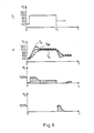
- the independent variable of Fig. 7 is the time axis.
- the reference signal T j is set to 80 ° C.
- the radiator 18 then switches on and the temperatures T a and T b change according to the figure.
- the peculiarity of the control is that the temperature T a greatly exceeds the value T j , so the tool heats up in a relatively short time.
- This Circumstances are indicated by an indicator connected to the difference generator 24.
- the course of the heating power P f is also illustrated in the figure.
- the heating works with 100% output in the initial period, then it drops and takes on an ever decreasing value.
- the curve P sz shows the heat absorption or heat emission of the tool, which due to the various losses does not match the curves of the heating power P f and the cooling power P h .
- the arrow C1 on the curve P sz shows a long cycle time, while the arrow C2 illustrates a short cycle time.
- the arrow F indicates the heating and the arrow W indicates the operating period (injection molding).
- the conditions of the cooling and the course of the cooling power P h can be followed with the aid of FIG. 7.
- the temperature difference T a - T b is proportional to the amount of heat removed.
- the thickness of the diagram T sz shows the change range of the temperature of the tool. The control is so effective that the temperature of the mold changes by no more than ⁇ 2 ° C, even during the injection molding operation that places the greatest heat load.
- the desired temperature can be reached and maintained quickly without using temperature sensors to be inserted into the tool, heating takes place in a considerably shorter time, since the temperature of the heating oil is allowed to be above the desired temperature of the tool and the temperature is maintained has an extremely low tolerance during control.
Abstract
Description
Die Erfindung betrifft eine Vorrichtung zum Einstellen der Temperatur von Geräten, insbesondere Werkzeugen durch Zirkulation einer wärmeübertragenden Flüssigkeit, wobei diese Vorrichtung einen die Flüssigkeit speichernden Behälter, einen mit der Flüssigkeit in Kontakt stehenden Heizkörper, eine die Flüssigkeit durch den Kanal des Gerätes zirkulieren lassende Pumpe, einen die Temperatur der Flüssigkeit messenden Temperaturfühler, eine in die Stromversorgung des Heizkörpers eingreifende und mit dem Temperaturfühler, sowie mit einem die gewünschte Temperatur bestimmenden Referenzsignalgeber verbundene Temperaturregelungseinheit, desweiteren eine die Kühlung des Gerätes sichernde Konstruktionseinheit aufweist, wobei der Referenzsignalgeber mit einem Eingang eines Differenzbildners verbunden ist.The invention relates to a device for adjusting the temperature of devices, in particular tools, by circulating a heat-transferring liquid, this device comprising a container storing the liquid, a heating element in contact with the liquid, a pump which allows the liquid to circulate through the channel of the device, a temperature sensor measuring the temperature of the liquid, a temperature control unit which engages in the power supply of the radiator and is connected to the temperature sensor, and to a reference signal transmitter determining the desired temperature, and furthermore has a construction unit which ensures the cooling of the device, the reference signal transmitter being connected to an input of a difference former is.
Es ist allgemein bekannt, dass zur Sicherung der entsprechenden Funktion von Spritzgiess- und Pressgiesswerkzeugen, Strangpressen, Mischern usw. dafür gesorgt werden muss, dass die Geräte oder bestimmte Teile derer eine durch die jeweilige Technologie vorgegebene Temperatur aufweisen. Zur Erreichung der erforderlichen Temperatur sind die Geräte zuerst aufzuheizen, dann während des Betriebes sind zur Einhaltung der Temperatur gegebenenfalls Heizung, andernfalls Kühlung erforderlich. Bei der Öffnung des Gerätes (Werkzeuges) tritt infolge der niederen Umgebungstemperatur ein Wärmeverlust auf, bei der Zuführung des Pressgutes dagegen wird das Gerät durch die höhere Temperatur des Materials aufgeheizt. Neben diesen Übergangseffekten tritt ausserdem ein ständiger Wärmeverlust auf, dessen Grösse von dem Temperaturunterschied zwischen der Umgebungstemperatur und der Betriebstempera tur, der Mikroumgebung und einer Reihe anderer Faktoren abhängt. Die Vervollkommnung der Technologien in der Kunststoffindustrie und die ständig steigenden Qualitätsanforderungen an die hergestellten Produkte erfordern nicht nur, dass das Werkzeug die vorgeschriebene Temperatur in immer kleineren Toleranzgrenzen hält, sondern, dass einzelne Teile des Werkzeuges, zum Beispiel der feststehende Teil und der bewegbare Teil, gegebenenfalls innerhalb dieser ein jeweils abgesonderter Bereich auch unter einer voneinander abweichenden Betriebstemperatur betrieben werden soll.It is generally known that in order to ensure the corresponding function of injection molding and die casting tools, extrusion presses, mixers, etc., it must be ensured that the devices or certain parts of them have a temperature specified by the respective technology. To achieve the required temperature, the devices must first be heated up, then heating may be required during operation to maintain the temperature, otherwise cooling is required. When the device (tool) is opened, there is a loss of heat due to the low ambient temperature, but when the material to be pressed is fed, the device is heated by the higher temperature of the material. In addition to these transition effects, there is also a constant loss of heat, the size of which depends on the temperature difference between the ambient temperature and the operating temperature ture that depends on the microenvironment and a number of other factors. The perfection of technologies in the plastics industry and the constantly increasing quality requirements for the manufactured products not only require that the tool maintains the prescribed temperature within ever smaller tolerance limits, but that individual parts of the tool, for example the fixed part and the movable part, if necessary, a separate area within this should also be operated at a different operating temperature.
Zur Einhaltung der vorgegebenen Temperatur haben die Konstrukteure der Geräte durch Ausbildung entsprechender Kanäle dafür gesorgt, dass das zur Temperaturregelung verwendete Medium, in den meisten Fällen Öl (in einigen Fällen Wasser) an die entsprechenden Teile des Gerätes gelangen und dort seine Wirkung ausüben kann.In order to maintain the specified temperature, the designers of the devices have made sure that the medium used for temperature control, in most cases oil (in some cases water), reaches the corresponding parts of the device and can exert its effect there by forming appropriate channels.
Die Regelung der Temperatur wird mit Hilfe solcher Vorrichtungen gesichert, die eine vorgegebene Flüssigkeitsmenge mit einer bestimmten konstanten Strömungsgeschwindigkeit durch die Kanäle des Gerätes durchströmen lassen. Der Weg der Flüssigkeit führt über den Heizkörper, durch dessen Einschaltung die Flüssigkeit erwärmt wird, in den Flüssigkeitsweg ist weiterhin eine von einer Kühlflüssigkeit durchströmte Rohrschlange eingefügt, mit deren Hilfe die Flüssigkeit kühlbar ist.The regulation of the temperature is ensured with the aid of devices which allow a predetermined amount of liquid to flow through the channels of the device at a certain constant flow rate. The path of the liquid leads via the radiator, by means of which the liquid is heated, a pipe coil through which a cooling liquid flows is also inserted into the liquid path, with the aid of which the liquid can be cooled.
Für die Temperaturregelung wird im allgemeinen die Temperatur der aus der Regelungseinrichtung austretenden Flüssigkeit ausgenutzt, und davon ausgehend wird auf die im Innern des Werkzeuges herrschende Temperatur geschlussfolgert. Theoretisch könnte die genaueste Regelung durch an den Körper des Werkzeuges oder Gerätes befestigte Temperaturfühler gesichert werden, zur Anordnung derartiger Temperaturfühler besteht jedoch bei den meisten Werkzeugen keine Möglichkeit, desweiteren ist eine Temperaturregelungseinrichtung sogar je Schicht an mehrere Werkzeuge angeschlossen, wobei die Eichung dieser Einrichtung zu den in diesen angeordneten verschiedenen Temperaturfühlern nur auf komplizierte Weise gelöst werden kann.The temperature of the liquid emerging from the control device is generally used for the temperature control, and the temperature prevailing inside the tool is inferred from this. Theoretically, the most precise regulation could be ensured by temperature sensors attached to the body of the tool or device, for the arrangement of such However, there is no possibility of temperature sensors in most tools. Furthermore, one temperature control device is even connected to several tools per shift, whereby the calibration of this device for the various temperature sensors arranged in it can only be solved in a complicated manner.
In der Praxis hat sich aus diesen Gründen die Anwendung von unmittelbaren (direkten) Temperaturfühlern nicht verbreitet. Die auf der Messung der Temperatur der austretenden Flüssigkeit beruhende Regelung kann die Einstellung der Temperatur des Werkzeuges nur mit einem relativ grossen Fehler sichern.For these reasons, the use of direct (direct) temperature sensors has not spread in practice. The control based on the measurement of the temperature of the emerging liquid can only ensure the setting of the temperature of the tool with a relatively large error.
Bei den Geräten, bei denen verschiedene Teile des Gerätes auf einer verschiedenen Temperatur zu halten sind, hat die Anzahl der an das Gerät anzuschliessenden Temperaturregelungseinrichtungen der Anzahl der auszubildenden verschiedenen Temperaturzonen zu entsprechen. Jede Temperaturregelungseinrichtung ist zur Haltung nur einer einzigen vorgegebenen Temperatur geeignet und ist mit einem Auslass- und einem Rückflussanschluss versehen. Mit den Temperaturregelungsgeräten sind die einzelnen gewünschten Temperaturen individuell einzustellen. Die hier beschriebene Möglichkeit birgt gewisse Gefahren in sich. Sollten die verschiedenen Temperaturen nicht genau eingestellt werden oder eventuell verfehlt werden, können zwischen den verschiedenen zu regelnden Teilen desselben Gerätes überflüssig grosse Temperaturunterschiede entstehen, die zur Ausbildung von inneren Spannungen und zur Verschlechterung der Qualität des Werkzeuges führen. Erfahrungen haben erwiesen, dass es nicht zweckmässig ist, zwischen den verschiedenen Teilen eines durchschnittlichen Werkzeuges einen über ± 20°C liegenden Temperaturunterschied zu halten.In the case of devices in which different parts of the device are to be kept at a different temperature, the number of temperature control devices to be connected to the device must correspond to the number of different temperature zones to be trained. Each temperature control device is suitable for maintaining only a single predetermined temperature and is provided with an outlet and a return flow connection. The individual desired temperatures can be set individually with the temperature control devices. The possibility described here carries certain dangers. If the different temperatures are not set precisely or are possibly missed, unnecessarily large temperature differences can arise between the various parts of the same device to be controlled, which lead to the formation of internal stresses and to a deterioration in the quality of the tool. Experience has shown that it is not practical to maintain a temperature difference of more than ± 20 ° C between the different parts of an average tool.
Die obenerwähnten Eigenschaften sind bei den meisten Temperaturreglern der schweizerischen Firma REGLOPLAS AG, so zum Beispiel bei den Erzeugnissen der Typen 15S, 150 KL, 150 aufzufinden. Ausser den erwähnten Eigenschaften kann aus Gesichtspunkten der Wärmetechnik als nachteilig die mittels der in einer geschlossenen Rohrschlange zirkulieren gelassenen Kühlflüssigkeit realisierte Kühlung betrachtet werden, da bei der der Kühlung folgenden Erwärmung auch die in der Rohrschlange befindliche Flüssigkeit erwärmt werden muss, was einen überflüssigen Energieaufwand bedeutet und den Zeitbedarf der Regelung erhöht. Die mit der Erfindung zu lösende grundsätzliche Aufgabe ist die Vervollkommnung der die Temperatur von Geräten regelnden Vorrichtungen, in erster Linie die Verringerung des Toleranzbereiches bei der Einhaltung der gewünschten Temperatur. Die mit der Erfindung zu lösende Aufgabe besteht darüber hinaus in der Schaffung einer in der Praxis leichter verwendaren Vorrichtung, sowie in der Verringerung der Regelungszeitkonstante und in der Minimalisierung der Energieverluste.The above-mentioned properties can be found in most temperature regulators from the Swiss company REGLOPLAS AG, for example in the types 15S, 150 KL, 150. In addition to the properties mentioned, from the point of view of thermal engineering, the cooling realized by means of the cooling liquid circulated in a closed coil can be regarded as disadvantageous, since during the heating following cooling, the liquid in the coil must also be heated, which means a superfluous expenditure of energy and increases the time required for the regulation. The basic problem to be solved with the invention is the perfection of the devices regulating the temperature of devices, primarily the reduction of the tolerance range while maintaining the desired temperature. The object to be achieved with the invention is also to create a device which is easier to use in practice, and to reduce the control time constant and to minimize the energy losses.
Die Erfindung beruht auf der Erkenntnis, dass die tatsächliche Temperatur der Geräte mit dem Durchschnitt der Temperaturen der austretenden und der zurückkehrenden Flüssigkeit angenähert werden kann und dieser Durchschnitt als Grundlage der Temperaturregelung dienen kann. Die Effektivität der auf diese Weise gelösten Regelung kann dadurch weiter erhöht werden, dass die Kühlung nicht mit einer von der Kühlflüssigkeit durchströmten und in dem Weg des Mediums angeordneten Rohrschlange sondern mit einem solchen Wärmetauscher gelöst wird, bei dem die Kühlung durch von einem Ventilator geförderte Luft gesichert wird.The invention is based on the knowledge that the actual temperature of the devices can be approximated with the average of the temperatures of the emerging and the returning liquid and this average can serve as the basis for the temperature control. The effectiveness of the regulation solved in this way can be further increased in that the cooling is not achieved with a tube coil through which the cooling liquid flows and which is arranged in the path of the medium, but with such a heat exchanger in which the cooling is carried out by air conveyed by a fan is secured.
Mit der Erfindung wurde eine Vorrichtung zum Einstellen der Temperatur von Geräten, insbesondere Werkzeugen durch Zirkulation einer wärmeübertragenden Flüssigkeit geschaffen, wobei diese Vorrichtung einen die Flüssigkeit speichernden Behälter, einen mit der Flüssigkeit in Berührung stehenden Heizkörper, eine die Flüssigkeit durch einen dafür ausgebildeten Kanal der Gerätes zirkulieren lassende Pumpe, einen die Temperatur der Flüssigkeit messenden Temperaturfühler und eine in die Stromversorgung des Heizkörpers eingreifende, mit dem Temperaturfühler, sowie mit einem die gewünschte Temperatur bestimmenden Referenzsignalgeber verbundene Temperaturregelungseinheit, desweiteren eine die Kühlung des Gerätes sichernde Konstruktionseinheit aufweist, wobei der Referenzsignalgeber an einem Eingang eines Differenzbildners angeschlossen ist und gemäss der Erfindung in einem die Flüssigkeit in Zirkulation versetzenden geschlossenen Strömungskreis ein Wärmetauscher, der mit einem Ventilator in Verbindung ist, eingefügt ist, dass weiterhin zwei voneinander getrennte die Temperatur der austretenden und zurückkehrenden Flüssigkeit detektierende Temperaturfühler und in der Temperaturregelungseinheit ein anhand der Signale der beiden Temperaturfühler die Temperatur des Gerätes simulierender Mittelwertbildner vorgesehen sind, wobei der Ausgang des Mittelwertbildners mit dem anderen Eingang des Differenzbildners verbunden ist und der Ausgang des Differenzbildners über einen Regelungszweig mit dem Ventilator in Verbindung steht.With the invention, a device for adjusting the temperature of devices, in particular tools Circulation of a heat-transferring liquid is created, this device comprising a liquid-storing container, a heating element in contact with the liquid, a pump which allows the liquid to circulate through a channel of the device designed for this purpose, a temperature sensor measuring the temperature of the liquid and a power supply of the radiator intervening temperature control unit connected to the temperature sensor and to a reference signal transmitter determining the desired temperature, furthermore having a construction unit securing the cooling of the device, the reference signal transmitter being connected to an input of a difference former and, according to the invention, in one which circulates the liquid closed flow circuit a heat exchanger, which is connected to a fan, is inserted, that two further separate the temperature of the exiting and returning Liquid-detecting temperature sensors and in the temperature control unit a mean value generator simulating the temperature of the device based on the signals of the two temperature sensors are provided, the output of the mean value generator being connected to the other input of the difference former and the output of the difference former being connected to the fan via a control branch stands.
Zur Verringerung des Wärmeverlustes ermöglicht der Wärmetauscher eine waagerecht gerichtetet Luftströmung, die senkrecht gerichtete Zirkulation wird durch Verwendung von waagerechten Lamellen behindert.To reduce heat loss, the heat exchanger enables a horizontally directed air flow, the vertically directed circulation is hindered by the use of horizontal fins.
Es ist vorteilhaft, wenn die eine Seite des Wärmetauschers mit einem sich nach oben erweiternden, oben offenen Trichter und die andere Seite mit einem eine waagerechte Luftströmung erzeugenden Ventilator verbunden sind.It is advantageous if one side of the heat exchanger is connected to a funnel which widens upwards and is open at the top, and the other side is connected to a fan which generates a horizontal air flow.
Bei der Temperaturregelung wird der erwähnte Mittelwert (Durchschnittswert) als Grundlage für die Regelung genutzt. Dieser Mittelwert ist jedoch in geringerem Masse beeinflussbar in Kenntnis einiger Erfahrungswerte, sowie der tatsächlichen Umgebungstemperatur.In temperature control, the above-mentioned average (average value) is used as the basis for the control. However, this mean value can be influenced to a lesser extent with knowledge of some empirical values and the actual ambient temperature.
Bei einer bevorzugten Ausführungsform der Erfindung sind mehrere Heiz-Kühl-Einheiten in einem gemeinsamen Konstruktionsgehäuse angeordnet, wobei jeder dieser jeweils eine Regelungseinheit zugeordnet ist. Bei dieser Ausführungsform ist eine einziges Vorrichtung ausreichend zur Regelung der Temperatur des Werkzeuges, zum Beispiel durch den gleichzeitigen Anschluss des feststehenden Teiles und des beweglichen Teiles.In a preferred embodiment of the invention, a plurality of heating / cooling units are arranged in a common construction housing, each of which is assigned a control unit. In this embodiment, a single device is sufficient to regulate the temperature of the tool, for example by connecting the fixed part and the movable part at the same time.
Die Anwendung von in einem gemeinsamen Gehäuse angeordneten, separaten Regelungseinheiten ermöglicht, dass nur die Temperatur von nur einer Regelungseinheit beliebig einstellbar ist, die weiteren Regelungseinheiten lassen nur die Einstellung einer im Verhältnis zu dieser Temperatur vorgegebenen Differenz, zum Beispiel ±20°C zu. Durch diese Lösung werden subjektive Fehler vermieden und innerhalb eines einzigen Werkzeuges können eine vorgebene Temperaturdifferenz überschreitende höhere Temperaturdifferenzen nicht auftreten.The use of separate control units arranged in a common housing enables only the temperature of only one control unit to be set as desired, the other control units only allow the setting of a difference, for example ± 20 ° C., which is predetermined in relation to this temperature. This solution avoids subjective errors and within a single tool higher temperature differences exceeding a given temperature difference cannot occur.
Die gemäss der Erfindung ausgebildete Temperaturregelungsvorrichtung ermöglicht ein schnelleres Erreichen und eine genauere Einhaltung der Betriebstemperatur, ihr Energiebedarf ist geringer, es wird kein Kühlwasseranschluss beansprucht, die Anwendung der erfindungsgemässen Vorrichtung schliesst subjektive Einstellungsfehler aus, die Vorrichtung passt sich den Betriebsbedingungen flexibel an, da der bei den herkömmlichen Vorrichtungen auftretende Bedarf des Anschlusses mehrerer Vorrichtungen an ein einziges Werkzeug nicht besteht.The temperature control device designed according to the invention enables faster reaching and more precise maintenance of the operating temperature, its energy requirement is lower, no cooling water connection is required, the use of the device according to the invention excludes subjective setting errors, the device adapts flexibly to the operating conditions, since the conventional devices, there is no need to connect multiple devices to a single tool.
Nachstehend wird die erfindungsgemäss ausgebildete Temperaturregelungsvorrichtung anhand von Ausführungsbeispielen unter Bezugnahme auf die beigefügte Zeichnung näher erläutert.The temperature control device designed according to the invention is explained in more detail below on the basis of exemplary embodiments with reference to the attached drawing.
In der Zeichnungen zeigen:
- Fig. 1 ein Anordnungsschema der erfindungsgemässen Vorrichtung und des daran angeschlossenene zweiteiligen Werkzeuges,
- Fig. 2 ein ausführlicheres Konstruktions- und Schaltungsschema der erfindungsgemässen Vorrichtung,
- Fig. 3 die Seitenansicht der erfindungsgemässen Vorrichtung in teilweiser Ausbruchsdarstellung,
- Fig. 4 eine Vorderansicht der in Fig. 3 veranschaulichten Vorrichtung in teilweiser Ausbruchsdarstellung,
- Fig. 5 ein Schnittbild der Kühleinheit der erfindungsgemässen Vorrichtung,
- Fig. 6 die erfindungsgemässe Vorrichtung in perspektivischer Darstellung und die Anordnung des daran angeschlossenen zweiteiligen Werkzeuges im Schnitt,
- Fig. 7 und Fig. 8 die die Funktion der erfindungsgemässen Vorrichtung veranschaulichenden Heizungs-Kühlungs-Diagramme.
- 1 shows an arrangement diagram of the device according to the invention and the two-part tool connected to it,
- 2 shows a more detailed construction and circuit diagram of the device according to the invention,
- 3 shows the side view of the device according to the invention in partial breakout representation,
- FIG. 4 shows a front view of the device illustrated in FIG. 3 in a partial breakout illustration, FIG.
- 5 shows a sectional view of the cooling unit of the device according to the invention,
- 6 shows the device according to the invention in perspective and the arrangement of the two-part tool connected to it in section,
- 7 and 8 show the heating-cooling diagrams which illustrate the function of the device according to the invention.
In Fig. 1 ist ein Spritzgiesswerkzeug schematisch angeführt, dessen Temperatur mit der erfindungsgemäss ausgebildeten Vorrichtung auf einen vorgegebenen Wert zu regeln ist. Das Werkzeug besteht aus zwei Teilen, einer feststehenden Seite 1 und einer sich bewegenden Seite 2, in deren Inneren für die zur Heizung bzw. Kühlung verwendete Flüssigkeit Kanäle ausgebildet sind, die über Anschlussstutzen an Einlassleitungen 3 und 4 und an Auslassleitungen 5 und 6 angeschlossen sind. Der Flüssigkeitsweg schliesst sich nach Einfügen von Temperaturfühlern 7, 8 bzw. 9, 10 über je eine gleichausgebildete, einen die erforderliche Heizung und Kühlung der Flüssigkeit sichernden geschlossenen Strömungskreis aufweisende Heizungs-Kühlungseinheit 11, bzw. 12. Die gewünschte Temperatur der feststehenden Seite 1 des Werkzeuges kann mit Hilfe eines Referenzsignalgebers 13 eingestellt werden, während die Temperatur der sich bewegenden Seite 2 des Werkzeuges mittels eines Referenzsignalgebers 14 einstellbar ist. An der Heizungs-Kühlungs-Einheit 11 bzw. 12 ist jeweils eine Regelungseinheit 15 bzw. 16 angeschlossen, welche mit den Referenzsignalgebern 13 bzw. 14 und den Temperaturfühlern 7, 8 bzw. 9, 10 in Verbindung ist. Während des Betriebes kann zwischen den Temperaturen der feststehenden Seite 1 und der sich bewegenden Seite 2 höchstens eine Differenz von 20-25°C sein, deshalb kann von den beiden Referenzsignalgebern 13 und 14 nur der eine von dem anderen unabhängig eingestellt werden. In dem vorliegenden Ausführungsbeispiel empfängt der Referenzsignalgeber 13 das Ausgangssignal des Referenzsignalgebers 14 und der Referenzsignalgeber 13 lässt die Temperatur der die Temperatur der feststehenden Seite 1 einstellenden Regelungseinheit 15 nur in den Grenzen von zum Beispiel ±20°C im Verhältnis zur mit Hilfe der Regelungseinheit 16 einzustellenden Temperatur einstellen. In Fig. 2 wurde die in Fig. 1 dargestellte Anordnung schematisch wiederholt, wobei jedoch auch der innere Aufbau der der sich bewegenden Seite 2 zugeordneten Heizungs-Kühlungs-Einheit 12 und der Regelungseinheit 16 näher veranschaulicht sind. Die feststehende Seite 1 und die sich bewegende Seite 2 des Werkzeuges sind hier vorseiten der Arbeitsfläche dargestellt. Aus der Figur ist gut ersichtlich, dass die vier Nester des Werkzeuges von einem das Heizungs-Kühlungs-Medium aufnehmenden Kanal vollkommen umgeben sind.An injection molding tool is shown schematically in FIG. 1, the temperature of which can be regulated to a predetermined value using the device designed according to the invention. The tool consists of two parts, a fixed side 1 and a moving
In der Heizungs-Kühlungs-Einheit 12 sind ein Ölbehälter 17, an dessen Boden ein Heizkörper 18, eine in die Auslassleitung des Ölbehälters 17 eingefügte Zirkulationspumpe 19, ein in die von dem Werkzeug zurückführende Leitung eingeschalteter Wärmetauscher 20 und ein den Wärmetausch auslösender Ventilator 21 angeordnet. In dem geschlossenen Strömungskreis zirkuliert mit Hilfe der Zirkulationspumpe 19 einem konstanten Strömungsvolumen entsprechend Öl. An den Ein und Austrittsstutzen des Kreises sind in der Figur nicht dargestellte Druckfühler angeordnet, die mit Hilfe entsprechender Sicherheitsschaltungen dafür sorgen, dass die Zirkulation des Öls nur bei zugelassenen Druckverhältnissen erfolgt. Auf ähnliche Weise zeigt ein in dem Ölbehälter 17 angeordneter Pegeldetektor an, wenn der Ölstand einen Wert ausserhalb zugelassener Grenzen annimt.In the heating-
Die Regelungseinheit 16 empfängt einerseits das von dem Referenzsignalgeber 14 eingestellte Temperaturreferenzsignal, während ein in der Regelungseinheit 16 angeordneter Mittelwertbildner 22 die Ausströmungs- und Einströmungstemperatursignale der sich bewegenden Seite 2 von den Temperaturfühlern 9, 10, sowie das Signal über die in der Umgebung des Werkzeuges herrschenden Temperatur von einem Temperaturfühler 23 erhält.On the one hand, the
Der Ausgang des Referenzsignalgebers 14 und der Ausgang des Mittelwertbildners 22 sind jeweils an je einen Eingang eines Differenzbildners 24 angeschlossen, dessen Ausgang sich in zwei Richtungen verzweigt. Die Zweige sind auf das Vorzeichen des am Ausgang erscheinenden Differenzsignales empfindlich, und von diesen beiden Zweigen funktioniert jeweils nur einer. Der zu dem negativen Vorzeichen gehörende Zweig (d.h. wenn die erforderliche Temperatur unter der tatsächlichen liegt) weist einen Integrator 25, dazu in Kette geschalteten Komparator 26, eine monostabile Kippschaltung 27 und einen durch deren Aus gang gesteuerten Schalter 28 auf, wobei der zuletzt genannte die Netzspannung über einen Netzanschluss 29 an den Heizkörper 18 schaltet. Der zu dem positiven Vorzeichen gehörende Zweig ist ähnlich aufgebaut und weist einen Integrator 30, einen Komparator 31, eine monostabile Kippschaltung 32 und einen gesteuerten Schalter 33 auf, wobei der g esteuerte Schalter 33 mit seinem Ausgang die Funktion des Ventilators 21 steuert.The output of the
Die monostabile Kippschaltung 32 ist mit dem Netz synchronisiert, jeder Impulsanfang beginnt bei Nulldurchgang des Netzsignales und sichert jederzeit für den Ventilator 21 ein Signal mit vollständiger Welle. Der Synchronlauf ist in Fig. 2 mit der Linie 34 symbolisch veranschaulicht. Beide Zweige geben mit einer zu der Grösse des Differenzsignales proportionalen Häufigkeit Impulse mit bestimmter Länge an das betätigte Mittel, d.h. an den Heizkörper 18, bzw. den Ventilator 21.The
In den Figuren 3 und 4 ist der Konstruktionsaufbau der erfindungsgemässen Vorrichtung veranschaulicht. Die Vorrichtung ist mit einem rollbaren, bzw. in gegebener Lage befestigbaren Konstruktionsgehäuse 35 versehen, in dem zwei gleichförmige Heizungs-Kühlungseinheiten 11, 12 auf die Weise nebeneinander angeordnet sind, dass deren Ölbehälter 17 und 36 unten ist und über dem Ölbehälter 17 der dazugehörige Wärmetauscher 20 mit dem Ventilator 21 und daneben der zu dem Ölbehälter 36 gehörende und in der Figur nicht gesondert angeführte andere Wärmetauscher und Ventilator angeordnet sind. Für den Antrieb der Zirkulationspumpe 19 sorgt der Motor 37. Das Konstruktionsgehäuse 35 ist mit einer schrägen Stirnwand ausgebildet und die elektronischen Einheiten sind in einem darunter ausgebildeten Block angeordnet. Das Konstruktionsgehäuse 35 weist weiterhin eine Hinterwand 40 auf, an welcher die Anschlüsse der Einlassleitungen 3, 4 und der Auslasslei tungen 5, 6 ausgebildet sind.FIGS. 3 and 4 illustrate the construction of the device according to the invention. The device is provided with a rollable, or in a given position
In Fig. 5 ist der Aufbau des Wärmetauschers 20 näher veranschaulicht. Der Wärmetauscher 20 ist für eine waagerechte Luftströmung ausgebildet, d.h. zwischen einem oberen Sammelrohr 41 und einem unteren Sammelrohr 42 sind mehrere vertikale Verbindungsrohre 43 angebracht, auf welche senkrecht eine grosse Anzahl von waagerechten Lamellen befestigt sind. Die Lüftung wird von zwei übereinander angeordneten Ventilatoren 21a und 21b gesichert, welche die Luft zwischen die waagerechten Lamellen 44 strömen lassen. Die ausströmende Luft gelangt in einen sich nach oben erweiternden Trichter 45, der oben offen ausgebildet ist und die luft nach oben ins Freie entweichen lässt. Der Wärmetauscher 20 ist vollkommen von einer Wärmeisolationshülle 46 umgeben.5, the structure of the
Die schematisch dargestellte Konstruktionsausbildung ist einerseits deshalb von Vorteil, da in stehendem Zustand der Ventilatoren sich keine natürliche Kühlung ausbilden kann, der Wärmeverlust ist minimal. Der ständige Anschluss des Wärmetauschers 20 verursacht somit im Heizbetrieb keinen bedeutenden Wärmeverlust, bei Einschalten der Ventilatoren beginnt jedoch eine intensive Kühlung. Ein weiterer Vorteil ist darauf zurückzuführen, dass die waagerechte vordere Lufteinsaugung und die senkrechte Ausblasung ermöglichen, dass zwei oder mehrere Einheiten nebeneinander angeordnet werden können.The schematically illustrated construction is advantageous on the one hand, because when the fans are in a standing state, no natural cooling can develop, the heat loss is minimal. The permanent connection of the
In Fig. 6 sind die erfindungsgemässe Vorrichtung in perspektivischer Ansicht und das daran angeschlossene Spritzgiesswerkzeug gezeigt, wobei das letztere zur besseren Veranschaulichung in vergrössertem Massstab gezeichnet wurde.6 shows the device according to the invention in a perspective view and the injection molding tool connected to it, the latter being drawn on an enlarged scale for better illustration.
Die erfindungsgemässe Vorrichtung funktioniert folgender weise:
Die Temperaturen der feststehenden Seite 1 und der sich bewegenden Seite 2 des Spritzgiesswerkzeuges sind durch die Technologie des Spritzgiessens vorgegeben. Die grundsätzliche Aufgabe der erfindungsgemässen Vorrichtung besteht darin, zu sichern, dass das Werkzeug diese Temperatur bei Inbetriebsetzung so schnell und genau wie möglich erreicht, und während des Spritzgiessens trotz der sich ändernden Wärmebelastung in engen Toleranzgrenzen beibehält.The device according to the invention functions as follows wise:
The temperatures of the fixed side 1 and the moving
Anhand der Beschreibung der erfindungsgemässen Vorrichtung ist ersichtlich, dass die Doppelausbildung den Anschluss beider Werkzeugseiten ermöglicht und dass weiterhin der geschlossene Zirkulationskreis des Öls sowohl die Möglichkeit der Heizung als auch die Möglichkeit der Kühlung umfasst.It can be seen from the description of the device according to the invention that the double design enables the connection of both tool sides and that the closed circulation circuit of the oil also includes both the possibility of heating and the possibility of cooling.
Die genaue Detektierung der Temperatur des Werkzeuges wird dadurch ermöglicht, dass mittels der Temperaturfühler 7, 8 bzw. 9, 10 sowohl die Temperatur Ta des aus der Vorrichtung austretenden Öls als auch die Temperatur Tb des zurückkehrenden Öls detektiert wird. Anhand von Kontrollmessungen konnte festgestellt werden, dass für die tatsächliche Temperatur Tsz des Werkzeuges
Tsz = 0,5 k + (Ta + Tb), gilt, wobei
der Wert von k in Abhängigkeit von der Aussentemperatur zwischen 0,94 und 1,1 liegt.The exact detection of the temperature of the tool is made possible in that both the temperature T a of the oil emerging from the device and the temperature T b of the returning oil are detected by means of the
T sz = 0.5 k + (T a + T b ), where
the value of k is between 0.94 and 1.1 depending on the outside temperature.
Der Mittelwertbildner 22 bestimmt die simulierte Temperatur Tsz des Werkzeuges anhand dieser Gleichung, wobei er den Wert von k aus dem Signal des Temperaturfühlers 23 herleitet. In Abhängigkeit davon, ob die Temperatur Tsz niedriger oder höher als die Referenzsignaltemperatur Tj ist, nimmt das Ausgangssignal des Differenzbildners 24 ein positives oder negatives Vorzeichen an, während die Grösse diese Ausgangssignales von der Grösse des Unterschiedes abhängt. Sollte dieses Ausgangssignal ein negatives Vorzeichen aufweisen, d.h. das Werkzeug hat die gewünschte Temperatur noch nicht erreicht, ist eine Heizung erforderlich und der den Heizkörper 18 steuernde Zweig stezt sich in Betrieb. Während des Betriebes erscheint bei der Integration des Fehlersignales ein in der Zeit zu der Differenz proportional ansteigender Sägezahnimpuls, wenn dieser einen den Schwellenwert des Komparators 26 bestimmenden Referenzwert erreicht, schaltet die monostabile Kippschaltung 27 für eine vorgegebene Zeitdauer die Heizung des Heizkörpers 18 ein. Im Falle eines grössen Differenzsignales erhält die monostabile Kippschaltung 27 noch vor der Rückkippung einen neuen Steuerimpuls, wodurch eine ständige Heizung erreicht wird. Neben der richtigen Auswahl der Zeitkonstante und der Schwellenwerte kannn die Regelung bei den niedrigeren Werten der Differenzwerte äusserst wirksam gestaltet werden.The
Sollte die Temperatur des Werkzeuges über dem eingestellten Wert liegen, wechselt das Ausgangssignal des Differenzbildners 24 sein Vorzeichen, der Heizungszweig schaltet sich ab und durch vollkommen ähnliche Regelung tritt der Ventilator 21 in Betrieb. Der intensive Wärmetausch verringert die Temperatur des zirkulierenden Öls schnell und leitet die überflüssige Wärmemenge aus dem Werkzeug ab.If the temperature of the tool is above the set value, the output signal of the difference former 24 changes its sign, the heating branch switches off and the
Die vorliegende und hier dargestellte Lösung ist zwar in erster Linie eine Doppelkreisausführung, bei Werkzeugen mit mehr als zwei Heizungs-Kühlungs-Kreisen können jedoch auch mehrere erfindungsgemässe Vorrichtungen angeschlossen werden, bzw. die Vorrichtung kann anhand der hier an geführten Erläuterungen als eine mit mehr als zwei Kreisen ausgebildet werden.Although the solution presented here is primarily a double-circuit version, in the case of tools with more than two heating-cooling circuits, several devices according to the invention can also be connected, or the device can be connected to the device shown here explanations are formed as one with more than two circles.
Von grosser Bedeutung ist, dass nur das Referenzsignal des einen Regelungskreises frei eingestellt werden kann. Der Referenzsignalgeber 13 des anderen Kreises erhält bereits von dem Referenzsignalgeber 14 des ersten Kreises sein Referenzsignal, relativ dazu kann er nur in vorgegebenen Grenzen Veränderungen durchführen. Wurde zum Beispiel an dem Referenzsignalgeber 14 eine Temperatur von 80°C eingestellt, lässt die ±20°C -Skala des Referenzsignalgebers 13 die Temperatur des anderen Kreises nur in den Grenzen von 60 und 80°C einstellen. Dadurch wird vermieden, dass sich in dem Werkzeug gefährlich hohe Temperaturunterschiede ausbilden, wodurch gleichzeitig die Auswahl solcher Technologien ermöglicht wird, die Temperaturunterschiede mit vorgegebener Grösse erfordern. Das Steuerreferenzsignal des Referenzsignalgebers 14 kann neben dem Referenzsignalgeber 13 an weitere Referenzsignalgeber abgezweigt werden, das weist auf die Möglichkeit des Anschlusses weiterer Kreise hin.It is very important that only the reference signal of one control circuit can be freely set. The
Die sich während des Betriebes ausbildenden Verhältnisse werden anhand der Diagramme in den Fig. 7 und 8 näher erläutert. Die unabhängige Variable der Fig. 7 ist die Zeitachse. Zu Beginn wird im Falle eines kalten Werkzeuges das Referenzsignal Tj auf 80°C eingestellt. Daraufhin schaltet sich der Heizkörper 18 ein und die Temperaturen Ta und Tb verändern sich gemäss der Figur. Die Eigenheit der Regelung besteht darin, dass die Temperatur Ta den Wert Tj stark überschreitet, somit erwärmt sich das Werkzeug in verhältnismässig kurzer Zeit. Das Werkzeug nimmt die Temperatur Tsz = Tj an und hält diese. Der beständige Zustand stellt sich erst viel später ein, das Werkzeug ist jedoch sofort verwendbar, so wie die Temperatur Tsz den eingestellten Wert von 80°C erreicht. Dieser Umstand wird von einem an den Differenzbildner 24 angeschlossenen Anzeiger angezeigt. In der Figur ist weiterhin der Verlauf der Heizleistung Pf veranschaulicht. Die Heizung funktioniert in der Anfangsperiode mit 100 %-iger Leistung, danach fällt sie ab und nimmt einen immer weiter fallenden Wert ein. Die Kurve Psz zeigt die Wärmeaufnahme bzw. Wärmeabgabe des Werkzeuges, was infolge der verschiedenen Verluste nicht mit den Kurven der Heizleistung Pf und der Kühlleistung Ph übereinstimmt. Der an der Kurve Psz angeführte Pfeil C₁ zeigt eine lange Zyklusdauer, während der Pfeil C₂ eine kurze Zyklusdauer veranschaulicht. Der Pfeil F kennzeichnet die Aufheizung und der Pfeil W gibt die Betriebsperiode (Spritzgiessen) an. Ist während des Spritzgiessens die von den Arbeitsstücken eingeführte Wärmemenge grösser als die natürliche Wärmeabgabe des Werkzeuges, ist zur Einhaltung der eingestellten Temperatur ein Wärmeentzug erforderlich. Nach der Anfangsperiode des Spritzgiessens wechseln die Temperaturen Ta und Tb im Verhältnis zur Temperatur Tj = Tsz das Vorzeichen und die Kühlung setzt sich in Gang. Die Verhältnisse der Kühlung und der Verlauf der Kühlleistung Ph können anhand von Fig. 7 verfolgt werden. Die Temperaturdifferenz Ta - Tb ist proportional zur Wärmeabzugsmenge. In Fig. 7 zeigt die Dicke des Diagramms Tsz den Aenderungsbereich der Temperatur des Werkzeuges. Die Regelung ist derart effektiv, dass sich die Temperatur des Werkzeuges höchstens um ±2°C ändert, sogar während der die grösste Wärmebelastung bedeutenden Spritzgiessoperation.The conditions that develop during operation are explained in more detail with reference to the diagrams in FIGS. 7 and 8. The independent variable of Fig. 7 is the time axis. At the beginning, in the case of a cold tool, the reference signal T j is set to 80 ° C. The radiator 18 then switches on and the temperatures T a and T b change according to the figure. The peculiarity of the control is that the temperature T a greatly exceeds the value T j , so the tool heats up in a relatively short time. The tool takes the temperature T sz = T j and maintains it. The steady state does not appear until much later, but the tool can be used immediately, just as the temperature T sz reaches the set value of 80 ° C. This Circumstances are indicated by an indicator connected to the
In Fig. 8 sind ähnliche Diagramme wie in Fig. 7 veranschaulicht, hier ist der Wärmebedarf des Werkzeuges konstant. Die Besonderheit der Kurve besteht darin, dass in dem Zeitpunkt T₁ das Referenzsignal Tj von dem Anfangswert von 100°C auf 65°C verringert wurde. Es ist dabei ersichtlich, dass infolge der intensiven Kühlung nach einem zur Aufheizung ähnlichen Übergang die Temperatur Tsz sehr schnell den neuen gewünschten Wert annimmt.8 shows diagrams similar to those in FIG. 7, here the heat requirement of the tool is constant. The peculiarity of the curve is that the reference signal T j was reduced from the initial value of 100 ° C to 65 ° C at the time T 1 . It can be seen that due to the intensive cooling after one for heating-like transition, the temperature T sz very quickly assumes the new desired value.
Bei Anwendung der erfindungsgemässen Lösung kann die gewünschte Temperatur ohne Verwendung von in das Werkzeug einzusetzenden Temperaturfühlern schnell erreicht und gehalten werden, die Aufheizung erfolgt in wesentlich kürzer Zeit, da zugelassen wird, dass die Temperatur des Heizöles über der gewünschten Temperatur des Werkzeuges liegt und die Temperaturhalteung während der Regelung eine äusserst geringe Toleranz aufweist.When using the solution according to the invention, the desired temperature can be reached and maintained quickly without using temperature sensors to be inserted into the tool, heating takes place in a considerably shorter time, since the temperature of the heating oil is allowed to be above the desired temperature of the tool and the temperature is maintained has an extremely low tolerance during control.
Claims (10)
Applications Claiming Priority (2)
| Application Number | Priority Date | Filing Date | Title |
|---|---|---|---|
| HU195286 | 1986-05-12 | ||
| HU861952A HU196001B (en) | 1986-05-12 | 1986-05-12 | Device for adjusting temperature of apparatuses, mainly tools |
Publications (2)
| Publication Number | Publication Date |
|---|---|
| EP0245827A2 true EP0245827A2 (en) | 1987-11-19 |
| EP0245827A3 EP0245827A3 (en) | 1988-01-13 |
Family
ID=10956982
Family Applications (1)
| Application Number | Title | Priority Date | Filing Date |
|---|---|---|---|
| EP87106826A Ceased EP0245827A3 (en) | 1986-05-12 | 1987-05-11 | Apparatus for adjusting the temperature of devices, especially of tools |
Country Status (3)
| Country | Link |
|---|---|
| EP (1) | EP0245827A3 (en) |
| DD (1) | DD256286A5 (en) |
| HU (1) | HU196001B (en) |
Cited By (4)
| Publication number | Priority date | Publication date | Assignee | Title |
|---|---|---|---|---|
| EP0441710A1 (en) * | 1990-02-09 | 1991-08-14 | Vulcanic | Device for controlling and maintaining temperature |
| NL1023730C2 (en) * | 2003-06-24 | 2004-12-28 | F T Engineering B V | Mould heater for tool used to produce optical information media, includes auxiliary heating and cooling device |
| EP2140996A1 (en) * | 2008-07-03 | 2010-01-06 | Sysko Corporation | Mold multiple heating and cooling system |
| CN109130096A (en) * | 2018-09-30 | 2019-01-04 | 苏州骏宝电子有限公司 | A kind of energy conservation injection mold |
Citations (8)
| Publication number | Priority date | Publication date | Assignee | Title |
|---|---|---|---|---|
| DE2107124B2 (en) * | 1971-02-15 | 1972-07-06 | Scheidelmann, Waldemar, 7151 Schlichenweiler | Liquid driven tempering device - esp for tempering injection moulds having a very compact form |
| AT312211B (en) * | 1971-08-25 | 1973-12-27 | Auergesellschaft Gmbh | Control device for heating systems |
| FR2289871A1 (en) * | 1974-10-30 | 1976-05-28 | Gea Luftkuehler Happel Gmbh | IMPROVEMENTS TO DEVICES FOR MODIFYING THE TEMPERATURE OF FLUID MEDIA |
| DE2551423B2 (en) * | 1975-11-15 | 1978-03-09 | Voetsch Gmbh, 6450 Hanau | Device for heating and / or cooling hollow bodies |
| DE3337170A1 (en) * | 1982-10-16 | 1984-04-19 | Yamato Scientific Co., Ltd., Tokyo | TEMPERATURE CONTROL DEVICE |
| US4461635A (en) * | 1981-10-01 | 1984-07-24 | Danfoss A/S | Cryopump or heat pump circuit |
| EP0122204A1 (en) * | 1983-04-13 | 1984-10-17 | EASTMAN KODAK COMPANY (a New Jersey corporation) | Containers having improved gas barrier properties |
| DE3414946A1 (en) * | 1983-04-19 | 1984-10-25 | Ricoh Co., Ltd., Tokio/Tokyo | HEATING ELEMENT CONTROL |
Family Cites Families (1)
| Publication number | Priority date | Publication date | Assignee | Title |
|---|---|---|---|---|
| FR2543883B1 (en) * | 1983-04-08 | 1986-01-24 | Landry Plastiques | PROCESS FOR INJECTION OF PLASTIC MOLDED PARTS |
-
1986
- 1986-05-12 HU HU861952A patent/HU196001B/en not_active IP Right Cessation
-
1987
- 1987-05-11 EP EP87106826A patent/EP0245827A3/en not_active Ceased
- 1987-05-11 DD DD87302635A patent/DD256286A5/en not_active IP Right Cessation
Patent Citations (8)
| Publication number | Priority date | Publication date | Assignee | Title |
|---|---|---|---|---|
| DE2107124B2 (en) * | 1971-02-15 | 1972-07-06 | Scheidelmann, Waldemar, 7151 Schlichenweiler | Liquid driven tempering device - esp for tempering injection moulds having a very compact form |
| AT312211B (en) * | 1971-08-25 | 1973-12-27 | Auergesellschaft Gmbh | Control device for heating systems |
| FR2289871A1 (en) * | 1974-10-30 | 1976-05-28 | Gea Luftkuehler Happel Gmbh | IMPROVEMENTS TO DEVICES FOR MODIFYING THE TEMPERATURE OF FLUID MEDIA |
| DE2551423B2 (en) * | 1975-11-15 | 1978-03-09 | Voetsch Gmbh, 6450 Hanau | Device for heating and / or cooling hollow bodies |
| US4461635A (en) * | 1981-10-01 | 1984-07-24 | Danfoss A/S | Cryopump or heat pump circuit |
| DE3337170A1 (en) * | 1982-10-16 | 1984-04-19 | Yamato Scientific Co., Ltd., Tokyo | TEMPERATURE CONTROL DEVICE |
| EP0122204A1 (en) * | 1983-04-13 | 1984-10-17 | EASTMAN KODAK COMPANY (a New Jersey corporation) | Containers having improved gas barrier properties |
| DE3414946A1 (en) * | 1983-04-19 | 1984-10-25 | Ricoh Co., Ltd., Tokio/Tokyo | HEATING ELEMENT CONTROL |
Non-Patent Citations (1)
| Title |
|---|
| WIRELESS WORLD, Dezember 1978 WILLIAMS "Solar heating temperature controller" Seiten 70-72 * |
Cited By (5)
| Publication number | Priority date | Publication date | Assignee | Title |
|---|---|---|---|---|
| EP0441710A1 (en) * | 1990-02-09 | 1991-08-14 | Vulcanic | Device for controlling and maintaining temperature |
| FR2658332A1 (en) * | 1990-02-09 | 1991-08-16 | Vulcanic Sa | DEVICE FOR TEMPERATURE CONTROL OF A TOOL OR REACTOR USING A HEAT PUMP FLUID. |
| NL1023730C2 (en) * | 2003-06-24 | 2004-12-28 | F T Engineering B V | Mould heater for tool used to produce optical information media, includes auxiliary heating and cooling device |
| EP2140996A1 (en) * | 2008-07-03 | 2010-01-06 | Sysko Corporation | Mold multiple heating and cooling system |
| CN109130096A (en) * | 2018-09-30 | 2019-01-04 | 苏州骏宝电子有限公司 | A kind of energy conservation injection mold |
Also Published As
| Publication number | Publication date |
|---|---|
| DD256286A5 (en) | 1988-05-04 |
| HUT43747A (en) | 1987-11-30 |
| EP0245827A3 (en) | 1988-01-13 |
| HU196001B (en) | 1988-08-29 |
Similar Documents
| Publication | Publication Date | Title |
|---|---|---|
| DE3709085A1 (en) | METHOD FOR CONTROLLING THE FLOW TEMPERATURE OF A HEATING SYSTEM | |
| DE102008015707B4 (en) | Water pump and method for its control | |
| DE1949001C3 (en) | Method and device for regulating the air humidity in a plant growth chamber | |
| DE4327444A1 (en) | Cooling device for a switching cabinet (electronics cabinet) | |
| EP3431891B1 (en) | Humidifier and method for conditioning of air | |
| DE2724477C3 (en) | Method and device for conveying liquid from a container through a pipeline immersed in the liquid | |
| DE1937971A1 (en) | Device for temperature control | |
| EP0245827A2 (en) | Apparatus for adjusting the temperature of devices, especially of tools | |
| DE3828305A1 (en) | METHOD FOR THERMALLY INFLUENCING MACHINE TOOLS, DEVICE FOR IMPLEMENTING THE METHOD AND COMPONENT | |
| EP0770333A1 (en) | Heating- and cooling apparatus for fluid food product | |
| DE60320075T2 (en) | air conditioning | |
| DE3030565A1 (en) | Boiler for domestic heating systems - has burner connected to and regulated by room temp. control using three=way valve | |
| DE2354997C2 (en) | Device for controlling the temperature of a heat exchange fluid | |
| EP2924286A2 (en) | Testing device for pumps | |
| EP3953652B1 (en) | Heat exchanger assembly having at least one multi-pass heat exchanger and method for operating a heat exchanger assembly | |
| DE2164218A1 (en) | Extruder for the continuous extrusion of lead | |
| DE2319733C3 (en) | Control system for maintaining the average temperature in a substitute load | |
| DE202004010834U1 (en) | Controlled temperature treatment vessel comprises cylindrical work chamber ringed by annular chamber fitted with tube to heat or cool incoming compressed air and direct air into main chamber in selected direction. | |
| DE3309250C2 (en) | ||
| DE2806610A1 (en) | Liquid container with two indirect heat exchangers - one connected to receive fluid from a solar energy collector | |
| DE1501168A1 (en) | Control device for maintaining a constant cooling capacity of a coolant flow | |
| DE102018122503A1 (en) | Sauna heater, sauna cabin and method for operating a sauna heater | |
| DE2754257C3 (en) | Device for heat transfer between a supply air flow and an exhaust air flow of a room | |
| DE2153175C3 (en) | System for temperature control and dehumidification of an air flow for air conditioning of rooms | |
| DE3400883A1 (en) | Cooled oil tank |
Legal Events
| Date | Code | Title | Description |
|---|---|---|---|
| PUAI | Public reference made under article 153(3) epc to a published international application that has entered the european phase |
Free format text: ORIGINAL CODE: 0009012 |
|
| AK | Designated contracting states |
Kind code of ref document: A2 Designated state(s): AT CH DE FR GB IT LI NL SE |
|
| PUAL | Search report despatched |
Free format text: ORIGINAL CODE: 0009013 |
|
| AK | Designated contracting states |
Kind code of ref document: A3 Designated state(s): AT CH DE FR GB IT LI NL SE |
|
| 17P | Request for examination filed |
Effective date: 19880712 |
|
| 17Q | First examination report despatched |
Effective date: 19890116 |
|
| STAA | Information on the status of an ep patent application or granted ep patent |
Free format text: STATUS: THE APPLICATION HAS BEEN REFUSED |
|
| 18R | Application refused |
Effective date: 19901108 |
|
| RIN1 | Information on inventor provided before grant (corrected) |
Inventor name: SZUECS, IMRE Inventor name: HIRMANN, BELA Inventor name: GERGELY, SANDOR Inventor name: GARAMVOELGYI, GYOERGY |