EP0245810A2 - Disk-shaped milling tool - Google Patents
Disk-shaped milling tool Download PDFInfo
- Publication number
- EP0245810A2 EP0245810A2 EP87106775A EP87106775A EP0245810A2 EP 0245810 A2 EP0245810 A2 EP 0245810A2 EP 87106775 A EP87106775 A EP 87106775A EP 87106775 A EP87106775 A EP 87106775A EP 0245810 A2 EP0245810 A2 EP 0245810A2
- Authority
- EP
- European Patent Office
- Prior art keywords
- milling tool
- partial
- base body
- tool according
- partial surface
- Prior art date
- Legal status (The legal status is an assumption and is not a legal conclusion. Google has not performed a legal analysis and makes no representation as to the accuracy of the status listed.)
- Withdrawn
Links
Images


Classifications
-
- E—FIXED CONSTRUCTIONS
- E01—CONSTRUCTION OF ROADS, RAILWAYS, OR BRIDGES
- E01C—CONSTRUCTION OF, OR SURFACES FOR, ROADS, SPORTS GROUNDS, OR THE LIKE; MACHINES OR AUXILIARY TOOLS FOR CONSTRUCTION OR REPAIR
- E01C23/00—Auxiliary devices or arrangements for constructing, repairing, reconditioning, or taking-up road or like surfaces
- E01C23/06—Devices or arrangements for working the finished surface; Devices for repairing or reconditioning the surface of damaged paving; Recycling in place or on the road
- E01C23/08—Devices or arrangements for working the finished surface; Devices for repairing or reconditioning the surface of damaged paving; Recycling in place or on the road for roughening or patterning; for removing the surface down to a predetermined depth high spots or material bonded to the surface, e.g. markings; for maintaining earth roads, clay courts or like surfaces by means of surface working tools, e.g. scarifiers, levelling blades
- E01C23/085—Devices or arrangements for working the finished surface; Devices for repairing or reconditioning the surface of damaged paving; Recycling in place or on the road for roughening or patterning; for removing the surface down to a predetermined depth high spots or material bonded to the surface, e.g. markings; for maintaining earth roads, clay courts or like surfaces by means of surface working tools, e.g. scarifiers, levelling blades using power-driven tools, e.g. vibratory tools
- E01C23/088—Rotary tools, e.g. milling drums
-
- B—PERFORMING OPERATIONS; TRANSPORTING
- B28—WORKING CEMENT, CLAY, OR STONE
- B28D—WORKING STONE OR STONE-LIKE MATERIALS
- B28D1/00—Working stone or stone-like materials, e.g. brick, concrete or glass, not provided for elsewhere; Machines, devices, tools therefor
- B28D1/18—Working stone or stone-like materials, e.g. brick, concrete or glass, not provided for elsewhere; Machines, devices, tools therefor by milling, e.g. channelling by means of milling tools
- B28D1/186—Tools therefor, e.g. having exchangeable cutter bits
Definitions
- the invention relates to a disk-shaped milling tool with chisels arranged on the radial circumferential surface, such as round shank chisels or the like, for milling in the pavement from asphalt or concrete of a pavement surface, which consists of a rotationally symmetrical base body which is divided into two or more partial areas.
- the object of the invention is to provide a milling tool by means of which a roadway to be overhauled or renovated can be machined in one operation in such a way that the material of the newly introduced roadway enters into a firm connection with the remaining roadway without warping or settling.
- the object is achieved in that the one partial surface has a maximum diameter and the other partial surfaces are arranged on one or both sides of the first partial surface in such a way that the diameters of these partial surfaces decrease in the axial direction to the first partial surface, with the first Partial surface and the other partial surfaces distributed over the circumference of the chisels such as round shank chisels or the like are arranged.
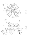
- a milling tool 40 which consists of a base body 8, which is formed by a wheel rim 43 and a wheel hub 27, which are integrally connected to one another by means of ribs 26.
- the peripheral surface of the wheel rim 43 is divided into two partial surfaces 10, 11, each of which has a different diameter 13, 14.
- 18 round-shaft chisels 4 are arranged as chisels distributed over the circumference of the partial surfaces 10, 11. Details of the milling tool 40 are explained in more detail below using the example of the milling tool 1.
- the milling tool 1 shown in FIGS. 3 and 4 consists of a base body 9 which is formed by a wheel rim 25 and a wheel hub 27 which are integrally connected to one another by means of ribs 26.
- the circumferential surface of the wheel rim 25 is divided into partial surfaces 10, 11, 12 of different diameters 13, 14, 15.
- the partial surfaces 10, 11, 12 are arranged such that the partial surface 10 with the largest diameter 13 adjoins the side edge 16 of the base body 9 and the partial surface 12 with the smallest diameter 15 adjoins the side edge 17 of the base body 9.
- the partial surface 11 with the average diameter 14 is located in the center of the base body 9.
- the peripheral surfaces of the base body 9 are thus formed in a step-like manner by the partial surfaces 10, 11, 12.
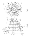
- FIGS. 5 and 6 This embodiment of a milling tool 2 is shown schematically in FIGS. 5 and 6.
- openings 20 are formed in the ribs 26 parallel to the central axis.
- the openings 20 can be designed as bores. Screw openings 21 can be guided through these openings 20, by means of which the disk wheel 22, the disk wheel 23 or both disk wheels 22, 23 can be connected to the base body 9.
- FIGS. 5 and 6 show an embodiment of a milling tool 2 in which a disk wheel 22 with a smaller diameter 29 than the diameter 15 is connected to the base body 9 by means of screw connections 21 which are guided through the openings 20.
- An additional connection of the base body 9 with a disk wheel 23, the partial surface 30 of which has a larger diameter 28 than the partial surface 10, is shown in FIGS. 5 and 6 by broken lines. Also with that 3 and 4 are located on the peripheral surfaces 10, 11, 12, 30, 31 as chisels 18.
- the milling tool 32 shown in FIGS. 7 and 8 consists of a base body 34 which is formed by a wheel rim 25 and a wheel hub 27 which are integrally connected to one another by means of ribs 26.
- the circumferential surface of the wheel rim 25 is divided into sub-surfaces 10, 11 of different diameters 13, 14.
- the partial surfaces 10, 11 are arranged such that the partial surfaces 11 with the smaller diameters 14 connect to the side edges 16 of the partial surface 10 with the largest diameter 13. It is also possible to form one of the partial surfaces 11 with a smaller diameter than the diameter 14. As a rule, however, it is expedient to provide the partial surfaces 11 with the same diameter 14 on both sides of the partial surface 10.
- the partial surface 10 with the largest diameter 13 is located in the middle of the base body 34.
- the partial surfaces 10, 11 thus design the peripheral surface of the base body 34 to rise in a step-like manner toward the center of the milling tool 32.
- the round-shaft chisels 4 already described above, which are welded to the base body 34 by means of their holding pieces 5, are arranged over the circumference as chisels 18.
- the wheel hub 27 is pushed onto a drive shaft of a construction machine and connected to it by means of the screw bolts 24 indicated in FIG. 8, as in the milling tool 1.
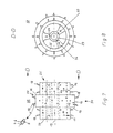
- FIGS. 9 and 10 This embodiment of a milling tool 33 is shown schematically in FIGS. 9 and 10.
- the openings 20 in the ribs 26 are formed by the base body 34 of the milling tool 33 parallel to its central axis 19. Through these openings 20 screw bolts 21 can be guided, by means of which both disc wheels 35, 36 can be connected to the base body 34.
- FIG. 9 The openings 20 in the ribs 26 are formed by the base body 34 of the milling tool 33 parallel to its central axis 19. Through these openings 20 screw bolts 21 can be guided, by means of which both disc wheels 35, 36 can be connected to the base body 34.
- FIGS. 9 and 10 show an embodiment of a milling tool 33 in which two disk wheels 35, 36 with a smaller but identical diameter 37, 38 compared to the diameter 14 of the partial surface 11 are connected to the base body 34 by means of screw bolts 21 which through the z. B. are designed as holes 20 openings. Also in the milling tool 33 according to FIGS. 9 and 10 there are preferably round shank chisels 4 on the partial surfaces 10, 11, 30, 31 as chisels.
Landscapes
- Engineering & Computer Science (AREA)
- Mining & Mineral Resources (AREA)
- Mechanical Engineering (AREA)
- Architecture (AREA)
- Civil Engineering (AREA)
- Structural Engineering (AREA)
- Road Repair (AREA)
Abstract
Description
Die Erfindung betrifft ein scheibenförmiges Fräswerkzeug mit an der radialen Umfangsfläche angeordneten Meißeln wie Rundschaftmeißeln od. dgl. zum Fräsen in dem Fahrbahnbelag aus Asphalt oder Beton einer Fahrbahndecke, das aus einem rotationssymmetrischen Grundkörper besteht, der in zwei oder mehr Teilflächen unterteilt ist.The invention relates to a disk-shaped milling tool with chisels arranged on the radial circumferential surface, such as round shank chisels or the like, for milling in the pavement from asphalt or concrete of a pavement surface, which consists of a rotationally symmetrical base body which is divided into two or more partial areas.
Zur Sanierung von Rissen, die sich längs der Fahrbahndecke gebildet haben und die bis zum Unterbau hinunter reichen können, ist es bekannt, die die Risse aufweisenden Fahrbahnschichten durch eine grabenartige Öffnung in der Fahrbahn zu entfernen. Die so gebildete Nut in der Fahrbahn wird dann wieder mit Asphalt verfüllt. Hierbei besteht der Nachteil, daß eine einwandfreie Verbindung mit den an die Nut angrenzenden Schichten der Fahrbahn häufig nicht erzielt werden kann, da an den Stoßflächen des eingebrachten Asphalts mit der alten Fahrbahn wegen nicht ausreichender mechanischer Verbindung Verwerfungen auftreten können, die einen ebenen Abschluß der Oberfläche des eingebrachten Asphalts mit der bestehenden Fahrbahnoberfläche verhindern. Um abgenutzte oder beschädigte Fahrbahnen aus Asphalt oder Beton zu überholen, ist es ferner erforderlich, vor Einbringen der neuen Fahrbahnschichten den alten abgenutzten oder beschädigten Fahrbahnbelag zu entfernen. Die betreffende Straße hierzu z. B. mit einem Hydraulikhammer aufgebrochen werden. Wenn nur ein halbseitiger Ausbau oder nur eine abschnittsweise Ausbesserung einer Fahrbahn gewünscht wird, ist es üblich, durch Schneiden od. dgl. den zu entfernenden Fahrbahnbelag von dem stehengebliebenen Fahrbahnbelag zu entfernen. Bei einem stumpfen Anschluß des neuen Fahrbahnbelages an den noch vorhandenen Fahrbahnbelag besteht stets die Gefahr, daß an den Stoßstellen durch Setzungen oder mechanische Einwirkungen Fahrbahnschäden oder Unregelmäßigkeiten auf der Fahrbahndecke auftreten. Um dies zu verhindern, ist bereits vorgeschlagen worden, die Fahrbahnstöße abgetreppt auszubilden. Dieses erfordert jedoch aufwendige Arbeiten zur Herstellung des abgetreppten Stoßabschnitts der Fahrbahn, da zwischen vertikalen Schnitten od. dgl. unterschiedlicher sich nach den Erfordernissen der jeweiligen Straßendecke richtender Tiefe befindliche Fahrbahnabschnitte durch besondere Arbeiten entfernt werden müssen.For the repair of cracks which have formed along the road surface and which can extend down to the substructure, it is known to remove the road surface layers having the cracks through a trench-like opening in the roadway. The groove formed in the roadway is then filled with asphalt again. The disadvantage here is that a perfect connection with the layers of the roadway adjacent to the groove can often not be achieved, since on the abutting surfaces of the asphalt introduced with the old roadway, warping can occur due to inadequate mechanical connection, which leads to a flat closure of the surface prevent the asphalt that has been brought in with the existing road surface. In order to overtake worn or damaged asphalt or concrete pavements, it is also necessary to remove the old worn or damaged pavement before applying the new pavement layers. The street in question z. B. be broken up with a hydraulic hammer. If only a half-sided removal or only a section-by-section repair of a carriageway is desired, it is common to remove the pavement to be removed from the pavement that has stopped by cutting or the like. If the new pavement is bluntly connected to the existing pavement, there is always the risk that the joint will cause damage to the pavement or irregularities on the pavement at the joints. In order to prevent this, it has already been proposed that the roadway joints be stepped. However, this requires extensive work to produce the stepped bump section of the roadway, since between vertical cuts or the like. Different roadway sections depending on the requirements of the respective road surface must be removed by special work.
Die Aufgabe der Erfindung besteht darin, ein Fräswerkzeug zu schaffen, mittels dem in einem Arbeitsgang eine zu überholende oder zu sanierende Fahrbahn so bearbeitet werden kann, daß das Material der neu eingebrachten Fahrbahn ohne Verwerfungen oder Setzungen mit der stehengebliebenen Fahrbahn eine feste Verbindung eingeht.The object of the invention is to provide a milling tool by means of which a roadway to be overhauled or renovated can be machined in one operation in such a way that the material of the newly introduced roadway enters into a firm connection with the remaining roadway without warping or settling.
Erfindungsgemäß erfolgt die Lösung der Aufgabe dadurch, daß die eine Teilfläche einen maximalen Durchmesser aufweist und die anderen Teilflächen ein- oder beidseitig zur ersten Teilfläche derart angeordnet sind, daß die Durchmesser dieser Teilflächen sich in axialer Richtung zur ersten Teilfläche abgestuft verringern, wobei auf der ersten Teilfläche sowie den weiteren Teilflächen über den Umfang verteilt die Meißel wie Rundschaftmeißel od. dgl. angeordnet sind.According to the invention, the object is achieved in that the one partial surface has a maximum diameter and the other partial surfaces are arranged on one or both sides of the first partial surface in such a way that the diameters of these partial surfaces decrease in the axial direction to the first partial surface, with the first Partial surface and the other partial surfaces distributed over the circumference of the chisels such as round shank chisels or the like are arranged.
Weitere Ausgestaltungen der Erfindung werden in den abhängigen Ansprüchen beschrieben und nachstehend näher anhand der in den Zeichnungen dargestellten Ausführungsbeispiele erläutert. Es zeigt
- Fig. 1 und 2 ein Fräswerkzeug in einer Seitenansicht, und Queransicht in Richtung A-A
- Fig. 3 bis 10 weitere Ausbildungen von Fräswerkzeugen in jeweils einer Seitenansicht, und einer Queransicht.
- 1 and 2 a milling tool in a side view, and transverse view in the direction AA
- Fig. 3 to 10 further designs of milling tools in a side view and a transverse view.
In Fig. 1 und 2 ist ein Fräswerkzeug 40 dargestellt, das aus einem Grundkörper 8 besteht, der durch einen Radkranz 43 und eine Radnabe 27 gebildet ist, die mittels Rippen 26 einstückig miteinander verbunden sind. Die Umfangsfläche des Radkranzes 43 ist in zwei Teilflächen 10, 11 unterteilt, die jeweils einen voneinander unterschiedlichen Durchmesser 13, 14 aufweisen. Über den Umfang der Teilflächen 10, 11 verteilt sind als Meißel 18 Rundschaftmeißel 4 angeordnet. Einzelheiten des Fräswerkzeugs 40 werden nachstehend am Beispiel des Fräswerkzeugs 1 näher erläutert.1 and 2, a
Das in Fig. 3 und 4 dargestellte Fräswerkzeug 1 besteht aus einem Grundkörper 9, der durch einen Radkranz 25 und eine Radnabe 27 gebildet ist, die mittels Rippen 26 einstückig miteinander verbunden sind. Die Umfangsfläche des Radkranzes 25 ist in Teilflächen 10, 11, 12 unterschiedlichen Durchmessers 13, 14, 15 unterteilt. Die Teilflächen 10, 11, 12 sind so angeordnet, daß die Teilfläche 10 mit dem größten Durchmesser 13 an die Seitenkante 16 des Grundkörpers 9 und die Teilfläche 12 mit dem kleinsten Durchmesser 15 an die Seitenkante 17 des Grundkörpers 9 anschließt. Die Teilfläche 11 mit dem mittleren Durchmesser 14 befindet sich in der Mitte des Grundkörpers 9. Durch die Teilflächen 10, 11, 12 ist somit die Umfangsfläche des Grundkörpers 9 treppenförmig ausgebildet. Auf den Teilflächen 10, 11, 12 sind über deren Umfang verteilt als Meißel 18 Rundschaftmeißel 4 angeordnet, die mittels ihrer Haltestücke 5 an dem Grundkörper 9 verschweißt sind. An jedem Haltestück 5 ist eine Metallbuchse 6 angeordnet, in der ein Hartmetalleinsatz 7 mit einer konischen Spitze drehbar gelagert ist. Zum Betrieb des Fräswerkzeugs 1 wird die Radnabe 27 auf eine Antriebswelle einer Baumaschine aufgeschoben und mittels Schraubbolzen 24 mit dieser verbunden. Die Schraubbolzen 24 sind in Fig. 4 ange deutet und können z. B. durch die Radnabe 27 geführt sein. Es ist aber auch möglich, die Schraubbolzen 24 durch Durchbrechungen in den Rippen 26 zu führen und mit einem an der Antriebswelle angeordneten Flansch zu verbinden.The
Bei Rotation des Fräswerkzeugs 1 um die Mittelachse 19 auf dem Fahrbahnbelag einer Fahrbahndecke wird in diesem ein Fahrbahnbelagabschnit derart aufgefräst, daß ein im Querschnitt abgetrepptes Profil entsteht. Diese Abtreppung ermöglicht eine bessere Verzahnung der neu einzubringenden Asphalt-oder Betonschicht mit dem noch stehengebliebenen Fahrbahnbelag.When the
Um mit einem Grundwerkzeug Abtreppungen mit weiteren Stufen ausführen zu können, ist es möglich, das Fräswerkzeug 1 durch ein zusätzliches Scheibenrad 23 oder zwei zusätzliche Scheibenräder 22, 23 zu verbreitern. Diese Ausführungsform eines Fräswerkzeugs 2 ist in Fig. 5 und 6 schematisch dargestellt. Durch den Grundkörper 9 des Fräswerkzeugs 1 sind parallel zu dessen Mittelachse 19 Durchbrechungen 20 in den Rippen 26 ausgebildet. Die Durchbrechungen 20 können als Bohrungen ausgebildet sein.Durch diese Durchbrechungen 20 können Schraubbolzen 21 geführt werden, mittels derer das Scheibenrad 22, das Scheibenrad 23 oder aber beide Scheibenräder 22, 23 mit dem Grundkörper 9 verbunden werden können. In Fig. 5 ist eine Ausführung eines Fräswerkzeugs 2 dargestellt, bei der ein Scheibenrad 22 mit einem gegenüber dem Durchmesser 15 geringeren Durchmesser 29 mit dem Grundkörper 9 mittels Schraubverbindungen 21 verbunden ist, die durch die Durchbrechungen 20 geführt sind. Eine zusätzliche Verbindung des Grundkörpers 9 mit einem Scheibenrad 23, dessen Teilfläche 30 einen gegenüber der Teilfläche 10 größeren Durchmesser 28 hat, ist in Fig. 5 und 6 durch Strichlinien dargestellt. Auch bei dem Fräswerkzeug 2 nach Fig. 3 und 4 befinden sich auf den Umfangsflächen 10, 11, 12, 30, 31 als Meißel 18 Rundschaftmeißel 4.In order to be able to carry out steps with further steps using a basic tool, it is possible to widen the
In den Fig. 7 bis 10 sind weitere Fräswerkzeuge 32, 33 dargestellt, die zur Sanierung von Rissen dienen, die sich längs der Fahrbahnmitte gebildet haben. Diese Risse können sich bis zum Unterbau erstrecken.7 to 10 show
Das in Fig. 7 und 8 dargestellte Fräswerkzeug 32 besteht aus einem Grundkörper 34, der durch einen Radkranz 25 und eine Radnabe 27 gebildet ist, die mittels Rippen 26 einstückig miteinander verbunden sind. Die Umfangsfläche des Radkranzes 25 ist in Teilflächen 10, 11 unterschiedlichen Durchmessers 13, 14 unterteilt. Die Teilflächen 10, 11 sind so angeordnet, daß an die Seitenkanten 16 der Teilfläche 10 mit dem größten Durchmesser 13 die Teilflächen 11 mit den kleineren Durchmessern 14 anschließen. Es ist auch möglich, eine der Teilflächen 11 mit gegenüber dem Durchmesser 14 kleinerem Durchmesser auszubilden. Im Regelfall ist es jedoch zweckmäßig, beidseitig der Teilfläche 10 die Teilflächen 11 mit gleichem Durchmesser 14 vorzusehen. Die Teilfläche 10 mit dem größten Durchmesser 13 befindet sich in der Mitte des Grundkörpers 34. Durch die Teilflächen 10, 11 ist somit die Umfangsfläche des Grundkörpers 34 zur Mitte des Fräswerkzeugs 32 hin treppenartig ansteigend ausgebildet. Auf den Teilflächen 10, 11 sind über den Umfang verteilt als Meißel 18 die bereits oben beschriebenen Rundschaftmeißel 4 angeordnet, die mittels ihrer Haltestücke 5 an dem Grundkörper 34 verschweißt sind. Zum Betrieb des Fräswerkzeugs 32 wird die Radnabe 27 auf eine Antriebswelle einer Baumaschine aufgeschoben und mittels der in Fig. 8 angedeuteten Schraubbolzen 24 mit dieser wie bei dem Fräswerkzeug 1 verbunden.The
Bei Rotation des Fräswerkzeuges 32 um die Mittelachse 19 auf einer Straßendecke wird in dieser ein Fahrbahnabschnitt derart aufgefräst, daß ein im Querschnitt symmetrisches, von beiden Seiten zur Fräsmitte hin abfallendes Treppenprofil entsteht. Rissbildungen werden bis hinunter zum Unterbau völlig ausgemerzt. Mit dem in der Mitte angeordneten Fräsrad 41 werden die Risse des Unterbaus mittig aufgefräst. Die beidseitig des Risses darüber liegenden Schichten wie. z. B. Binder- und Tragschicht werden mit den beidseitig zum Fräsrad 41 angeordneten kleineren Fräsrädern 42 aufgefräst. Nach Entfernen des Fräsputzes wird mit herkömmlichem Gußasphalt die Ausfräsung geschlossen und, falls erforderlich, lagenweise verdichtet. Die beim Einsatz des Fräswerkzeugs 32 erzielten Abtreppungen ermöglichen eine bessere Verzahnung des neu einzubringenden Gußasphalts mit der stehengebliebenen Fahrbahndecke bzw. dem stehengebliebenen Fahrbahnbelag.When the
Um mit einem Grundwerkzeug weitere symmetrische Abtreppungen ausfräsen zu können, ist es möglich, das Fräswerkzeug 32 durch zusätzliche Scheibenräder 35, 36 symmetrisch zu verbreitern, die wie die Scheibenräder 22, 23 als Fräsräder ausgebildet sind. Diese Ausführungsform eines Fräswerkzeugs 33 ist in Fig. 9 und 10 schematisch dargestellt. Durch den Grundkörper 34 des Fräswerkzeugs 33 sind parallel zu dessen Mittelachse 19 die Durchbrechungen 20 in den Rippen 26 ausgebildet. Durch diese Durchbrechungen 20 können Schraubbolzen 21 geführt werden, mittels derer beide Scheibenräder 35, 36 mit dem Grundkörper 34 verbunden werden können. In Fig. 9 ist eine Ausführung eines Fräswerkzeugs 33 dargestellt, bei der zwei Scheibenräder 35, 36 mit einem gegenüber dem Durchmesser 14 der Teilfläche 11 geringeren aber gleichen Durchmesser 37, 38 mit dem Grundkörper 34 mittels Schraubbolzen 21 verbunden sind, die durch die z. B. als Bohrungen ausgebildeten Durchbrechungen 20 geführt sind. Auch bei dem Fräswerkzeug 33 nach Fig. 9 und 10 befinden sich umfangsseitig auf den Teilflächen 10, 11, 30, 31 als Meißel vorzugsweise Rundschaftmeißel 4.In order to be able to mill out further symmetrical steps with a basic tool, it is possible to broaden the
Claims (11)
Applications Claiming Priority (2)
| Application Number | Priority Date | Filing Date | Title |
|---|---|---|---|
| DE19863616060 DE3616060A1 (en) | 1986-05-13 | 1986-05-13 | DISC SHAPED MILLING TOOL |
| DE3616060 | 1986-05-13 |
Publications (2)
| Publication Number | Publication Date |
|---|---|
| EP0245810A2 true EP0245810A2 (en) | 1987-11-19 |
| EP0245810A3 EP0245810A3 (en) | 1988-08-17 |
Family
ID=6300708
Family Applications (1)
| Application Number | Title | Priority Date | Filing Date |
|---|---|---|---|
| EP87106775A Withdrawn EP0245810A3 (en) | 1986-05-13 | 1987-05-10 | Disk-shaped milling tool |
Country Status (2)
| Country | Link |
|---|---|
| EP (1) | EP0245810A3 (en) |
| DE (1) | DE3616060A1 (en) |
Cited By (7)
| Publication number | Priority date | Publication date | Assignee | Title |
|---|---|---|---|---|
| WO1989009307A1 (en) * | 1988-03-31 | 1989-10-05 | Muehlstaedter Alexander | Process and device for making manholes in roads |
| FR2706497A1 (en) * | 1993-06-14 | 1994-12-23 | Gerland Routes | Method for repairing a roadway |
| GB2290050A (en) * | 1994-06-11 | 1995-12-13 | Marcrist Ind Ltd | Cutting blades |
| WO2000070149A1 (en) * | 1999-05-18 | 2000-11-23 | Anthony Richard Schibeci | Cutting apparatus for removal of road surfaces and other mining and earth removal operations |
| US6547484B2 (en) * | 2001-02-14 | 2003-04-15 | Dustrol, Inc. | Apparatus for cutting rumble strips in a road surface |
| USRE40505E1 (en) | 2001-02-14 | 2008-09-16 | Dustrol, Inc. | Apparatus for cutting rumble strips in a road surface |
| US10323364B2 (en) * | 2017-09-15 | 2019-06-18 | Coneqtec Corp. | Asphalt milling cutter arrangements |
Families Citing this family (4)
| Publication number | Priority date | Publication date | Assignee | Title |
|---|---|---|---|---|
| DE3807787A1 (en) * | 1988-03-09 | 1989-10-05 | Reinhard Wirtgen | Method and device for repairing longitudinal seams or longitudinal cracks in roadway pavings |
| DE3926942A1 (en) * | 1989-08-14 | 1991-02-21 | Werner Blume | Roughening surface of floor or wall - involves tool consisting of disc with sharp-edged projections |
| DE102005022336A1 (en) * | 2005-05-13 | 2006-11-16 | SFH Maschinen- und Anlagenservice für Betonsteinindustrie GmbH | Polishing tool for masonry surfaces has a rotating disc with polishing tools in two rings in two height settings |
| DE102014015584B4 (en) * | 2014-10-21 | 2018-10-25 | Bomag Gmbh | Milling roller and ground milling machine with such a milling drum |
Citations (4)
| Publication number | Priority date | Publication date | Assignee | Title |
|---|---|---|---|---|
| US2349949A (en) * | 1942-12-14 | 1944-05-30 | Far Lin Inc | Apparatus for cutting channels in road surfaces |
| DE2719879A1 (en) * | 1976-04-30 | 1977-11-10 | Amerace Corp | SNOWPLOW RESISTANT ROAD MARKING AND METHOD AND DEVICE FOR SETTING THE SAME |
| DE2412252B2 (en) * | 1974-03-14 | 1978-03-09 | Reinhard 5461 Windhagen Wirtgen | Process for repairing a road surface course and machine for carrying out the process |
| DE8612998U1 (en) * | 1986-05-13 | 1986-09-18 | Rapa Baudienst GmbH, 2102 Hamburg | Disc-shaped milling tool |
Family Cites Families (2)
| Publication number | Priority date | Publication date | Assignee | Title |
|---|---|---|---|---|
| DE2517669C2 (en) * | 1975-04-22 | 1985-06-27 | Wengeler & Kalthoff, 4320 Hattingen | Milling cutting machine for cutting recesses in natural or artificial stone |
| DE2816176C2 (en) * | 1978-04-14 | 1985-06-05 | Marks Gmbh & Co Kg, 4350 Recklinghausen | Milling shaft bearing for a milling drum for a road milling machine |
-
1986
- 1986-05-13 DE DE19863616060 patent/DE3616060A1/en not_active Withdrawn
-
1987
- 1987-05-10 EP EP87106775A patent/EP0245810A3/en not_active Withdrawn
Patent Citations (4)
| Publication number | Priority date | Publication date | Assignee | Title |
|---|---|---|---|---|
| US2349949A (en) * | 1942-12-14 | 1944-05-30 | Far Lin Inc | Apparatus for cutting channels in road surfaces |
| DE2412252B2 (en) * | 1974-03-14 | 1978-03-09 | Reinhard 5461 Windhagen Wirtgen | Process for repairing a road surface course and machine for carrying out the process |
| DE2719879A1 (en) * | 1976-04-30 | 1977-11-10 | Amerace Corp | SNOWPLOW RESISTANT ROAD MARKING AND METHOD AND DEVICE FOR SETTING THE SAME |
| DE8612998U1 (en) * | 1986-05-13 | 1986-09-18 | Rapa Baudienst GmbH, 2102 Hamburg | Disc-shaped milling tool |
Cited By (8)
| Publication number | Priority date | Publication date | Assignee | Title |
|---|---|---|---|---|
| WO1989009307A1 (en) * | 1988-03-31 | 1989-10-05 | Muehlstaedter Alexander | Process and device for making manholes in roads |
| FR2706497A1 (en) * | 1993-06-14 | 1994-12-23 | Gerland Routes | Method for repairing a roadway |
| GB2290050A (en) * | 1994-06-11 | 1995-12-13 | Marcrist Ind Ltd | Cutting blades |
| WO2000070149A1 (en) * | 1999-05-18 | 2000-11-23 | Anthony Richard Schibeci | Cutting apparatus for removal of road surfaces and other mining and earth removal operations |
| US6779850B1 (en) | 1999-05-18 | 2004-08-24 | Anthony Richard Schibeci Watsonia | Cutting apparatus having means for shielding cutting tool holders |
| US6547484B2 (en) * | 2001-02-14 | 2003-04-15 | Dustrol, Inc. | Apparatus for cutting rumble strips in a road surface |
| USRE40505E1 (en) | 2001-02-14 | 2008-09-16 | Dustrol, Inc. | Apparatus for cutting rumble strips in a road surface |
| US10323364B2 (en) * | 2017-09-15 | 2019-06-18 | Coneqtec Corp. | Asphalt milling cutter arrangements |
Also Published As
| Publication number | Publication date |
|---|---|
| DE3616060A1 (en) | 1987-11-19 |
| EP0245810A3 (en) | 1988-08-17 |
Similar Documents
| Publication | Publication Date | Title |
|---|---|---|
| EP0245810A2 (en) | Disk-shaped milling tool | |
| AT410951B (en) | METHOD FOR REPROFILING AT LEAST THE TRAVEL MIRROR OF A RAIL AND DEVICE THEREFOR | |
| EP1840268A1 (en) | Mill cylinder for construction machinery, construction machinery and a drive unit for a mill cylinder | |
| EP1301662A1 (en) | Method for grinding a rail and device for carrying out said method | |
| EP0185850A2 (en) | Underfloor wheelset lathe for reprofiling the contours of wheel rims of railway wheelsets | |
| EP0633107B1 (en) | Apparatus for finishing concrete pipes | |
| EP0058746A2 (en) | Device for working the steps of a stone stair-case | |
| EP1142673A2 (en) | Grinding flap and Grinding disc having a plurality of such flaps | |
| DE8612998U1 (en) | Disc-shaped milling tool | |
| EP1207010B1 (en) | Grinding machine | |
| DE19917478B4 (en) | Basic body of a grinding head set up for use in a device intended for grinding a rail connection | |
| DE2412252C3 (en) | Process for repairing a road surface course and machine for carrying out the process | |
| DE3807787C2 (en) | ||
| DE3641890C2 (en) | ||
| DE3621251C2 (en) | ||
| DE3641853C2 (en) | ||
| EP4012105B1 (en) | Method for mounting a cutting wheel of a trench wall cutter | |
| DE202023103643U1 (en) | Joint chisel for elastic joints in hot asphalt | |
| EP1023942B1 (en) | Shredding device with at least one rotary shaft | |
| DE10056130A1 (en) | Manhole cover supported by ground-frame and end-frame uses removable height-adjustable supports on ground-frame to carry removable frame edged to support manhole cover and edged below for manhole jacking. | |
| CH587386A5 (en) | ||
| DE102021111018A1 (en) | puller | |
| EP1362954A1 (en) | Milling head for a construction machine | |
| DE102021111016A1 (en) | puller | |
| DE102022125063A1 (en) | Processing unit for a self-propelled device for edge processing of already installed curbs, self-propelled device with such and edge processing methods |
Legal Events
| Date | Code | Title | Description |
|---|---|---|---|
| PUAI | Public reference made under article 153(3) epc to a published international application that has entered the european phase |
Free format text: ORIGINAL CODE: 0009012 |
|
| AK | Designated contracting states |
Kind code of ref document: A2 Designated state(s): AT BE CH DE ES FR IT LI NL |
|
| PUAL | Search report despatched |
Free format text: ORIGINAL CODE: 0009013 |
|
| AK | Designated contracting states |
Kind code of ref document: A3 Designated state(s): AT BE CH DE ES FR IT LI NL |
|
| RHK1 | Main classification (correction) |
Ipc: E01C 23/08 |
|
| STAA | Information on the status of an ep patent application or granted ep patent |
Free format text: STATUS: THE APPLICATION IS DEEMED TO BE WITHDRAWN |
|
| 18D | Application deemed to be withdrawn |
Effective date: 19890419 |
|
| RIN1 | Information on inventor provided before grant (corrected) |
Inventor name: GOLDBERG, JUERGEN |