EP0245749B1 - Permanenterregter Gleichstrommotor - Google Patents
Permanenterregter Gleichstrommotor Download PDFInfo
- Publication number
- EP0245749B1 EP0245749B1 EP19870106453 EP87106453A EP0245749B1 EP 0245749 B1 EP0245749 B1 EP 0245749B1 EP 19870106453 EP19870106453 EP 19870106453 EP 87106453 A EP87106453 A EP 87106453A EP 0245749 B1 EP0245749 B1 EP 0245749B1
- Authority
- EP
- European Patent Office
- Prior art keywords
- direct
- carrier ring
- current motor
- carbon brushes
- ring
- Prior art date
- Legal status (The legal status is an assumption and is not a legal conclusion. Google has not performed a legal analysis and makes no representation as to the accuracy of the status listed.)
- Expired - Lifetime
Links
- 238000004804 winding Methods 0.000 claims description 32
- OKTJSMMVPCPJKN-UHFFFAOYSA-N Carbon Chemical compound [C] OKTJSMMVPCPJKN-UHFFFAOYSA-N 0.000 claims description 31
- 229910052799 carbon Inorganic materials 0.000 claims description 31
- RYGMFSIKBFXOCR-UHFFFAOYSA-N Copper Chemical compound [Cu] RYGMFSIKBFXOCR-UHFFFAOYSA-N 0.000 claims description 5
- 229910052802 copper Inorganic materials 0.000 claims description 5
- 239000010949 copper Substances 0.000 claims description 5
- 239000007787 solid Substances 0.000 claims description 5
- XEEYBQQBJWHFJM-UHFFFAOYSA-N Iron Chemical group [Fe] XEEYBQQBJWHFJM-UHFFFAOYSA-N 0.000 claims description 3
- 239000000853 adhesive Substances 0.000 claims 1
- 230000001070 adhesive effect Effects 0.000 claims 1
- 229910000679 solder Inorganic materials 0.000 description 3
- 229910000831 Steel Inorganic materials 0.000 description 1
- 238000010276 construction Methods 0.000 description 1
- 230000006735 deficit Effects 0.000 description 1
- 230000005670 electromagnetic radiation Effects 0.000 description 1
- 238000010438 heat treatment Methods 0.000 description 1
- 229910052742 iron Inorganic materials 0.000 description 1
- 238000010030 laminating Methods 0.000 description 1
- 238000003754 machining Methods 0.000 description 1
- 238000004519 manufacturing process Methods 0.000 description 1
- 239000002184 metal Substances 0.000 description 1
- 229910052751 metal Inorganic materials 0.000 description 1
- 238000003801 milling Methods 0.000 description 1
- 230000010349 pulsation Effects 0.000 description 1
- 230000005855 radiation Effects 0.000 description 1
- 230000001105 regulatory effect Effects 0.000 description 1
- 239000010959 steel Substances 0.000 description 1
Images


Classifications
-
- H—ELECTRICITY
- H02—GENERATION; CONVERSION OR DISTRIBUTION OF ELECTRIC POWER
- H02K—DYNAMO-ELECTRIC MACHINES
- H02K23/00—DC commutator motors or generators having mechanical commutator; Universal AC/DC commutator motors
- H02K23/54—Disc armature motors or generators
-
- H—ELECTRICITY
- H02—GENERATION; CONVERSION OR DISTRIBUTION OF ELECTRIC POWER
- H02K—DYNAMO-ELECTRIC MACHINES
- H02K23/00—DC commutator motors or generators having mechanical commutator; Universal AC/DC commutator motors
- H02K23/02—DC commutator motors or generators having mechanical commutator; Universal AC/DC commutator motors characterised by arrangement for exciting
- H02K23/04—DC commutator motors or generators having mechanical commutator; Universal AC/DC commutator motors characterised by arrangement for exciting having permanent magnet excitation
Definitions
- the invention relates to a positive-locking, permanently excited DC motor according to the preamble of claim 1.
- Such a permanently excited DC motor is known from DE-A1-32 13 172.
- a positive-locking, decoupled, electromotive rotary drive for gun and armored turrets is described, the rotary drive being a torque ring motor, the stator of which is flanged to the fixed lower part and the rotor of which is flanged to the rotatable upper part.
- the torque ring motor is a permanent magnet DC motor with a shunt characteristic.
- the armature winding is arranged in a ring shape in the form of radial lamellae in the form of a rod. Commutation takes place directly on the anchor rods. This eliminates the special commutator known from the conventional DC motor.
- the field is built up using permanent magnets, which are arranged both above and below the rotor ring.
- the magnetic yoke takes place via steel carrier rings.
- the invention is based on the object of specifying a positive-locking, permanently excited DC motor of the type mentioned, which is universally suitable for the direct drive of large rotating devices, such as radar systems, rotating cranes, etc. in the range of low rotational frequencies, can develop very high torques and a very has high mechanical stability.
- the permanently excited direct current motor can be used universally as an actuator or direct drive without a gear in the range from low to very low rotational frequencies.
- the drive is almost completely wear-free, smooth and with high dynamics. The maximum torque can also be delivered when the vehicle is at a standstill.
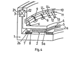
- Fig. 4 shows a second embodiment of the permanent magnet DC motor.
- the main components of the motor are a coil carrier ring 1 with DC winding 2 arranged perpendicular to the plane of rotation, a rotary bearing 3 and a magnet carrier ring 4 arranged perpendicular to the plane of rotation with a large number of permanent magnets 5 and a large number of brush holders 6 with carbon brushes 7 guided therein.
- the coil carrier ring 1 is also not laminated in the area of the winding 2, but rather is of solid construction.
- the coil carrier ring 1 is provided with grooves and teeth.
- the winding 2 consists of solid copper rods which are insulated into the slots in the top and bottom layers.
- the individual copper bars are soldered to each other at the ends of the winding heads 2a, 2b.
- the permanent magnets 5 are located on the magnet carrier ring 4 opposite the winding 2, separated by a narrow magnetic air gap 5a.
- the permanent magnets 5 are preferably glued into millings or bores of the magnet carrier ring 4, namely that a north pole alternates with a south pole along the circumference.
- 60 pole pairs i.e. 60 north poles and 60 south poles can be provided along the circumference of the magnet carrier ring 4.
- the winding head 2b At the level of the winding head 2b, 4 brush holders 6 are provided on the magnetic carrier ring, specifically a brush holder 6 can be located between two poles, ie with 60 pole pairs up to 120 brush holders 6 can be present.
- the number of carbon brushes 7 does not have to match the number of poles. If the carbon brushes are reduced to half or even less, economic advantages may be achieved.
- the winding head 2b has a machining process to form a commutator surface 8. As a result of the current transfer directly to the winding head 2b, there is a uniform heating in comparison to the conventional commutator machine, even when generating torque in the continuous standstill, since all the carbon brushes 7 current at the same time are leaders.
- the carbon brushes 7 are supplied with power via strands 9 which, on the one hand, are pressed into the carbon brushes 7 and, on the other hand, are connected to collecting rings 10, 11, preferably brazed.
- a carbon brush 7 is alternately connected along the circumference to the collecting line 10 and the adjacent carbon brush is connected to the collecting line 11.
- the two collector rings 10, 11 are inserted in insulated fashion in the magnet carrier ring 4.
- the power supply to the collecting rings 10 and 11 takes place in each case via at least two connecting cables 12 and 13.
- 4 such connecting cables 12, 13 are at equal (or appropriate) intervals along the circumference of the Collection rings 10, 11 attached.
- the collecting ring 10 is applied, for example, with positive voltage U + and the collecting ring 11 with negative voltage U-. Reversing the direction of rotation of the rotor results from swapping.
- the arrangement of the collecting rings 10, 11 is based in principle on the arrangement of the carbon brushes 7.
- the collecting rings can be arranged with two poles all round or interrupted, two-pole sectorally symmetrical or asymmetrical, single-pole in each case at half the circumference or single-pole sectorally symmetrical or asymmetrical.
- the motor feed should be placed in such a way that the radiation of the magnetic field caused by the feed lines and the collecting rings is as small as possible.
- FIG. 2 shows a view of the magnetic carrier ring 4 of the direct current motor.
- Four permanent magnets 5 can be seen, the north poles with N and the south poles with S. Because of the pole slope, there is advantageously no torque pulsation even at the lowest speeds and no preferred rotor positions are formed. Instead of the pole slope, a slot slope can also be provided.
- the brush holders 6 with the carbon brushes are located above the permanent magnets 5 in the region of the indicated commutator surface 8 of the winding head 2b.
- the inclination of the brush holder 6 is aligned with the copper bars of the winding in the area of the commutator surface 8 on the winding head 2b. It is indicated in each case whether the carbon brushes 7 are supplied with positive voltage U + or with negative voltage U-.
- Fig. 3 is a view of the coil carrier ring 1 of the DC motor is shown.
- the coil carrier ring 1 is provided with grooves 14 and teeth 15.
- the winding 2 is designed as a shaft winding with top and bottom bars made of copper.
- the individual rods are brazed to each other at the ends of the winding heads 2a and 2n.
- the solder joints are designated 16.
- the rod 17 is, for example, an upper rod, i.e. the rod takes the top layer in the groove 14.
- the upper rod 17 is soldered to the lower rod 18 at the end of the winding head 2b and to the lower rod 19 at the end of the winding head 2a.
- the sub-rods 18, 19 each take the documents in the grooves 14.
- the spatial distance between the solder joint 16 of the stems 17, 18 and the solder joint 16 of the stems 17, 19 is denoted by A.
- This distance A also corresponds to the spatial distance A between two carbon brushes 7 or also the spatial distance between two permanent magnets 5 of the magnet carrier ring 4.
- three carbon brushes 7 and two permanent magnets 5 are outlined in the representation of the wound coil carrier ring 1.
- Insulating pieces 20 are inserted between the individual bars of the winding 2. As already mentioned, the bars in the area of the winding head 2b are slightly milled or turned in order to obtain a flat commutator surface 8 for the carbon brushes 7.
- the coil carrier ring 1 and the magnet carrier ring 4 are not arranged vertically, but horizontally to the plane of rotation.
- the winding 2 with the two winding heads 2a, 2n and the commutator surface 8, the permanent magnets 5, the magnetic air gap 5a, the brush holders 6 with carbon brushes 7, the strands 9, the collecting rings 10, 11, the connecting cables 12, 13 and to recognize the pivot bearing 3.
- the coil carrier 1 of the DC motor can be used either as a stator or as a rotor.
- the magnet carrier ring 4 functions as a rotor.
- the magnet carrier ring 4 is then connected to the rotatable part of the device to be driven (e.g. via screw connections 22), while the coil carrier ring 1 is attached to the fixed part of the device to be driven (e.g. also via screw connections 21).
- the magnet carrier ring 4 functions as a stator.
- the magnet carrier ring 4 is then connected to the fixed part and the coil carrier ring 1 to the rotatable part of the device to be driven.
- the coil carrier ring 1 and 4 each show as an example that the coil carrier ring 1 is designed as an outer ring and the magnet carrier ring 4 as an inner ring of the direct current motor.
- the magnetic carrier ring 4 it is also possible to use the magnetic carrier ring 4 as an outer ring and to form the coil support ring 1 as an inner ring.
- the coil carrier ring 1 and the magnet carrier ring 4 can each act optionally as a rotor or stator.
- the permanent magnet DC motor can be used as a highly dynamic control drive.
- the reversal of the direction of rotation can never be up to approximately 1000 per second.
- the polarity of the collector rings 10, 11 changes to 1000 times per second.
- the permanent-magnet DC motor described is preferably suitable for the direct drive of radar systems, satellite tracking antennas, rotating cranes, machine tool turntables, computer tomographs and armored towers. Speeds in the range from 10 rpm to 1/1000 rpm are preferably achievable. The maximum torque is applied even at the lowest speeds or at a standstill.
- the DC motor is preferably supplied via a regulated converter.
Landscapes
- Engineering & Computer Science (AREA)
- Power Engineering (AREA)
- Dc Machiner (AREA)
Description
- Die Erfindung bezieht sich auf einen formschlußlosen, permanenterregten Gleichstrommotor gemäß dem Oberbegriff des Anspruchs 1.
- Ein solcher permanenterregter Gleichstrommotor ist aus der DE-A1-32 13 172 bekannt. Dort wird ein formschlußloser, entkoppelter, elektromotorischer Drehantrieb für Geschütz-und Panzertürme beschrieben, wobei der Drehantrieb ein Torque-Ring-Motor ist, dessen Stator am feststehenden Unterteil und dessen Rotor am drehbaren Oberteil angeflanscht ist. Der Torque-Ring-Motor ist im Prinzip ein permanenterregter Gleichstrommotor mit Nebenschluß-Charakteristik. Die Ankerwicklung ist in Form von strahlenförmigen Lamellen in Stabform ringartig angeordnet. Die Kommutierung erfolgt direkt auf den Ankerstäben. Damit entfällt der besondere, vom Gleichstrommotor üblicher Bauart her bekannte Kommutator. Der Feldaufbau erfolgt mittels Dauermagenten, die sowohl über als auch unter dem Läuferring angeordnet sind. Der Magnet-Rückschluß erfolgt über Stahlträgerringe.
- Der Erfindung liegt davon ausgehend die Aufgabe zugrunde, einen formschlußlosen, permanenterregten Gleichstrommotor der eingangs genannten Art anzugeben, der universell zum Direktantrieb großer drehbarer Einrichtungen, wie Radaranlagen, Drehkräne usw. im Bereich kleiner Drehfrequenzen geeignet ist, dabei sehr hohe Drehmomente entwickeln kann und eine sehr hohe mechanische Stabilität aufweist.
- Diese Aufgabe wird in Verbindung mit den Merkmalen des Oberbegriffs erfindungsgemäß durch die im Kennzeichen des Anspruchs 1 angegebenen Merkmale gelöst.
- Vorteilhafte Ausgestaltungen der Erfindung sind in den Unteransprüchen gekennzeichnet.
- Aus der GB-A-1 581 350 ist ein Gleichstrommotor für kleine Drehfrequenzen bekannt, wobei Gehäuse und Spulenring, der aus einem Sintermetall besteht, allerdings aus zwei Teilen aufgebaut sind, so daß dieser Stand der Technik keinerlei Anregung zu der erfindungsgemäßen Ausbildung geben konnte.
- Die mit der Erfindung erzielbaren Vorteile bestehen insbesondere darin, daß der permanenterregte Gleichstrommotor universell als Stellantrieb bzw. Direktantrieb ohne Getriebe im Bereich kleiner bis kleinster Drehfrequenzen einsetzbar ist. Durch Fortfall des bei Einsatz eines Getriebes nicht auszuschließenden Flankenspiels wird eine äußerst exakte Positionierung möglich. Im Vergleich zum Gleichstrommotor nach der DE-A1-32 13 172 ergibt sich ein geringerer Luftspalt, eine höhere mechanische Steifigkeit und eine wirtschaftlichere Bauart, insbesondere sind weniger Dauermagnete notwendig. Der Antrieb erfolgt fast völlig verschleißfrei, reibungslos und mit hoher Dynamik. Auch im Stillstand kann das maximale Moment abgegeben werden.
- Fig. 2 eine Ansicht auf den Magnetträgerring des Gleichstrommotors,
- Fig. 3 eine Ansicht auf den Spulenträgerring des Gleichstrommotors,
- Fig. 4 eine zweite Ausführungsvariante des Permanenterregten Gleichstrommotors.
- In Fig. 1 ist eine erste Ausführungsvariante des permanenterregten Gleichstrommotors dargestellt. Der Motor weist als Hauptbauteile einen senkrecht zur Rotationsebene angeordneten Spulenträgerring 1 mit Gleichstromwicklung 2, ein Drehlager 3 und einen senkrecht zur Rotationsebene angeordneten Magnetträgerring 4 mit einer Vielzahl von Dauermagneten 5 und einer Vielzahl von Bürstenhaltern 6 mit darin geführten Kohlebürsten 7 auf. Der Spulenträgerring 1 ist auch im Bereich der Wicklung 2 nicht lamelliert, sondern massiv ausgeführt.
- Der Verzicht auf eine Lamellierung des Blechpaketes ist möglich, da der Gleichstrommotor im Bereich kleiner und kleinster Drehzahlen betrieben werden soll und dementsprechend nur kleine Ummagnetisierungsfrequenzen auftreten. Die Vorteile der massiven Ausführung des Spulenträgerrings 1 bestehen einmal darin, daß die Bearbeitung einfacher und die Herstellung preisgünstiger wird, vor allem jedoch darin, daß der Spulenträgerring 1 mechanisch sehr stabil wird. Der Nachteil der höheren Eisenverluste ist aufgrund der auftretenden kleinen Frequenzen vernachlässigbar.
- Zur Einlage der Wicklung 2 ist der Spulenträgerring 1 mit Nuten und Zähnen versehen. Die Wicklung 2 besteht aus massiven Kupferstäben, die in Unter- und Oberlage isoliert in die Nuten eingelegt sind. Jeweils an den Enden der Wickelköpfe 2a, 2b sind die einzelnen Kupferstäbe miteinander verlötet.
- Die Dauermagnete 5 befinden sich auf dem Magnetträgerring 4 gegenüber der Wicklung 2, getrennt durch einen schmalen magnetischen Luftspalt 5a. Die Dauermagnete 5 sind vorzugsweise in Einfräsungen oder Bohrungen des Magnetträgerrings 4 eingeklebt und zwar folgt längs des Umfanges jeweils abwechselnd ein Nordpol auf einen Südpol. Es können z.B. 60 Polpaare, d.h. 60 Nordpole und 60 Südpole längs des Umfanges des Magnetträgerringes 4 vorgesehen sein.
- In Höhe des Wickelkopfes 2b sind auf dem Magnetträgerring 4 Bürstenhalter 6 vorgesehen, und zwar kann zwischen zwei Polen je ein Bürstenhalter 6 liegen, d.h. bei 60 Polpaaren können bis zu 120 Bürstenhalter 6 vorhanden sein. Die Anzahl der Kohlebürsten 7 muß jedoch nicht mit der Anzahl der Pole übereinstimmen. Bei Reduzierung der Kohlebürsten auf den halben bzw. auf einen noch kleineren Wert sind gegebenenfalls wirtschaftliche Vorteile zu erzielen. Zur Kontaktierung mit den Kohlebürsten 7 weist der Wickelkopf 2b eine Bearbeitung zur Bildung einer Kommutatorfläche 8 auf. Infolge der Stromübertragung direkt auf den Wickelkopf 2b ergibt sich eine gleichmäßige Erwärmung im Vergleich zur konventionellen Kommutator-Maschine, selbst bei einer Momenterzeugung im dauernden Stillstand, da alle Kohlebürsten 7 gleichzeitig stromführend sind.
- Die Stromversorgung der Kohlebürsten 7 erfolgt über Litzen 9, die einerseits in die Kohlebürsten 7 eingepreßt sind, andererseits mit Sammelringen 10, 11 verbunden, vorzugsweise hartverlötet sind. Längs des Umfanges ist abwechselnd eine Kohlenürste 7 mit der Sammelleitung 10 und die benachnarte Kohlebürste mit der Sammelleitung 11 verbunden. Daneben ist es auch möglich, die Kohlebürsten 7 jeweils gruppenweise mit je einem Sammelring zu verbinden. Prinzipiell ist es ferner möglich, die Kohlebürsten 7 lediglich auf Teilen längs des Umfanges des Magnetträgerringges 4 anzuordnen, was Raumvorteile bringen kann. Bei der Anordnung der Kohlebürsten ist vor allem zu beachten, daß die elektromagnetische Abstrahlung und Beeinträchtigung benachbarter Geräteeinbauten vermieden oder zumindest minimiert wird. Die beiden Sammelringe 10, 11 sind isoliert in Einfräsungen des Magnetträgerrings 4 eingelegt. Die Stromversorgung der Sammelringe 10 bzw. 11 erfolgt jeweils über mindestens zwei Anschlußkabel 12 bzw. 13. Um den Querschnitt der Sammelringe möglichst gering zu halten, sind beispielsweise jeweils 4 derartiger Anschlußkabel 12, 13 in gleichmäßigen (bzw. zweckmäßigen) Abständen längs des Umfanges der Sammelringe 10, 11 angebracht. Der Sammelring 10 wird dabei beispielsweise mit positiver Spannung U+ und der Sammelring 11 mit negativer Spannung U- beaufschlagt. Durch Vertauschen erfolgt eine Drehrichtungsumkehr des Rotors. Die Anordnung der Sammelringe 10, 11 richtet sich prinzipiell nach der Anordnung der Kohlebürsten 7. Die Sammelringe können zweipolig rundum durchgängig oder unterbrochen, zweipolig sektoral symmetrisch oder unsymmetrisch, einpolig jeweils am halben Umfang odereinpolig sektoral spiegelsymmetrisch oder unsymmetrisch angeordnet sein. Die Einspeisung des Motors soll so gelegt werden, daß die Abstrahlung des durch die Zuleitungen und die Sammelringe verursachten Magnetfeldes möglichst klein wird.
- In Fig. 2 ist eine Ansicht auf den Magnetträgerring 4 des Gleichstrommotors dargestellt. Es sind vier Dauermagnete 5 zu erkennen, wobei die Nordpole mit N und die Südpole mit S bezeichnet sind. Aufgrund der Polschrägung ergeben sich vorteilhaft auch bei kleinsten Drehzahlen keine Momentenpulsationen und es bilden sich keine bevorzugten Rotorstellungen aus. Anstelle der Polschrägung kann auch eine Nutschrägung vorgesehen sein.
- Oberhalb der Dauermagnete 5 im Bereich der angedeuteten Kommutatorfläche 8 des Wickelkopfes 2b befinden sich die Bürstenhalter 6 mit den Kohlebürsten. Die Schrägstellung der Bürstenhalter 6 ist dabei nach den Kupferstäben der Wicklung im Bereich der Kommutatorfläche 8 auf dem Wickelkopf 2b ausgerichtet. Es ist jeweils bezeichnet, ob die Kohlebürsten 7 mit positiver Spannung U+ oder mit negativer Spannung U-beaufschlagt sind.
- In Fig. 3 ist eine Ansicht auf den Spulenträgerring 1 des Gleichstrommotors dargestellt. Im Bereich der Wicklung 2 ist der Spulenträgerring 1 mit Nuten 14 und Zähnen 15 versehen. Die Wicklung 2 ist als Wellenwicklung mit Ober- und Unterstäben aus Kupfer ausgeführt. Die einzelnen Stäbe sind jeweils an den Enden der Wickelköpfe 2a und 2n miteinander hartverlötet. Die Lötstellen sind mit 16 bezeichnet. Beim Stab 17 handelt es sich beispielsweise um einen Oberstab, d.h. der Stab nimmt die Oberlage in der Nut 14 ein. Der Oberstan 17 ist am Ende des Wickelkopfes 2b mit dem Unterstab 18 und am Ende des Wickelkopfes 2a mit dem Unterstab 19 verlötet. Die Unterstäbe 18, 19 nehmen jeweils die Unterlagen in den Nuten 14 ein. Der räumliche Abstand zwischen der Lötstelle 16 der Stäne 17, 18 und der Lötstelle 16 der Stäne 17, 19 ist mit A bezeichnet. Dieser Abstand A entspricht ebenfalls dem räumlichen Abstand A zwischen zwei Kohlebürsten 7 bzw. ebenfalls dem räumlichen Abstand zwischen zwei Dauermagneten 5 des Magnetträgerrings 4. Zur Darstellung dieser räumlichen Abstände A sind drei Kohlebürsten 7 und zwei Dauermagnete 5 in die Darstellung des bewickelten Spulenträgerrings 1 skizziert.
- Zwischen den einzelnen Stäben der Wicklung 2 sind jeweils Isolierstücke 20 eingelegt. Wie bereits erwähnt, sind die Stäbe im Bereich des Wickelkopfes 2b leicht abgefräst bzw. angedreht, um eine ebene Kommutatorfläche 8 für die Kohlebürsten 7 zu erhalten.
- In Fig. 4 ist eine zweite Ausführungsform des permanenterregten Gleichstrommotors dargestellt. Im Unterschied zur Variante gemäß Fig. 1 sind der Spulenträgerring 1 und der Magnetträgerring 4 hierbei nicht senkrecht, sondern waagerecht zur-Rotationsebene angeordnet. Es sind wiederum die Wicklung 2 mit den beiden Wikkelköpfen 2a, 2n und der Kommutatorfläche 8, die Dauermagnete 5, der magnetische Luftspalt 5a, die Bürstenhalter 6 mit Kohlebürsten 7, die Litzen 9, die Sammelringe 10, 11, die Anschlußkabel 12, 13 und das Drehlager 3 zu erkennen.
- Der Spulenträger 1 des Gleichstrommotors kann entweder als Stator oder als Rotor eingesetzt werden. Bei Verwendung des Spulenträgerrings 1 als Stator fungiert der Magnetträgerring 4 als Rotor. Der Magnetträgerring 4 wird dann mit dem drehbaren Teil der anzutreibenden Einrichtung verbunden (z.B. über Verschraubungen 22), während der Spulenträgerring 1 am feststehenden Teil der anzutreibenden Einrichtung angebracht wird (z.B. ebenfalls über Verschraubungen 21). Bei Verwendung des Spulenträgerrings 1 als Rotor fungiert der Magnetträgerring 4 als Stator. Der Magnetträgerring 4 wird dann mit dem feststehenden Teil und der Spulenträgerring 1 mit dem drehbaren Teil der anzutreibenden Einrichtung verbunden.
- In den Zeichnungen gemäß Fig. 1 und 4 ist jeweils beispielhaft dargestellt, daß der Spulenträgerring 1 als Außenring und der Magnetträgerring 4 als Innenring des Gleichstrommotors ausgebildet sind. Es ist darüberhinaus jedoch auch möglich, den Magnetträgerring 4 als Außenring und den Spulenträgerring 1 als Innenring auszubilden. Auch in diesem Fall können Spulenträgerring 1 und Magnetträgerring 4 jeweils wahlweise als Rotor oder Stator fungieren.
- Der permanenterregte Gleichstrommotor kann als hochdynamischer Regelantrieb eingesetzt werden. Die Drehrichtungsumkehr kann nis zu ungefähr 1000 pro Sekunde betragen. Das hat zur Folge, daß sich die Polarität der Sammelringe 10, 11 nis zu 1000 mal pro Sekunde ändert.
- Der beschriebene permanenterregte Gleichstrommotor eignet sich bevorzugt zum Direktantrieb von Radaranlagen, Satellitennachführantennen, Drehkränen, Werkzeugmaschinen-Drehtischen, Computertomographen und Panzertürmen. Es sind vorzugsweise Drehzahlen im Bereich 10 U/min bis 1/1000 U/min realisiernar. Auch bei kleinsten Drehzahlen bzw. im Stillstand wird das maximale Drehmoment aufgebracht. Die Speisung des Gleichstrommotors erfolgt vorzugsweise über einen geregelten Stromrichter.
Claims (19)
Applications Claiming Priority (2)
| Application Number | Priority Date | Filing Date | Title |
|---|---|---|---|
| DE3615784 | 1986-05-10 | ||
| DE19863615784 DE3615784A1 (de) | 1986-05-10 | 1986-05-10 | Permanenterregter gleichstrommotor |
Publications (3)
| Publication Number | Publication Date |
|---|---|
| EP0245749A2 EP0245749A2 (de) | 1987-11-19 |
| EP0245749A3 EP0245749A3 (en) | 1988-10-19 |
| EP0245749B1 true EP0245749B1 (de) | 1991-02-06 |
Family
ID=6300559
Family Applications (1)
| Application Number | Title | Priority Date | Filing Date |
|---|---|---|---|
| EP19870106453 Expired - Lifetime EP0245749B1 (de) | 1986-05-10 | 1987-05-05 | Permanenterregter Gleichstrommotor |
Country Status (2)
| Country | Link |
|---|---|
| EP (1) | EP0245749B1 (de) |
| DE (2) | DE3615784A1 (de) |
Cited By (1)
| Publication number | Priority date | Publication date | Assignee | Title |
|---|---|---|---|---|
| DE102005024004A1 (de) * | 2005-05-25 | 2006-12-07 | Schaeffler Kg | Drehlagereinrichtung, insbesondere für einen drehbaren Rundtisch einer Werkzeugmaschine |
Families Citing this family (6)
| Publication number | Priority date | Publication date | Assignee | Title |
|---|---|---|---|---|
| GB9809436D0 (en) * | 1998-05-01 | 1998-07-01 | Havant International Ltd | Motor |
| DE19918082B4 (de) * | 1999-04-21 | 2005-09-08 | Deckel Maho Gmbh | Universal-Werkzeugmaschine |
| DE19919553C5 (de) * | 1999-04-29 | 2007-02-15 | Emag Holding Gmbh | Werkzeugwechselvorrichtung |
| DE102015200297A1 (de) * | 2015-01-13 | 2016-03-31 | Schaeffler Technologies AG & Co. KG | Wälzlager-Antriebsverbindung |
| US11211837B2 (en) | 2019-06-25 | 2021-12-28 | General Dynamics Land Systems—Canada | Actuator with individually computerized and networked electromagnetic poles |
| CN112953126B (zh) * | 2021-01-20 | 2023-09-08 | 中国长江动力集团有限公司 | 一种通用型汽轮发电机集电环罩壳 |
Family Cites Families (10)
| Publication number | Priority date | Publication date | Assignee | Title |
|---|---|---|---|---|
| FR1293163A (fr) * | 1961-03-31 | 1962-05-11 | Normacem Sa | Moteur électrique étanche |
| FR1341582A (fr) * | 1962-09-11 | 1963-11-02 | Electronique & Automatisme Sa | Perfectionnements aux machines électriques tournantes |
| US3259768A (en) * | 1963-03-22 | 1966-07-05 | Printed Motors Inc | Dynamoelectric machine and method of making armature |
| US3487246A (en) * | 1967-08-28 | 1969-12-30 | Ambac Ind | Electric machine |
| US3663851A (en) * | 1970-09-21 | 1972-05-16 | Electro Craft Corp | D.c. motor |
| US3668452A (en) * | 1971-04-05 | 1972-06-06 | Ibm | Dynamoelectric machine with improved magnetic field construction |
| GB1581350A (en) * | 1978-03-14 | 1980-12-10 | Campbell P | Electrical motor |
| US4360751A (en) * | 1980-06-06 | 1982-11-23 | Kollmorgen Technologies Corporation | Fan with integral disc-shaped drive |
| DE3213172A1 (de) * | 1982-04-08 | 1983-10-13 | Bbc Brown Boveri & Cie | Formschlussloser elektromotorischer drehantrieb fuer waffenanlagen |
| US4465951A (en) * | 1983-03-21 | 1984-08-14 | Satellite Business Systems | Backup bearing and power transfer assembly for communication satellite |
-
1986
- 1986-05-10 DE DE19863615784 patent/DE3615784A1/de not_active Withdrawn
-
1987
- 1987-05-05 DE DE8787106453T patent/DE3767914D1/de not_active Expired - Fee Related
- 1987-05-05 EP EP19870106453 patent/EP0245749B1/de not_active Expired - Lifetime
Cited By (1)
| Publication number | Priority date | Publication date | Assignee | Title |
|---|---|---|---|---|
| DE102005024004A1 (de) * | 2005-05-25 | 2006-12-07 | Schaeffler Kg | Drehlagereinrichtung, insbesondere für einen drehbaren Rundtisch einer Werkzeugmaschine |
Also Published As
| Publication number | Publication date |
|---|---|
| EP0245749A2 (de) | 1987-11-19 |
| DE3615784A1 (de) | 1987-11-12 |
| DE3767914D1 (de) | 1991-03-14 |
| EP0245749A3 (en) | 1988-10-19 |
Similar Documents
| Publication | Publication Date | Title |
|---|---|---|
| DE69201354T2 (de) | Synchronmotor mit zwei dauermagnetischen Läuferteilen. | |
| DE2417818C2 (de) | Elektrische Maschine | |
| EP0221228B1 (de) | Elektrischer Antrieb | |
| DE102011018294B4 (de) | Elektromotor | |
| WO1997040572A1 (de) | Elektrische gleichstrom-maschine | |
| DE2840057A1 (de) | Buerstenloser gleichstrommotor | |
| DE69633855T2 (de) | Hybrider Schrittmotor | |
| CH621217A5 (de) | ||
| DE3122049A1 (de) | Kollektorloser gleichstromaussenlaeufermotor | |
| EP0245749B1 (de) | Permanenterregter Gleichstrommotor | |
| DE10146123A1 (de) | Elektronisch kommutierter Elektromotor mit achsparallelen Spulen | |
| EP0118471A1 (de) | Elektrische maschine | |
| EP0150070A2 (de) | Kollektorloser Gleichstommotor mit eisenloser Statorwicklung | |
| DE3835474A1 (de) | Elektrische rotationsmaschine und verfahren zu ihrer herstellung | |
| DE4419780C2 (de) | Ringförmiger Stator für elektrodynamische Drehmaschine | |
| DE1538749A1 (de) | Gleichstrommotor fuer den direkten Antrieb einer Tonwelle od.dgl. | |
| DE9201088U1 (de) | Elektromotor zum Antrieb eines Rades | |
| EP1231703B1 (de) | Unipolar-Maschine | |
| DE69129651T2 (de) | Zweirichtungsleitende, zwei Enden aufweisende, nicht geschlossene Ankerwicklungen für Gleichstrommotor | |
| DE2630822B2 (de) | Gleichstrommaschine | |
| CH670535A5 (de) | ||
| EP0410127B1 (de) | Elektrische Maschine als Gleichstrom-Tachogenerator | |
| DE68911905T2 (de) | Elektrischer Motor ohne Stromwenderteile mit in der Richtung der Achse aufgestellten Polen und auf demselben Prinzip basierender magnetischer Motor. | |
| DE9305152U1 (de) | Flach-Rotor für eine elektrische Maschine | |
| DE19956367A1 (de) | Heteropolar erregte Reluktanzmaschine |
Legal Events
| Date | Code | Title | Description |
|---|---|---|---|
| PUAI | Public reference made under article 153(3) epc to a published international application that has entered the european phase |
Free format text: ORIGINAL CODE: 0009012 |
|
| AK | Designated contracting states |
Kind code of ref document: A2 Designated state(s): DE FR GB |
|
| PUAL | Search report despatched |
Free format text: ORIGINAL CODE: 0009013 |
|
| AK | Designated contracting states |
Kind code of ref document: A3 Designated state(s): DE FR GB |
|
| RAP1 | Party data changed (applicant data changed or rights of an application transferred) |
Owner name: ASEA BROWN BOVERI AKTIENGESELLSCHAFT |
|
| 17P | Request for examination filed |
Effective date: 19890414 |
|
| 17Q | First examination report despatched |
Effective date: 19891006 |
|
| RAP1 | Party data changed (applicant data changed or rights of an application transferred) |
Owner name: HOESCH AKTIENGESELLSCHAFT |
|
| GRAA | (expected) grant |
Free format text: ORIGINAL CODE: 0009210 |
|
| AK | Designated contracting states |
Kind code of ref document: B1 Designated state(s): DE FR GB |
|
| GBT | Gb: translation of ep patent filed (gb section 77(6)(a)/1977) | ||
| REF | Corresponds to: |
Ref document number: 3767914 Country of ref document: DE Date of ref document: 19910314 |
|
| ET | Fr: translation filed | ||
| PLBE | No opposition filed within time limit |
Free format text: ORIGINAL CODE: 0009261 |
|
| STAA | Information on the status of an ep patent application or granted ep patent |
Free format text: STATUS: NO OPPOSITION FILED WITHIN TIME LIMIT |
|
| 26N | No opposition filed | ||
| PGFP | Annual fee paid to national office [announced via postgrant information from national office to epo] |
Ref country code: DE Payment date: 19950418 Year of fee payment: 9 |
|
| PGFP | Annual fee paid to national office [announced via postgrant information from national office to epo] |
Ref country code: GB Payment date: 19950419 Year of fee payment: 9 |
|
| PGFP | Annual fee paid to national office [announced via postgrant information from national office to epo] |
Ref country code: FR Payment date: 19950420 Year of fee payment: 9 |
|
| PG25 | Lapsed in a contracting state [announced via postgrant information from national office to epo] |
Ref country code: GB Effective date: 19960505 |
|
| GBPC | Gb: european patent ceased through non-payment of renewal fee |
Effective date: 19960505 |
|
| PG25 | Lapsed in a contracting state [announced via postgrant information from national office to epo] |
Ref country code: FR Effective date: 19970131 |
|
| PG25 | Lapsed in a contracting state [announced via postgrant information from national office to epo] |
Ref country code: DE Effective date: 19970201 |
|
| REG | Reference to a national code |
Ref country code: FR Ref legal event code: ST |