EP0245711A2 - Deflecting yoke - Google Patents
Deflecting yoke Download PDFInfo
- Publication number
- EP0245711A2 EP0245711A2 EP87106259A EP87106259A EP0245711A2 EP 0245711 A2 EP0245711 A2 EP 0245711A2 EP 87106259 A EP87106259 A EP 87106259A EP 87106259 A EP87106259 A EP 87106259A EP 0245711 A2 EP0245711 A2 EP 0245711A2
- Authority
- EP
- European Patent Office
- Prior art keywords
- coils
- wound
- annular core
- magnetic flux
- wire
- Prior art date
- Legal status (The legal status is an assumption and is not a legal conclusion. Google has not performed a legal analysis and makes no representation as to the accuracy of the status listed.)
- Withdrawn
Links
Images


Classifications
-
- H—ELECTRICITY
- H01—ELECTRIC ELEMENTS
- H01J—ELECTRIC DISCHARGE TUBES OR DISCHARGE LAMPS
- H01J29/00—Details of cathode-ray tubes or of electron-beam tubes of the types covered by group H01J31/00
- H01J29/46—Arrangements of electrodes and associated parts for generating or controlling the ray or beam, e.g. electron-optical arrangement
- H01J29/70—Arrangements for deflecting ray or beam
- H01J29/72—Arrangements for deflecting ray or beam along one straight line or along two perpendicular straight lines
- H01J29/76—Deflecting by magnetic fields only
Definitions
- the present invention relates to improvements of a deflecting yoke for deflecting an electron beam electromagnetically when a high energy electron beam is used in a cathode ray tube (referred to as CRT hereafter).
- Fig. 7 through Fig. 9 are rear elevations showing a prior yoke seen from the rear of the CRT.
- 1 is an annular core in substantially cylindrical shape into which an electron-gun portion at the rear of the CRT is inserted and which is mounted around an outer circumference of a small-diameter portion of the CRT.
- 2 and 3 are a pair of horizontal coils as first coils disposed substantially horizontally along the inner circumferential surface of the above mentioned annular core 1.
- 4 and 5 are vertical coils as second coils which are wound a conductor wire directly around the above mentioned core 1 in a so-called “toroidal-winding" using a special coil-winding machine (not shown diagramatically).
- a horizontal magnetic flux 6 is set up by coils 2 and 3 in a direction of solid arrows as shown in Fig. 7 and a vertical magnetic flux 7 is set up by vertical coils 4 and 5 in a direction of solid arrows as shown in Fig. 8. And a magnetic field having the flux oriented in these two directions is set up in such a way that the annular core is positioned at a center of the magnetic field.
- the magnetic field intensity of the aforementioned horizontal magnetic flux 6 and vertical magnetic flux 7 vary in response to an amount of current through the horizontal coils 2 and 3 and the vertical coils 4 and 5, respectively. And the directions of these flux alternate from the directions in solid arrows 6 and 7 to the directions in dotted arrows 6' and 7', respectively in response to the direction of the current.
- the leakage flux 8 emitted from the yoke may interfere such radio wave equipments as radio receivers.
- a variety of electromagnetic shielding constructions such as magnetic shield design are necessitated to solve this kind of problems and the shielding constructions cause a variety of problems such as rise in the temperature of the CRT display equipments, deteriorated performance due to the temperature, poor durability and shortened life time, and rise in manufacturing cost of the whole equipment.
- the present invention is to solve the above mentioned problems and its object is to provide, by only adding a simple improvement to the prior yoke, a deflecting yoke which is prevented from causing the electromagnetic interference while maintaining long life and low cost of the CRT without drawbacks such as rise in the temperature.
- the deflecting yoke according to the present invention is of a type that additional third coils (referred to as "magnet shield coil * hereafter) are wound around the core in order to cancel out the flux set up in the direction departing outwardly from the core.
- magnet shield coil * additional third coils
- the deflecting yoke according to the present invention works in such a way that the magnetic flux produced within a magnetic core is canceled out by the opposing flux which is set up by the current flowing through the magnet shield coils so that no opposing magnetic poles are set up within the core. And therefore it is possible to thoroughly solve the problem that leakage flux is emitted outside the magnetic core from opposing magnetic poles.
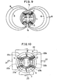
- FIG. 9 is a magnetic flux generated by horizontal coils 2 and 3 within an annular core 1 used as a magnetic core.
- 10 is a yoke and 11 is a conductive wire.
- lla and 11b are magnet shield coils which are wound the conductive wire 11 around non wire-wound portions 10a and 10b of the deflecting yoke 10 and which are electrically connected in series with each other.
- the yoke 10 constructed as mentioned above is mounted on a small-diameter portion 15a at the rear of a C R T 15.
- An electron gun 16 is connected to the portion 15a of the C R T and a plurality of connecting pins 17 are protruding from the electron gun 16 rearward.
- the magnet shield coils lla and llb are wound around the non wire-wound portions 10a and 10b and the magnet shield coils lla and llb produce an opposing magnetic flux 12 (shown by dotted arrows in Fig. 1) which opposes the flux 9 within the annular core 1 to cancel out the magnetic flux 9. Therefore it is avoided that magnetic poles are produced within the annular core 1 and the leakage of magnetic flux is reduced or extinguished.
- the invention can also be embodied, without being restricted to such series-connected circuit, by a parallel-connected circuit in which magnet shield coils 22a, 23a, 22b, and 23b are wound around non wire-wound portions 20a and 20b of the annular core 1 of a deflecting core 20 and magnet shield coils are formed by each of two parallel wires 22 and 23 branching off a wire 21 as shown in Fig. 5 and F ig. 6. And then the opposing magnetic flux 12 cancels out the magnetic flux 9 within the annular core 1.
- the embodiment in the parallel-connected circuit also gives the same effect as the embodiment in the series-connected circuit mentioned above.
- the magnetic flux having its poles within the magnetic core is canceled out by the opposing magnetic flux set up by the magnet shield coils it is possible to eliminate radio interference to various radio wave equipments without employing a large-scaled magnet shield design and to avoid rise in the temperature of the CRT or the whole equipment which would be caused if a large-scaled electromagnetic shielding construction were employed, while maintaining long life and low cost of the CRT equipment.
Abstract
Description
- The present invention relates to improvements of a deflecting yoke for deflecting an electron beam electromagnetically when a high energy electron beam is used in a cathode ray tube (referred to as CRT hereafter).
- Fig. 7 through Fig. 9 are rear elevations showing a prior yoke seen from the rear of the CRT. 1 is an annular core in substantially cylindrical shape into which an electron-gun portion at the rear of the CRT is inserted and which is mounted around an outer circumference of a small-diameter portion of the CRT.
- 2 and 3 are a pair of horizontal coils as first coils disposed substantially horizontally along the inner circumferential surface of the above mentioned
annular core 1. - 4 and 5 are vertical coils as second coils which are wound a conductor wire directly around the above mentioned
core 1 in a so-called "toroidal-winding" using a special coil-winding machine (not shown diagramatically). - The operation of a deflecting yoke in above arrangement is described as follows.
- A horizontal
magnetic flux 6 is set up bycoils magnetic flux 7 is set up byvertical coils - The magnetic field intensity of the aforementioned horizontal
magnetic flux 6 and verticalmagnetic flux 7 vary in response to an amount of current through thehorizontal coils vertical coils solid arrows - The direction of an electron beam passing through a small-diameter portion of the CRT which is inserted into the annular core is deflected by this magnetic field and an image is displayed brightly on the CRT.
- Since the aforementioned horizontal
magnetic flux 6 passes through two semi-circular magnetic paths passing through theannular core 1 as shown in Fig. 9 it causes opposing magnetic poles la and lb to set up at the upper part and the lower part of theannular core 1 respectively. - The polarities of these magnetic poles change from N to S and back to N in alternating fashion and therefore alternating magnetic field is formed in such a way that the
annular core 1 is positioned at a center of the alternating magnetic field. And aleakage flux 8 which is emitted from the yoke outwardly is produced between the poles la and lb. - As the prior deflecting yoke is configured as mentioned above the
leakage flux 8 emitted from the yoke may interfere such radio wave equipments as radio receivers. - A variety of electromagnetic shielding constructions such as magnetic shield design are necessitated to solve this kind of problems and the shielding constructions cause a variety of problems such as rise in the temperature of the CRT display equipments, deteriorated performance due to the temperature, poor durability and shortened life time, and rise in manufacturing cost of the whole equipment.
- The present invention is to solve the above mentioned problems and its object is to provide, by only adding a simple improvement to the prior yoke, a deflecting yoke which is prevented from causing the electromagnetic interference while maintaining long life and low cost of the CRT without drawbacks such as rise in the temperature.
- The deflecting yoke according to the present invention is of a type that additional third coils (referred to as "magnet shield coil* hereafter) are wound around the core in order to cancel out the flux set up in the direction departing outwardly from the core.
- The deflecting yoke according to the present invention works in such a way that the magnetic flux produced within a magnetic core is canceled out by the opposing flux which is set up by the current flowing through the magnet shield coils so that no opposing magnetic poles are set up within the core. And therefore it is possible to thoroughly solve the problem that leakage flux is emitted outside the magnetic core from opposing magnetic poles.
-
- Fig. 1, Fig. 2, and Fig. 3 are a rear elevation, a side elevation, and a perspective view of a deflecting yoke according to one embodiment, respectively.
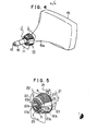
- Fig. 4 is a perspective view of the yoke mounted on CRT in Fig. 1 through Fig. 3.
- Fig. 5 and Fig. 6 are a perspective view and a rear elevation of a yoke of another embodiment according to the present invention, respectively.
- Fig. 7 through Fig. 9 are rear elevations of the yokes according to the prior art.
- Fig. 10 is a rear elevation of still another embodiment according to the present invention.
- A preferred embodiment of the present invention will be described with reference to the accompanying drawings. In Fig. 1 through Fig. 10 like parts or components are denoted by like reference numerals throughout.
- In Fig. 1 through Fig. 3, 9 is a magnetic flux generated by
horizontal coils annular core 1 used as a magnetic core. - 10 is a yoke and 11 is a conductive wire. lla and 11b are magnet shield coils which are wound the
conductive wire 11 around non wire-wound portions yoke 10 and which are electrically connected in series with each other. - 12 is a magnetic flux generated by these magnet shield coils lla and llb within the
annular core 1. - The
yoke 10 constructed as mentioned above is mounted on a small-diameter portion 15a at the rear of a CRT 15. Anelectron gun 16 is connected to theportion 15a of the CRT and a plurality of connectingpins 17 are protruding from theelectron gun 16 rearward. - The operation of the yoke mentioned above is described as follows.
- When a current flows through
vertical coils annular core 1 used as a magnetic core in so-called "toroidal-winding" andhorizontal coils annular core 1, the horizontal flux and the vertical flux are set up respectively and the horizontal flux will set up the magnetic field denoted by anarrow 6 as shown in Fig. 1. - And simultaneously a
magnetic flux 9 is set up within the non wire-wound portions annular core 1. - There used to be a drawback in a prior art that leakage flux results from the
magnetic flux 9. However, in this embodiment, the magnet shield coils lla and llb are wound around the non wire-wound portions flux 9 within theannular core 1 to cancel out themagnetic flux 9. Therefore it is avoided that magnetic poles are produced within theannular core 1 and the leakage of magnetic flux is reduced or extinguished. - Though the above mentioned embodiment shows an example that the magnet shield coils lla and llb are electrically connected in series with each other the invention can also be embodied, without being restricted to such series-connected circuit, by a parallel-connected circuit in which
magnet shield coils wound portions annular core 1 of a deflectingcore 20 and magnet shield coils are formed by each of twoparallel wires wire 21 as shown in Fig. 5 and Fig. 6. And then the opposingmagnetic flux 12 cancels out themagnetic flux 9 within theannular core 1. The embodiment in the parallel-connected circuit also gives the same effect as the embodiment in the series-connected circuit mentioned above. - Further, the same effect can also be obtained by winding the magnet shield coils not around the non wire-
wound portions vertical coils - According to the present invention, because the magnetic flux having its poles within the magnetic core is canceled out by the opposing magnetic flux set up by the magnet shield coils it is possible to eliminate radio interference to various radio wave equipments without employing a large-scaled magnet shield design and to avoid rise in the temperature of the CRT or the whole equipment which would be caused if a large-scaled electromagnetic shielding construction were employed, while maintaining long life and low cost of the CRT equipment.
Claims (3)
Applications Claiming Priority (2)
| Application Number | Priority Date | Filing Date | Title |
|---|---|---|---|
| JP108660/86 | 1986-05-14 | ||
| JP61108660A JPS62268046A (en) | 1986-05-14 | 1986-05-14 | Deflecting yoke |
Publications (2)
| Publication Number | Publication Date |
|---|---|
| EP0245711A2 true EP0245711A2 (en) | 1987-11-19 |
| EP0245711A3 EP0245711A3 (en) | 1990-03-28 |
Family
ID=14490441
Family Applications (1)
| Application Number | Title | Priority Date | Filing Date |
|---|---|---|---|
| EP87106259A Withdrawn EP0245711A3 (en) | 1986-05-14 | 1987-04-29 | Deflecting yoke |
Country Status (4)
| Country | Link |
|---|---|
| US (1) | US4758810A (en) |
| EP (1) | EP0245711A3 (en) |
| JP (1) | JPS62268046A (en) |
| KR (1) | KR910001627B1 (en) |
Cited By (1)
| Publication number | Priority date | Publication date | Assignee | Title |
|---|---|---|---|---|
| EP0281184B1 (en) * | 1987-02-24 | 1994-07-20 | Koninklijke Philips Electronics N.V. | Picture display device having means for compensating stray fields |
Families Citing this family (5)
| Publication number | Priority date | Publication date | Assignee | Title |
|---|---|---|---|---|
| US4922167A (en) * | 1985-10-25 | 1990-05-01 | U.S. Philips Corporation | Picture display device having means for compensating line stray fields |
| US5264706A (en) * | 1991-04-26 | 1993-11-23 | Fujitsu Limited | Electron beam exposure system having an electromagnetic deflector configured for efficient cooling |
| TWI252073B (en) * | 2003-08-26 | 2006-03-21 | Benq Corp | Display |
| CN105674431B (en) * | 2016-04-18 | 2019-02-05 | 珠海格力电器股份有限公司 | A kind of retaining frame component and the air-conditioning with it |
| WO2019090358A1 (en) * | 2017-11-06 | 2019-05-09 | North Carolina State University | Mixed material magnetic core for shielding of eddy current induced excess losses |
Citations (5)
| Publication number | Priority date | Publication date | Assignee | Title |
|---|---|---|---|---|
| US2227029A (en) * | 1937-02-05 | 1940-12-31 | Loewe Radio Inc | Elimination of the magnetic dispersion of transformers |
| US3153171A (en) * | 1960-06-24 | 1964-10-13 | Marconi Co Ltd | Neutralization of orthicon image section from stray line scanning fields |
| US3735193A (en) * | 1970-12-26 | 1973-05-22 | Denki Onkyo Co Ltd | Deflection yoke |
| DE2533818A1 (en) * | 1974-08-08 | 1976-02-19 | Philips Nv | DEFLECTION FOR COLOR TELEVISION SYSTEM |
| JPH06293841A (en) * | 1992-11-26 | 1994-10-21 | Basf Ag | Molded polylactide foam |
Family Cites Families (6)
| Publication number | Priority date | Publication date | Assignee | Title |
|---|---|---|---|---|
| FR1598193A (en) * | 1967-11-21 | 1970-07-06 | ||
| DE2155440C3 (en) * | 1971-11-08 | 1975-01-09 | Albertas Wazlowowitsch Bauschis | Color picture tube with a ferrite core surrounding the tube neck |
| JPS52126105A (en) * | 1976-04-16 | 1977-10-22 | Hitachi Ltd | Data communication system between two data communication systems having indpendent synchronous timing |
| JPS5543701A (en) * | 1978-09-20 | 1980-03-27 | Toshiba Corp | Color image receiving tube |
| JPS57176057A (en) * | 1981-04-23 | 1982-10-29 | Ricoh Co Ltd | Electrophotographic receptor |
| JPS5931088A (en) * | 1982-08-14 | 1984-02-18 | Nippon Telegr & Teleph Corp <Ntt> | Semiconductor laser device |
-
1986
- 1986-05-14 JP JP61108660A patent/JPS62268046A/en active Pending
-
1987
- 1987-03-19 KR KR1019870002480A patent/KR910001627B1/en not_active IP Right Cessation
- 1987-04-14 US US07/038,100 patent/US4758810A/en not_active Expired - Lifetime
- 1987-04-29 EP EP87106259A patent/EP0245711A3/en not_active Withdrawn
Patent Citations (5)
| Publication number | Priority date | Publication date | Assignee | Title |
|---|---|---|---|---|
| US2227029A (en) * | 1937-02-05 | 1940-12-31 | Loewe Radio Inc | Elimination of the magnetic dispersion of transformers |
| US3153171A (en) * | 1960-06-24 | 1964-10-13 | Marconi Co Ltd | Neutralization of orthicon image section from stray line scanning fields |
| US3735193A (en) * | 1970-12-26 | 1973-05-22 | Denki Onkyo Co Ltd | Deflection yoke |
| DE2533818A1 (en) * | 1974-08-08 | 1976-02-19 | Philips Nv | DEFLECTION FOR COLOR TELEVISION SYSTEM |
| JPH06293841A (en) * | 1992-11-26 | 1994-10-21 | Basf Ag | Molded polylactide foam |
Cited By (1)
| Publication number | Priority date | Publication date | Assignee | Title |
|---|---|---|---|---|
| EP0281184B1 (en) * | 1987-02-24 | 1994-07-20 | Koninklijke Philips Electronics N.V. | Picture display device having means for compensating stray fields |
Also Published As
| Publication number | Publication date |
|---|---|
| KR910001627B1 (en) | 1991-03-16 |
| KR870011656A (en) | 1987-12-24 |
| JPS62268046A (en) | 1987-11-20 |
| EP0245711A3 (en) | 1990-03-28 |
| US4758810A (en) | 1988-07-19 |
Similar Documents
| Publication | Publication Date | Title |
|---|---|---|
| US4853588A (en) | Deflection yoke apparatus with means for reducing unwanted radiation | |
| US5049847A (en) | Deflection yoke with auxiliary coils for stray line radiation suppression | |
| EP0366196B1 (en) | Method of manufacturing a saddle-shaped deflection coil for a picture display tube and display tube comprising a deflection system using saddle-shaped deflection coils | |
| EP0245711A2 (en) | Deflecting yoke | |
| US4992697A (en) | Picture display device with magnetizable core means comprising compensation coils | |
| KR0141699B1 (en) | Picture display device with core means comprising compensation coils | |
| EP0291121B1 (en) | Picture display device with stray field compensation means | |
| EP0565120B1 (en) | Cathode-ray tube apparatus | |
| EP0244908B1 (en) | A method of correcting dynamic electron beam misconvergence in a colour display tube and a colour display tube system | |
| EP0090107A1 (en) | Convergence unit for in-line colour cathode ray tube | |
| US3188534A (en) | Convergence coil assembly | |
| EP0228744B1 (en) | In-line colour display tube carrying a deflection unit which presents left-right sided raster correction | |
| EP0283904A1 (en) | Color cathode ray tube apparatus | |
| EP1460673A2 (en) | Cathode ray tube apparatus having velocity modulation coil | |
| US3991338A (en) | Convergence unit having three identical V-shape bent plates for shielding pole shoes | |
| US6888299B2 (en) | Electron gun for cathode ray tube having SVM coil and cathode ray tube using the electron gun | |
| US2901650A (en) | Electromagnetic deflection yoke | |
| KR19990079601A (en) | Deflection yoke for cathode ray tube | |
| GB2187883A (en) | Deflection yoke apparatus with auxiliary coils for reducing unwanted radiation | |
| EP1329935B1 (en) | Cathode ray tube | |
| KR100405212B1 (en) | Deflection yoke | |
| GB2269477A (en) | CRT deflection yoke with printed circuit board | |
| KR100474244B1 (en) | Integrated leakage cancellation and misconvergence correction device of deflection yoke for CRT | |
| KR100407427B1 (en) | Cathode ray tube apparatus comprising deflection yoke | |
| JPH01154442A (en) | Cathode-ray tube display device |
Legal Events
| Date | Code | Title | Description |
|---|---|---|---|
| PUAI | Public reference made under article 153(3) epc to a published international application that has entered the european phase |
Free format text: ORIGINAL CODE: 0009012 |
|
| AK | Designated contracting states |
Kind code of ref document: A2 Designated state(s): DE FR GB NL |
|
| PUAL | Search report despatched |
Free format text: ORIGINAL CODE: 0009013 |
|
| AK | Designated contracting states |
Kind code of ref document: A3 Designated state(s): DE FR GB NL |
|
| 17P | Request for examination filed |
Effective date: 19900820 |
|
| 17Q | First examination report despatched |
Effective date: 19921125 |
|
| STAA | Information on the status of an ep patent application or granted ep patent |
Free format text: STATUS: THE APPLICATION IS DEEMED TO BE WITHDRAWN |
|
| 18D | Application deemed to be withdrawn |
Effective date: 19930608 |
|
| RIN1 | Information on inventor provided before grant (corrected) |
Inventor name: TAMURA, MANABUMITSUBISHI DENKI K.K. |