KR0141699B1 - Picture display device with core means comprising compensation coils - Google Patents
Picture display device with core means comprising compensation coilsInfo
- Publication number
- KR0141699B1 KR0141699B1 KR1019890008046A KR890008046A KR0141699B1 KR 0141699 B1 KR0141699 B1 KR 0141699B1 KR 1019890008046 A KR1019890008046 A KR 1019890008046A KR 890008046 A KR890008046 A KR 890008046A KR 0141699 B1 KR0141699 B1 KR 0141699B1
- Authority
- KR
- South Korea
- Prior art keywords
- plane
- coil
- core
- deflection
- compensation
- Prior art date
Links
Images


Classifications
-
- H—ELECTRICITY
- H01—ELECTRIC ELEMENTS
- H01J—ELECTRIC DISCHARGE TUBES OR DISCHARGE LAMPS
- H01J29/00—Details of cathode-ray tubes or of electron-beam tubes of the types covered by group H01J31/00
- H01J29/46—Arrangements of electrodes and associated parts for generating or controlling the ray or beam, e.g. electron-optical arrangement
- H01J29/70—Arrangements for deflecting ray or beam
- H01J29/72—Arrangements for deflecting ray or beam along one straight line or along two perpendicular straight lines
- H01J29/76—Deflecting by magnetic fields only
-
- H—ELECTRICITY
- H01—ELECTRIC ELEMENTS
- H01J—ELECTRIC DISCHARGE TUBES OR DISCHARGE LAMPS
- H01J29/00—Details of cathode-ray tubes or of electron-beam tubes of the types covered by group H01J31/00
- H01J29/003—Arrangements for eliminating unwanted electromagnetic effects, e.g. demagnetisation arrangements, shielding coils
-
- H—ELECTRICITY
- H01—ELECTRIC ELEMENTS
- H01J—ELECTRIC DISCHARGE TUBES OR DISCHARGE LAMPS
- H01J2229/00—Details of cathode ray tubes or electron beam tubes
- H01J2229/0007—Elimination of unwanted or stray electromagnetic effects
- H01J2229/0015—Preventing or cancelling fields leaving the enclosure
Landscapes
- Physics & Mathematics (AREA)
- Electromagnetism (AREA)
- Video Image Reproduction Devices For Color Tv Systems (AREA)
Abstract
화상 디스플레이 장치는 디스플레이 관과, 편향 유닛 및 디스플레이 스크린의 정면의 공간에서 상기 편향 유닛의 라인 주파수 방사장과 반대 방향으로 향하는 자기 보상장을 발생시키기 위한 보상 코일 시스템을 포함한다. 상기 보상 코일 시스템은 두 개의 코일을 포함하는데, 그 각각은 막대형 코어부에 감겨져 있다. 상기 코어부는 X-Z 평면에 대해서 대칭으로 Y-Z 평면에서 V 형으로 정렬된다. 대안으로, 상기 보상 코일 시스템은 이러한 방식으로 정렬되고 X-Y 평면에 평행하고 상기 X-Y 평면에서 동일한 간격의 평면에 위치되는 두 쌍의 코일을 포함할 수도 있다.The image display apparatus includes a display tube and a compensation coil system for generating a magnetic compensation field directed in a direction opposite to the line frequency radiation field of the deflection unit in the space in front of the deflection unit and the display screen. The compensation coil system comprises two coils, each wound around a rod-shaped core. The core portion is aligned V-shaped in the Y-Z plane symmetrically with respect to the X-Z plane. Alternatively, the compensation coil system may comprise two pairs of coils arranged in this manner and parallel to the X-Y plane and located in planes of equal spacing in the X-Y plane.
Description
본 발명은 디스플레이 관(display tube)을 구비하는 화상 디스플레이 장치에 관한 것으로, 상기 디스플레이 관의 배면부는 전자빔을 발생시키기 위한 장치를 수용하는 원통형의 목부(cylindricalneck)로 구성되고, 상기 디스플레이 관의 정면부는 깔때기 형상으로, 가장 넓은 부분은 정면에 나타나고 형광 디스플레이 스크린을 포함하며, 상기 디스플레이 장치는 디스플레이 스크린 전체에 걸쳐 전자빔을 편향시키기 위해 디스플레이 관의 일부 주위에 장착된 전자기 편향 유닛, 및 라인 주파수 방사장(frequency radiation field)과 반대 방향으로 향하는 자기 보상장(magnetic compensation field)을 발생하기 위한 보상 코일 시스템(compensation coil system)을 또한 포함하며, 상기 편향 유닛은 두 개의 라인 편향 코일 반부(halves)를 구비하는 라인 편향 코일 및 장(field)편향 코일을 구비하고, 각각의 코일 반부는 대칭면의 각 측면에 위치한다.BACKGROUND OF THE INVENTION 1. Field of the Invention The present invention relates to an image display apparatus having a display tube, wherein a rear portion of the display tube is composed of a cylindrical neckneck for receiving a device for generating an electron beam, and the front portion of the display tube is In funnel shape, the widest portion appears in front and comprises a fluorescent display screen, the display device having an electromagnetic deflection unit mounted around a portion of the display tube for deflecting the electron beam across the display screen, and a line frequency radiation field. and a compensation coil system for generating a magnetic compensation field directed in a direction opposite to the radiation field, wherein the deflection unit comprises a line having two line deflection coil halves. Deflection coil and field deflection coil And wherein each of the coil halves is located on each side of the plane of symmetry.
(라일 편향 코일의) 표유장(stray field)을 보상하기 위한 보상 코일 시스템을 구비하는 화상 디스플레이 장치는 EP-A 제 220, 777호로부터 공지되어 있다.An image display apparatus having a compensation coil system for compensating stray fields (of a rail deflection coil) is known from EP-A 220, 777.
최근에, 자기 간섭장에 대한 보다 엄격한 기준이 소정의 형태의 화상 디스플레이 장치, 특히 그 중에서도 모니터에 대해 도입되었는데, 상기 간섭장은 모니터 주위에서 발생한다. 장 편향 코일과 대조적으로 라인 편향 코일이 무선 주파수 전류(10 내지 100 kHz 범위의 주파수)에서 동작하기 때문에 자기 간섭장의 주요 원천(source)은 라인 편향 코일이다. 표유장을 발생시키지 않고 만족스럽게 동작하는 편향 코일을 설계하는 것은 불가능하다. 만약 표유장이 보호 실드(protective shield)에 의해 제거된다면, 디스플레이 관 및 편향 장치의 조합이 디스플레이 스크린 측면 상에서 또한 보호될 때만 상기 실드는 유효하게 될 것이다. 편향 유닛의 외부 자기장은 그다지 강하지 않다 ; 110°의 단색 디스플레이 관의 편향 유닛의 정면(front side)으로부터 50cm의 거리에서 장의 세기는 지구 자기장 세기의 거의 1%로 감소되지만, 중요한 것은 시간에 대한 장의 변화이다. 장의 변화는 다른 전자 장치에서 간섭을 유발시키며, 사람의 건강이 이러한 장에 의해 영향을 받는지를 확인하기 위한 연구가 행해지고 있다. 편향 유닛의 장의 시간 도함수는 라인 주파수의 증가와 함께 증가하여 플라이백(flyback) 주기를 점점 짧게 한다.Recently, stricter criteria for magnetic interference fields have been introduced for some types of image display devices, especially monitors, which occur around the monitor. In contrast to the field deflection coils, the main source of the magnetic interference field is the line deflection coils since the line deflection coils operate at radio frequency currents (frequency in the range of 10 to 100 kHz). It is not possible to design a deflection coil that satisfactorily operates without generating stray fields. If the stray field is removed by a protective shield, the shield will only be effective when the combination of display tube and deflection device is also protected on the display screen side. The external magnetic field of the deflection unit is not very strong; At a distance of 50 cm from the front side of the deflection unit of a 110 ° monochrome display tube, the field strength is reduced to almost 1% of the Earth's magnetic field strength, but what is important is the change in the field over time. Intestinal changes cause interference in other electronic devices, and research is being conducted to determine whether human health is affected by these intestines. The long time derivative of the deflection unit increases with increasing line frequency, making the flyback period shorter and shorter.
라인 편향 표유장의 보상을 위해, 활성화된 경우 보상 자기 쌍극장(dipole field)을 발생하는 보상코일 시스템의 사용은 상술한 특허 공보에서 설명되었다. 이러한 쌍극장은 그 권선이 주로 한 편평한 평면(전류 루프) 내에 위치하는 하나의 코일을 활성화함으로써 획득될 수 있는데, 상기 코일은 정확한 권선수와, 정확한 표면적 및 정확한 방향을 갖는다. 예를들면, 보상 코일을 라인 편향 코일과 직렬 또는 병렬로 배열함으로써 활성화가 이루어질 것이다. 다른 방법으로는, 라인 편향 코일의 양쪽에 위치된 2개의 전류 루프를 활성화시킴으로써 보상 장(compensation field)이 얻어질 수 있는데, 상기 전류 루프는 정확한 권선수와, 정확한 표면적 및 정확한 방향을 가진다. 또한, 상기 경우에 있어서 예를들면, 전류 루프로 구성된 보상 코일을 라인 편향 코일과 직렬 또는 병렬로 배열함으로써 활성화가 이루어질 수 있다.For the compensation of the line deflection stray field, the use of a compensation coil system which, when activated, generates a compensating magnetic dipole field has been described in the above-mentioned patent publication. This dipole can be obtained by activating one coil whose winding is mainly located in one flat plane (current loop), which has the correct number of turns, the correct surface area and the correct direction. For example, activation may be achieved by arranging the compensation coil in series or in parallel with the line deflection coil. Alternatively, a compensation field can be obtained by activating two current loops located on either side of the line deflection coil, which has the correct number of turns, the correct surface area and the correct direction. Also in this case, activation can be achieved, for example, by arranging a compensation coil consisting of a current loop in series or in parallel with the line deflection coil.
보상 코일은 에너지 용량을 감소시키기 위해 되도록 큰 형태를 갖는다.The compensation coil is as large as possible to reduce the energy capacity.
그러나, 많은 형태의 디스플레이 장치(특히 모니터)가 정확한 위치에 큰 코일 시스템을 수용하기 위한 공간이 부족하다는 문제점이 있다. 결과적으로, 상대적으로 작은(아주 작은) 보상 코일이 사용되어야만 하고, 그 결과 방사 보상은 많은 (라인 편향) 에너지를 소비하게 된다. 또한, 보상 코일 시스템이 라인 편향 코일과 직렬로 배열된 경우, 라인 편향 코일의 감도는 해로운 영향을 받는다. 이때 유도(induction)는 증가한다.However, many types of display devices (especially monitors) have a problem in that there is a lack of space for accommodating a large coil system in the correct position. As a result, a relatively small (very small) compensation coil must be used, and as a result radiation compensation consumes a lot of (line deflection) energy. In addition, when the compensation coil system is arranged in series with the line deflection coil, the sensitivity of the line deflection coil is adversely affected. Induction then increases.
본 발명의 목적은, 공지된 방법에 의해 실현되는 것보다 적은 에너지 및 낮은 감도로 라인 편향 코일의 방사장의 보상을 가능하게 하는 방법을 제공하는 것이다.It is an object of the present invention to provide a method that enables compensation of the radiation field of a line deflection coil with less energy and lower sensitivity than realized by known methods.
본 발명에 의하면, 이러한 목적은 서두에서 상술된 형태의 장치가 편향 유닛의 스크린 쪽의 끝에 인접해서 존재하고 적어도 한 쌍의 코어 수단을 포함하는 보상 코일 시스템을 구비하는 점에서 해결되는데, 각 쌍의 코어 수단은 코일을 구비하고 법선이 디스플레이 관의 길이축(longitudinal axis)을 가로지르는 평면에서 확장하는 막대형 자기 코어부를 포함하고, 상기 코어 수단은 상기 대칭 평면에 대해서 대칭적으로 위치되고 그리고 관의 축을 포함하며 대칭 평면을 가로지르는 평면에 대해서 대칭적으로 위치되며, 동일 평면의 코어 수단의 길이축은 90°-φ의 예각으로 동일한 역행점(retrograde point)에서 대칭면을 교차하고, 각 쌍의 코어 수단의 중심은 편향 유닛의 중심 및 디스플레이 스크린 사이에 위치한다.According to the invention, this object is solved in that the device of the type described above at the outset has a compensating coil system which is adjacent to the end of the screen side of the deflection unit and comprises at least a pair of core means, each pair of The core means comprises a rod-shaped magnetic core portion having a coil and extending in a plane whose normal crosses the longitudinal axis of the display tube, the core means being symmetrically positioned with respect to the plane of symmetry and A pair of core means intersecting the plane of symmetry at the same retrograde point with an acute angle of 90 ° -φ, the axis of symmetry being positioned symmetrically with respect to the plane transverse to the plane of symmetry including the axis Is centered between the center of the deflection unit and the display screen.
(환상형) 보상 코일을 구비하는 자화성 물질로 이루어진 막대형 코어 수단의 사용에 기초한 방사 보상에 대한 상기 해결책의 간략함은, 무코어(coreless), 즉 공기-코어의 코일(air-cored coils)의 사용에 기초한, 공지된 어떤 해결책보다도 우수하다. 자화성 물질로 이루어진 코어를 둘러싸는 코일은 공간을 거의 차지하지 않으며 감도의 손실이 작다.The simplicity of this solution to radiation compensation based on the use of rod-shaped core means made of magnetizable material with (annular) compensation coils is coreless, ie air-cored coils. Is superior to any known solution based on the use of The coil surrounding the core made of magnetizable material takes up little space and has a small loss of sensitivity.
본 발명의 범위 내에서, 보상 코일 시스템은, 관의 축을 가로지르는 법선을 가지는 제 1의 평면에서 확장하는 제 1의 코어 수단의 쌍과, 관의 축을 가로지르는 법선을 가지는 제 2의 평면에서 확장하는 제 2의 코어 수단의 쌍을 구비하는데, 상기 제 1 및 2의 평면은 관의 축으로부터 등거리에 위치한다. 실제로 테스트된 구성은 라인 편향 표유장을 효율적으로 보상하면서, 공지된 보상 코일 시스템 보다 편향 감도의 손실이 훨씬 적은 것으로 판단되었다.(예를 들면, 5배만큼 작다).Within the scope of the invention, a compensation coil system extends in a second plane having a pair of first core means extending in a first plane having a normal across the axis of the tube and a normal across the axis of the tube. A second pair of core means, said first and second planes being equidistant from the axis of the tube. Indeed, the tested configuration was found to have a much lower loss of deflection sensitivity than the known compensating coil system while efficiently compensating for the line deflection stray field (eg, as little as five times).
보다 유용한 실시예는, 보상 코일 시스템이 관의 축을 포함하며 라인 편향 코일의 대칭면을 가로지르는 평면에서 확장하는 한 쌍의 코어 수단을 포함하는 것을 특징으로 한다. 이와 같은 방식으로 정렬된 (2개의) 코어 수단은, 상술한 해결책의 (4개의) 코어 수단 보다, 순방향(forwarddirection)으로 보다 큰 유효한 공간을 갖는다. 자기 코어부(magnetic core portions)가 편향 장치의 앞쪽에서 더 앞쪽으로 확장 해감에 따라 보상의 유효성이 보다 커지므로 상기 사항은 매우 중요하다.A more useful embodiment is characterized in that the compensation coil system comprises a pair of core means including an axis of the tube and extending in a plane across the plane of symmetry of the line deflection coil. The (two) core means aligned in this way have a larger effective space in the forwarddirection than the (four) core means of the solution described above. This is very important as the validity of the compensation becomes larger as the magnetic core portions extend from the front of the deflection device to the front.
최후에 언급된 해결책에 있어서, 2개의 코어 수단의 코어부는 되도록 라인 편향 코일을 에워싸는 자기 물질 요크 링(magnetic material yoke ring)과 자기 선속-교환(magnetic flux-exchanging)의 관계로 배열된다. 이때, 요크 링 및 2개의 코어부의 조합은 마치 매우 긴 길이의 하나의 코어부처럼 작용한다. 라인 편향 코일과 및 상기 코일을 둘러싸는 요크 링의 직경이 디스플레이 스크린을 향해 증가하는 사실 때문에, 편향 유닛의 방사 중심은 역학적 중심과 일치하지 않지만, (디스플레이 관의) 편향 유닛의 정면에서 짧은 거리(수 cm)에 위치한다. 이는, 보상 코일 시스템의 방사 중심이 편향 유닛의 방사 중심과 일치하도록 상기 보상 코일(들)을 위치시킬 수 있는 가능성을 공지된 해결책이 제공하지 못한다는 것을 의미한다. 따라서, 보상장(compensation field; 쌍극장(dipole field)의 발생은 더 높은 차수의 자기장(higher order)(선택된 구성에 따라, 4-극장, 6-극장)의 발생을 수반한다. 일반적으로, 부과된 요구 사항을 충족시키기 위해서 이러한 높은 차수의 자기장을 차례로 보상할 필요가 있다. 부가적인 보상 코일 시스템은 이때 필요 되어진다. 보상 코일 시스템의 방사 중심이 편향 유닛의 방사 중심과 일치하지 않는다는 사실을 충분히 보상하도록, 관련 보상 코일을 가지는 자화성 물질의 코어부를 위치시키는 것이 가능하기 때문에 상기 문제점은 본 발명에 의한 장치에서는 나타나지 않는다. 따라서, 각(φ)은, 코어부의 중심을 통과하는 평면 및 편향 유닛의 방사 중심 사이의 거리(z)의 함수로서 조절될 수 있다.In the last mentioned solution, the core parts of the two core means are arranged in a magnetic flux-exchanging relationship with a magnetic material yoke ring which preferably surrounds the line deflection coil. The combination of the yoke ring and the two core portions then acts as one core portion of very long length. Due to the fact that the diameter of the line deflection coil and the yoke ring surrounding the coil increases toward the display screen, the radial center of the deflection unit does not coincide with the mechanical center, but a short distance from the front of the deflection unit (of the display tube) ( Several cm). This means that the known solution does not offer the possibility of positioning the compensation coil (s) such that the radiation center of the compensation coil system coincides with the radiation center of the deflection unit. Thus, the generation of a compensation field (dipole field) involves the generation of a higher order magnetic field (four- and six-field, depending on the configuration chosen). These high order magnetic fields need to be compensated in order to meet the specified requirements, an additional compensation coil system is required at this time, sufficient to ensure that the radiation center of the compensation coil system does not coincide with the radiation center of the deflection unit. This problem does not appear in the device according to the invention, since it is possible to position the core part of the magnetizable material having an associated compensation coil so as to compensate, therefore the angle φ is a plane and deflection unit passing through the center of the core part. It can be adjusted as a function of the distance z between the radiation centers of.
부적합한 4-극 성분을 보상하기 위하여, tan φ=z/y가 되도록 각(φ)이 조절되며, 여기에서 y는 코어부의 중심과 대칭면 사이의 거리이며 z는 코어부의 중심을 통과하는 평면과 편향 유닛의 방사 중심 사이의 거리이다.To compensate for the inadequate four-pole component, the angle φ is adjusted such that tan φ = z / y, where y is the distance between the center of the core and the plane of symmetry and z is the deflection of the plane through the center of the core. The distance between the radiation centers of the units.
본 발명에 따른 보상 코일 시스템의 실제적 접속 방법은, 코일이 동일한 권선 방향을 가지며, 동작에 있어서, 코일이 발생시키는 장(fields)이 동일한 방향을 가지도록 라인 주파수 방사원에 접속되도록 적응되는 것을 특징으로 한다.The actual connection method of the compensation coil system according to the invention is characterized in that the coils are adapted to be connected to a line frequency radiation source such that the coils have the same winding direction and in operation the fields generated by the coils have the same direction. do.
제 1도는 본 발명에 따른 요크 링 및 보상 코일을 가지는 전자기 편향 장치를 구비하는 디스플레이 관을 포함하는 화상 디스플레이 장치의 투시 입면도.1 is a perspective elevation view of an image display device comprising a display tube having an electromagnetic deflection device having a yoke ring and a compensation coil according to the present invention.
제 2도는 요크 링 및 보상 코일 시스템의 정면도.2 is a front view of the yoke ring and compensation coil system.
제 3도는 요크 링 및 보상 코일 시스템의 측면도.3 is a side view of the yoke ring and compensation coil system.
제 4도는 디스플레이 관 및 편향 장치의 수직 단면도.4 is a vertical sectional view of the display tube and the deflection device.
제 5도는 보상 코일 시스템의 접속 방법에 대한 전기 회로도.5 is an electrical circuit diagram of a method of connecting a compensation coil system.
제 6도는 다른 보상 코일 시스템을 가지는 요크 링의 정면도.6 is a front view of a yoke ring having another compensating coil system.
제 7도는 제 6도의 배열을 가지는 디스플레이 관 및 편향 장치를 도시하는 세로 단면도.FIG. 7 is a longitudinal sectional view showing a display tube and a deflection device having the arrangement of FIG.
* 도면의 주요 부분에 대한 부호의 설명 *Explanation of symbols on the main parts of the drawings
2 : 디스플레이 관2: display tube
7 : 요크 링7: yoke ring
8 : 전자기 편향 장치8: electromagnetic deflection device
본 발명의 실시예는 첨부된 도면을 참조로 상세히 설명될 것이다.Embodiments of the present invention will be described in detail with reference to the accompanying drawings.
제 1도는, 캐비넷(1)에 위치하며 본 발명에 따른 보상 코일 시스템(3)을 포함하는 편향 유닛 및 디스플레이 관의 조합에 대한 투시입면도이다. 간략화를 위해 본 발명의 이해에 있어서 중요하지 않은 세부 사항은 생략되었다.1 is a perspective elevational view of a combination of a deflection unit and a display tube, which is located in a cabinet 1 and comprises a compensating
디스플레이 관(2)은 원통형 목부(5) 및 깔때기형 부분(원추형)(6)을 가지는데, 가장 넓은 부분은 관의 정측면에 존재하며 디스플레이 스크린(도시되지 않음)을 구비한다.The
디스플레이 스크린은 인광물질(phosphors)을 포함하는데, 상기 인광물질은 전자와 충돌할 때 소정의 칼라로 발광한다. 상기 목부(5)의 배면부는 전자총 시스템을 수용한다. 상기 목부(5) 및 깔때기형 부분(6) 사이의 전이 영역에서, 개략적으로 도시된 전자기 편향 유닛(8)이 관 위에 정렬되며. 상기 유닛은 수평 방향(X)으로 전자빔을 편향하기 위한 요크 링(7) 내부에 라인 편향 코일 (보이지 않음)을 포함한다. 상기 라인 편향 코일은 일반적으로 2개의 새들형(saddle-shaped) 코일 반부를 구비하며, 상기 코일 반부는 대칭 평면(X-Z 평면)의 각 측면상에 위치한다. 동작 조건에 있어서, 10 내지 100KHz의 주파수, 예를들면 대략 64KHz의 주파수를 가지는 톱니파 전류는 상기 코일 반부를 통과한다. 일반적으로, 라인 편향 코일은 요크 링으로 칭해지는 연자기(soft-material) 물질의 환상 코어 소자(annular core element)에 의해 둘러싸여진다.Display screens include phosphors, which emit light in a predetermined color when they collide with electrons. The back of the neck 5 houses the electron gun system. In the transition region between the neck (5) and the funnel portion (6), an electromagnetic deflection unit (8) schematically shown is arranged above the tube. The unit comprises a line deflection coil (not shown) inside the
요크 링을 구비하는 라인 편향 코일의 방사장이, 요크 링을 가지지 않는 코일의 방사장과 동일한 크기이며 방향이 반대일 때, 라인 편향 코일은 먼거리에 대해서 소정의 자기 모멘트를 가지는 전류 루프로서 가정될 수 있다.When the radiation field of a line deflection coil with a yoke ring is the same size as the radiation field of a coil without a yoke ring and is opposite in direction, the line deflection coil can be assumed as a current loop with a predetermined magnetic moment over long distances. .
오크 링을 가지지 않는 라인 편향 코일의 방사 중심에서의 자기장(Bo)은 약 30가우스로 계산될 수 있다. 요크 링을 가지는 실제의 편향 코일의 자기장은 상기 값의 약 2배이다.The magnetic field Bo at the radiation center of the line deflection coil without oak ring can be calculated to be about 30 gauss. The magnetic field of an actual deflection coil with a yoke ring is about twice that value.
제 2도 및 제 3도에서 도시된 바와 같이, 코어부 상에 감겨진 코일을 가지는 코어 수단을 구비하는 보상 코일 시스템(3)은 상기 방사장을 보상하기 위해 사용된다.As shown in FIGS. 2 and 3, a
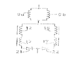
제 2도는 본 발명에 따른 보상 코일 시스템(3)과 결합된, 제 1도의 디스플레이 관(2)의 요크 링(7)의 정입면도이며, 제 3도는 측면도이다. 대칭면(X-Z)에 대해 대칭적으로 위치되는 2개의 라인 편향 코일 반부(9a 및 9b)(점선으로 표시됨)는 대부분 요크 링(7)내에 배열된다. 보상 코일 시스템(3)은 보상 코일(12 및 13)을 구비하는 두 개의 코어부(14 및 15)를 갖는 제 1의 쌍의 코어 수단(10), 및 보상 코일(16 및 17)을 구비하는 두 개의 코어부(18 및 19)를 갖는 제 2의 쌍의 코어 수단(11)을 포함한다. 디스플레이 관 외부의 라인 편향 코일에 의해 발생되는, 특히 디스플레이 스크린의 정측면 상에서의 표류장(방사장)은 정확한 방식으로 보상 코일 시스템을 활성화시킴으로써 보상될 수 있다. 상기 코어 수단의 쌍(10)은 법선이 관의 축(Z)를 횡단하는 평면(α)에서 확장한다. 코어 수단의 쌍(11)은 법선이 관의 축(Z)을 횡단하는 평면(β)에서 확장한다. 상기 평면(α 및 β)은 관의 축(Z)으로부터 등거리에 위치한다.FIG. 2 is a front elevational view of the
제 3도에서 도시된 바와 같이, 코어부(14 및 15)(18 및 19)는 X-Z 평면에 평행이고 상기 코어부의 중심(M)을 통과하는 라인에 대해 일정한 각으로 경사를 이룬다. 경사의 범위는 편향 유닛의 방사 중심으로부터 상기 평면의 거리에 관계된다. 이것은 제 4도를 참조로 상세히 설명될 것이다.As shown in FIG. 3, the
라인 편향 코일(9a 및 9b)의 간섭장(intefering field)은 관(2)에서 대략적으로 쌍극자로 간주될 수도 있다(즉 전류 루프(20)). 바꾸어 말하면, 라인 편향 코일(9a 및 9b)의 직경이 디스플레이 스크린(4)을 향해 증가하므로, 라인 편향 코일의 방사장의 중심(C)는 라인 편향 코일의 앞에 위치한다.The interference field of the line deflection coils 9a and 9b may be regarded as approximately dipole in the tube 2 (ie current loop 20). In other words, since the diameters of the line deflection coils 9a and 9b increase toward the display screen 4, the center C of the radiation field of the line deflection coil is located in front of the line deflection coil.
따라서, 중요한 문제점은, 배치 가능한 보상 코일의 방사 중심이 어떻게 라인 편향 코일의 (가상의) 방사 중심과 일치하도록 만들어져야 하는가 라는 것이다. 상기 중심이 일치하지 않는다면, 쌍극 방사장은 보상될 수 있지만, 예를들면 4-극장 성분이 유도된다.Thus, an important problem is how the radiation center of the deployable compensating coil should be made to coincide with the (virtual) radiation center of the line deflection coil. If the centers do not coincide, the dipole radiation field can be compensated, but for example a four-pole component is derived.
본 발명은 상기 문제점을 인식하여, 완전히 새로운 보상 코일 배열의 설계를 유도한다. 한 실시예는, 자화성 물질로된 막대형 코어부(14, 15, 18 및 19)상에 감겨진 4개의 보상 코일(12, 13, 16 및 17)을 이용한다.(제 2 및 제 3도).The present invention recognizes the above problem and leads to the design of a completely new compensation coil arrangement. One embodiment uses four
코어부(14, 15, 18 및 19)(의 축)는 X-Z 평면에서 대해 90°-α의 각으로 뻗어있다. 유도된 4-극장 성분이 가능한한 많이 보상될 수 있도록 하기 위해서, φ는 tan φ = z/y 의 관계식이 만족되도록 조정될 수 있는데, 여기서 z는 코어부 (14, 15, 18 및 19)의 중심을 통과하는 평면과 방사 중심(C) 사이의 거리이며, y는 코어부(14, 15, 18 및 19)의 중심(M)과 X-Z 평면 사이의 거리이다. 소정의 응용에 있어서, 막대형 코어부(14, 15, 18 및 19)는 60mm의 길이 및 5mm의 직경을 가지며, 4C6 페라이트(ferrite)로 만들어진다. 예를들면, 5 내지 10cm 사이의 막대의 길이는 실제적으로 적합한 것으로 판명되었다. 상기 코어부(14, 15, 18 및 19)는 (유도와 관련해서) 한계 권선수를 가지며, 되도록, 코어부의 길이 방향으로 뻗어가는 코일(12, 13, 16 및 17)에 의해 둘러싸여진다.The
랜딩 에러(landing error) 정정의 목적으로 막대형 코어부의 반대 단부에 영구자석이 배열된다.Permanent magnets are arranged at opposite ends of the rod-shaped cores for the purpose of correcting landing errors.
막대형 코어부상에 감겨진 보상 코일을 사용할 때 랜딩 에러의 영향을 감소 시킬 수 있는 또 다른 방법은, 두 개의 다이오드를 가지는 구성을 부가하는 것이다. 원리에 있어서, 보상 코일쌍은 제 5도에서 개략적으로 도시된 바와 같이 병렬로 배열되는데, 2개의 병렬로 배열된 라인 편향 코일(9a 및 9b)은 2개의 병렬로 배열된 보상 코일쌍(12, 13 및 16, 17)과 직렬로 접속된다. 다이오드(21 및 22)는, 전자빔이 디스플레이 스크린상에서 오른쪽으로 편향되는 경우, 라인 편향 전류가 좌측의 보상 코일 브랜치를 주로 통과하도록 하며, 그 역도 가능하다.Another way to reduce the effects of landing error when using a compensation coil wound on a rod core is to add a configuration with two diodes. In principle, the compensating coil pairs are arranged in parallel as schematically shown in FIG. 5, where the two parallel arranged line deflection coils 9a and 9b are arranged in two parallel compensating coil pairs 12, 13, 16, and 17) in series.
제 6도는 본 발명에 따른 장치의 또 다른 실시예에서 사용되기에 적합한 보상 코일 배열을 가지는 요크 링(27)의 정입면도이다. 대칭 평면(X-Z)에 대해 대칭으로 위치한 2개의 라인 편향 코일 반부(29a 및 29b)는 대부분 요크 링(27)내에 배열된다. 상기 경우에 있어서, 보상 코일 시스템은, 보상 코일(25)을 구비하는 자기 코어부(23) 및 보상 코일(26)을 구비하는 자기 코어부(24)로 이루어지는 한 쌍의 코어 수단(28 및 29)을 구비한다. 상기 코어 수단(28 및 29)은 Y-Z 평면상에서 확장하며 X-Z 평면에 대해 대칭적으로 정렬된다. 목부(35) 및 깔때기형 부분(36)을 구비하는 디스플레이 관(34)을 도시하는 제 7도에서 알 수 있는 바와 같이, 상기 코어 수단(28 및 29)은 90°-φ 의 각도로 동일한 역행점에서 X-Z 평면을 가로지르도록 Y-Z 평면에 위치한다.6 is a front elevational view of
제 6 및 7도에서 도시된 보상 코일 배열의 장점은, 코어부(23 및 24) 주위에 코일을 감고 라인 편향 코일 반부(37a 및 37b)의 리드-아웃(lead-out)을 사용하는 것에 의해 간단하게 코일(25 및 26)이 형성될 수 있다는 것이다.The advantage of the compensation coil arrangement shown in FIGS. 6 and 7 is that by winding the coil around the
또 다른 장점은, 자기선속-결합 관계를 가지도록 요크 링(27)에 대해 코어부(23 및 24)를 배열할 수 있다는 것이다. 즉, 긴 길이의 연속 코어부가 형성될 수 있으며 다른 경우에서보다 적은 편향 에너지를 필요로 한다.Another advantage is that the
또 다른 장점은 다이오드를 가지는 여분의 회로 형태(제 5도)가 사용될 필요가 없다는 것이다.Another advantage is that an extra circuit form with a diode (figure 5) does not have to be used.
내용 없음No content
Claims (9)
Applications Claiming Priority (4)
| Application Number | Priority Date | Filing Date | Title |
|---|---|---|---|
| NL8801512 | 1988-06-14 | ||
| NL8801512A NL8801512A (en) | 1988-06-14 | 1988-06-14 | Picture display device with compensation coils - has two coils wound on rod-shaped core portion arranged in v formation |
| NL8802802A NL8802802A (en) | 1988-11-15 | 1988-11-15 | Picture display device with compensation coils - has two coils wound on rod-shaped core portion arranged in v formation |
| NL8802802 | 1988-11-15 |
Publications (2)
| Publication Number | Publication Date |
|---|---|
| KR900001259A KR900001259A (en) | 1990-01-31 |
| KR0141699B1 true KR0141699B1 (en) | 1998-06-01 |
Family
ID=26646390
Family Applications (1)
| Application Number | Title | Priority Date | Filing Date |
|---|---|---|---|
| KR1019890008046A KR0141699B1 (en) | 1988-06-14 | 1989-06-12 | Picture display device with core means comprising compensation coils |
Country Status (6)
| Country | Link |
|---|---|
| US (1) | US5036250A (en) |
| EP (1) | EP0346972B1 (en) |
| JP (1) | JP2781207B2 (en) |
| KR (1) | KR0141699B1 (en) |
| CN (1) | CN1018224B (en) |
| DE (1) | DE68911762T2 (en) |
Families Citing this family (12)
| Publication number | Priority date | Publication date | Assignee | Title |
|---|---|---|---|---|
| KR920001582Y1 (en) * | 1989-12-23 | 1992-03-05 | 삼성전관 주식회사 | Deflection yoke |
| IT1248761B (en) * | 1990-06-08 | 1995-01-27 | Fimi Srl | COMPENSATION CIRCUIT OF THE HORIZONTAL COMPONENT OF THE TERRESTRIAL MAGNETIC FIELD FOR CINESCOPE COLOR OF HIGH RESOLUTION MONITORS |
| US5027819A (en) * | 1990-07-12 | 1991-07-02 | Biomagnetic Technologies, Inc. | Measurement of visually induced biomagnetic responses |
| KR100243955B1 (en) * | 1991-10-30 | 2000-02-01 | 요트.게.아. 롤페즈 | Deflection yoke apparatus with means for reducing leaking magnetic fields |
| EP0540096B1 (en) * | 1991-10-30 | 1996-01-03 | Koninklijke Philips Electronics N.V. | Deflection yoke apparatus with means for reducing leaking magnetic fields |
| US5399939A (en) * | 1992-01-03 | 1995-03-21 | Environmental Services & Products, Inc. | Magnetic shield with cathode ray tube standoff for a computer monitor |
| US5836775A (en) * | 1993-05-13 | 1998-11-17 | Berg Tehnology, Inc. | Connector apparatus |
| JP3114787B2 (en) * | 1994-09-30 | 2000-12-04 | 三菱自動車工業株式会社 | Exhaust brake device |
| US5959392A (en) * | 1995-01-24 | 1999-09-28 | International Business Machines Corporation | Cancellation coil arrangement for reducing stray magnetic field emissions from CRT displays |
| KR100192233B1 (en) * | 1995-11-30 | 1999-06-15 | 구자홍 | Deflection yoke for cathode ray tube |
| TWI252073B (en) * | 2003-08-26 | 2006-03-21 | Benq Corp | Display |
| CN112382479B (en) * | 2020-10-21 | 2022-09-23 | 惠州市明大精密电子有限公司 | I-shaped inductor and manufacturing method thereof |
Family Cites Families (2)
| Publication number | Priority date | Publication date | Assignee | Title |
|---|---|---|---|---|
| US4853588A (en) * | 1986-09-05 | 1989-08-01 | Denki Onkyo Co., Ltd. | Deflection yoke apparatus with means for reducing unwanted radiation |
| JPH06319740A (en) * | 1993-05-14 | 1994-11-22 | Shimadzu Corp | Ultrasonic diagnostic apparatus |
-
1989
- 1989-05-31 US US07/359,319 patent/US5036250A/en not_active Expired - Lifetime
- 1989-06-08 DE DE68911762T patent/DE68911762T2/en not_active Expired - Fee Related
- 1989-06-08 EP EP89201464A patent/EP0346972B1/en not_active Expired - Lifetime
- 1989-06-12 CN CN89103988A patent/CN1018224B/en not_active Expired
- 1989-06-12 KR KR1019890008046A patent/KR0141699B1/en not_active IP Right Cessation
- 1989-06-14 JP JP1149740A patent/JP2781207B2/en not_active Expired - Lifetime
Also Published As
| Publication number | Publication date |
|---|---|
| JPH0233836A (en) | 1990-02-05 |
| DE68911762T2 (en) | 1994-07-07 |
| KR900001259A (en) | 1990-01-31 |
| EP0346972B1 (en) | 1993-12-29 |
| US5036250A (en) | 1991-07-30 |
| EP0346972A1 (en) | 1989-12-20 |
| JP2781207B2 (en) | 1998-07-30 |
| CN1018224B (en) | 1992-09-09 |
| CN1038900A (en) | 1990-01-17 |
| DE68911762D1 (en) | 1994-02-10 |
Similar Documents
| Publication | Publication Date | Title |
|---|---|---|
| KR940006263B1 (en) | Picture display device with interference suppression means | |
| KR0141699B1 (en) | Picture display device with core means comprising compensation coils | |
| EP0258891B1 (en) | Deflection yoke apparatus with means for reducing unwanted radiation | |
| EP0327161B1 (en) | Picture display device with magnetizable core means comprising compensation coils | |
| CN102592926A (en) | X-ray tube with high speed beam steering electromagnets | |
| EP0291121B1 (en) | Picture display device with stray field compensation means | |
| KR930022446A (en) | Cathode ray tube device | |
| US4758810A (en) | Deflecting yoke | |
| US4922167A (en) | Picture display device having means for compensating line stray fields | |
| KR960000348B1 (en) | Picture display device | |
| US5220241A (en) | Deflection yoke having horizontal auxiliary coils for reducing unnecessary radiant magnetic field | |
| KR960000455B1 (en) | Crt | |
| US5432492A (en) | Deflection yoke apparatus with auxiliar coils to compensensate magnetic leakage | |
| EP0540096B1 (en) | Deflection yoke apparatus with means for reducing leaking magnetic fields | |
| KR950009660Y1 (en) | Deflection yoke of crt | |
| GB2187883A (en) | Deflection yoke apparatus with auxiliary coils for reducing unwanted radiation | |
| NL8801512A (en) | Picture display device with compensation coils - has two coils wound on rod-shaped core portion arranged in v formation | |
| KR920005005B1 (en) | Magnetic shunt for deflection yokes | |
| NL8800884A (en) | Picture display device with magnetisable core - has compensation coil system with core of magnetisable material positioned between display screen and deflection unit | |
| NL8802802A (en) | Picture display device with compensation coils - has two coils wound on rod-shaped core portion arranged in v formation | |
| JPH0426040A (en) | Deflector device for cathode-ray tube | |
| NL8800540A (en) | Picture display device with magnetisable core - has compensation coil system with core of magnetisable material positioned between display screen and deflection unit |
Legal Events
| Date | Code | Title | Description |
|---|---|---|---|
| A201 | Request for examination | ||
| E902 | Notification of reason for refusal | ||
| E701 | Decision to grant or registration of patent right | ||
| GRNT | Written decision to grant | ||
| FPAY | Annual fee payment |
Payment date: 20020226 Year of fee payment: 5 |
|
| LAPS | Lapse due to unpaid annual fee |