EP0245416B1 - Method for treating ascending dampness in walls and electronical device for carrying out this method - Google Patents
Method for treating ascending dampness in walls and electronical device for carrying out this method Download PDFInfo
- Publication number
- EP0245416B1 EP0245416B1 EP19860906845 EP86906845A EP0245416B1 EP 0245416 B1 EP0245416 B1 EP 0245416B1 EP 19860906845 EP19860906845 EP 19860906845 EP 86906845 A EP86906845 A EP 86906845A EP 0245416 B1 EP0245416 B1 EP 0245416B1
- Authority
- EP
- European Patent Office
- Prior art keywords
- wall
- tubes
- bundles
- rods
- circuit
- Prior art date
- Legal status (The legal status is an assumption and is not a legal conclusion. Google has not performed a legal analysis and makes no representation as to the accuracy of the status listed.)
- Expired - Lifetime
Links
Images


Classifications
-
- E—FIXED CONSTRUCTIONS
- E04—BUILDING
- E04B—GENERAL BUILDING CONSTRUCTIONS; WALLS, e.g. PARTITIONS; ROOFS; FLOORS; CEILINGS; INSULATION OR OTHER PROTECTION OF BUILDINGS
- E04B1/00—Constructions in general; Structures which are not restricted either to walls, e.g. partitions, or floors or ceilings or roofs
- E04B1/62—Insulation or other protection; Elements or use of specified material therefor
- E04B1/70—Drying or keeping dry, e.g. by air vents
- E04B1/7007—Drying or keeping dry, e.g. by air vents by using electricity, e.g. electro-osmosis
Definitions
- the present invention relates to a method of treating rising humidity in walls, as well as an electronic device for the implementation of this method.
- the present invention aims to interrupt this stack effect and, thereby, the rise of humidity in the walls by reversing the potential differences and closing the capillaries of the wall.
- holes or grooves are made in the walls, into which are introduced assemblies in the form of bars, tubes or metal beams.
- any conductive body brought into contact with the ground is negatively charged.
- electrochemical methods are used, based on the treatment of the rising humidity of a wall by the passage of a direct current using metallic electrodes in the form bars, tubes or bundles, introduced into the wall, and possibly sealed using specific mortars, aiming either to cancel or even to reverse the potential difference existing in the wall, and thus the current of responsible solvated ions water transport, or to seal the capillaries using a sealing material in the form of powder, the grains of which are diffused in the wall.
- the metal electrodes are then connected to the outside of the wall in order to form a closed electrical circuit, the wall constituting a part of this electrical circuit.
- the user in the case of the potential reversal in the wall, the user must continually supply energy to maintain the process. This involves considerable expenditure.
- the cancellation or inversion of potential necessarily leads either to the dissolution of one of the two electrodes by electrolysis, or to a deposit of insulating oxides on the two electrodes and therefore to an interruption of the process.
- the problem posed by the present invention therefore consists in devising a method for treating the rising humidity in the walls using electrodes, in the form of bars, tubes or bundles, introduced into orifices formed in said walls, simultaneously realizing, on the one hand, the rapid obturation of the capillaries of said walls and, on the other hand, the elimination, in the long term, of the electric pump effect, mainly responsible for the rise of humidity in the walls, without having to continually supply energy and without the electrodes oxidizing or disintegrating, and without moisture accumulating in the foundations, so as to result in a lasting drying of said walls.
- the method of treating rising humidity in the walls consists, in particular, in previously drilling at least one orifice in the said walls, in introducing at least one tube, bar or metallic beam therein, the said method being characterized in that it mainly comprises two distinct treatment phases, namely, on the one hand, an energy supply phase consisting, after having added a catalysis element in the orifices 6 in addition to the bars, tubes or beams 7, to send electrical pulses, supplied by an electronic circuit 12, onto said tubes, bars or beams 7, thus simultaneously producing, on the one hand, an accumulation of electrostatic charges at the level of bars, tubes or beams 7 , and, on the other hand, thanks to a phenomenon of resonance of said electronic circuit 12 with the proper internal circuit of the wall 3, a polarization at the level of the intracapillary electrolyte of the wall, resulting t depositing insoluble silico-calcium salts on the walls of the capillaries of the foundations, and carrying out measurements to control the humidity level 4 and, on the other hand
- the process which is the subject of the invention consists, firstly, in implanting obliquely or vertically a series of bars, tubes or bundles 7 in a wall 3 at calculated distances to allow field forces to be recovered, these elements 7 being connected to the electronic circuit 12 pulse generator via a power supply box 13 for the duration of the energy supply phase, and disconnected during the electrostatic phase.
- a catalysis element for the intracapillary physico-chemical reaction for closing the pores consisting of a powder formed from copper metal in very fine particles, zeolite and oxylith, if local conditions require it.
- the electrostatic phase mainly consists in disconnecting the bars, tubes or bundles 7 from the electronic circuit 12 and in maintaining the potentials in the wall 3 by the electrostatic action of the bars, tubes. or bundles 7.
- the invention also relates to an electronic device for implementing the method, comprising metal electrodes in the form of bars, tubes or bundles, introduced into the wall to be dried, possibly sealed using specific mortars, and connected together outside the wall to form a closed electrical circuit, characterized in that said bars, tubes or bundles are connected together outside the wall by means of an electronic generator 12 pulse generator and are constituted, as shown in FIG.
- the electronic circuit 12 comprises a step-down transformer 17, connected to the mains by means of a switch 15 and a fuse 16, supplying a diode bridge 18, one output of which is earthed 26, and the other of which is connected to a circuit formed by three resistors 19, 20, 24, one of which 19 constitutes an intensity regulator, as well as a shunt 25 and a control ammeter 22, two light-emitting diodes 21, 23 controlling the balance of said electronic circuit 12.
- the electronic circuit 12 generates pulses of positive polarity, at a variable voltage, suitable under local conditions, and from 5 to 15 milli-amperes, at a frequency of 100 Hertz for a tube, bar or beam 7, depending on the set of diodes 18, each bar, tube or beam 7 being supplied via a diode 29, connected in series.
- the diode 29 is located at the top of each bar, tube or bundle 7, to electrically balance the entire installation of the system, according to the evolution of the resistivity of the wall 3 during the energy supply phase of the process, the supply taking place in series.
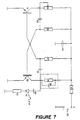
- the electronic device for implementing the method further comprises, in the case of treatments of walls in direct contact with water, an electronic circuit 45 multivibrator, represented in FIG. 7, performing an automatic tuning with the internal circuit specific to the wall 3, according to the evolution of the resistances and capacities of the latter over time, in order to maintain the state of resonance.
- the electromagnetic field obtained makes it possible to implement an important ionic drive process, for which the process comprises two phases.
- the principle is to send pulses under a variable voltage, adapted to local conditions, of positive polarity, under an amperage of 5 to 15 milli-amperes (depending on the materials of the wall) at a frequency of 100 Hertz.
- the zeolite activates the catalyst by the well-known phenomenon of intercalation in a lamellar silicate. If necessary or add oxylithe to provide nascent oxygen on contact with the wall water to avoid the accumulation of hydrogen coming from the water molecules which will have undergone electrolysis.
- Walls in direct contact with a liquid sheet require another electronic circuit to obtain the above-mentioned result.
- This additional circuit is, by consti kills a multivibrator whose frequency and duty cycle are automatically adjusted after initial calibration. It is supplied with a continuous voltage (conventional power supply) and enables the bars to be supplied with an intensity of 5 mA to 1.5 A; it is thus complementary to the electronic pulse generator circuit.
- the load resistance, as well as the "parasitic capacity" offered by the wall give us the first element of the oscillator as the load resistance of the transistor T2-
- the transistor T1 will have its load adjusted by the resistance R1 so as to return the shape starting wave as symmetrical as possible (duty cycle 50/50, in rectangular form).
- the transistors T1 and T2 being correctly polarized by the basic resistors RG1 and RG2, it suffices to react the astable oscillator by the capacitors C1 and C2.
- the system therefore enters an oscillation tuned to a frequency determined by the aircraft according to the resistivity on the wall.
- RL is the resistance limiting the starting intensity at the start of the drying and also depending on the number of bars, the capacitance C 44 ensures decoupling on the supply of the transistors.
- the LED circuit consists of the capacitor C3, the resistor R3 and the diode D3, it is only used to visualize that the device is oscillating correctly. Indeed, in the absence of oscillations, the capacitor C3 is not conductive and, therefore, does not supply the LED diode, R3 serving to limit the current in the diode.
- the oscillator can stop completely.
- the pulses sent allow the accumulation of electrostatic charges in the dielectric of the bars, producing a strong movement of the solvated ions (therefore of their crown of dipolar water molecules) towards the evaporation surfaces of the wall.
- An inversion of the updraft inside the capillaries is also created by an identical phenomenon.
- the bars are introduced into the walls according to precise data calculated to ensure an efficient and gap-free recovery of their radial radiation.
- the process is likely to retain its strong activity beyond the ten-year period, the bars being insensitive to electrolysis.
- the output pulses are of variable voltage, adapted to local circumstances, and at 5 to 15 milliamps per bar 7.
- the shape of the output waves is jagged at a frequency of 100 Hertz.
Landscapes
- Engineering & Computer Science (AREA)
- Architecture (AREA)
- Chemical & Material Sciences (AREA)
- Chemical Kinetics & Catalysis (AREA)
- Electrochemistry (AREA)
- Water Supply & Treatment (AREA)
- Physics & Mathematics (AREA)
- Electromagnetism (AREA)
- Civil Engineering (AREA)
- Structural Engineering (AREA)
- Physical Or Chemical Processes And Apparatus (AREA)
Abstract
Description
La présente invention concerne un procédé de traitement de l'humidité ascendante dans les murs, ainsi qu'un dispositif électronique pour la mise en oeuvre de ce procédé.The present invention relates to a method of treating rising humidity in walls, as well as an electronic device for the implementation of this method.
Cette humidité, qui provient du sol, voit l'action des phénomènes d'osmose et de capillarité relayée et largement amplifiée par l'apparition de différences de potentiel à l'intérieur des murs, créant un effet de pile constant.This humidity, which comes from the ground, sees the action of the phenomena of osmosis and capillarity relayed and largely amplified by the appearance of potential differences inside the walls, creating a constant pile effect.
La présente invention a pour but d'interrompre cet effet de pile et, par là même, l'ascension de l'humidité dans les murs par l'inversion des différences de potentiel et l'obturation des capillaires du mur.The present invention aims to interrupt this stack effect and, thereby, the rise of humidity in the walls by reversing the potential differences and closing the capillaries of the wall.
Pour ce faire, des trous ou des saignées sont pratiqués dans les murs, dans lesquels on introduit des montages sous forme de barres, tubes ou faisceaux métalliques. Or, selon le principe de Coulomb, tout corps conducteur mis en contact avec le sol se charge négativement.To do this, holes or grooves are made in the walls, into which are introduced assemblies in the form of bars, tubes or metal beams. However, according to the Coulomb principle, any conductive body brought into contact with the ground is negatively charged.
En effet, dans les constructions, du fait de la présence de nombreux circuits électriques, d'appareils ménagers ou audiovisuels, existent des courants dits "vagabonds", susceptibles d'inverser la. polarité des barres, courants qui sont à l'origine d'échecs dans les procédés utilisés actuellement. De même, le déplacement des véhicules (faits d'un grand nombre de pièces d'acier plus ou moins aimantées) dans le champ magnétique terrestre produit inévitablement des courants induits (dits de Foucault) qui engendrent à leur tour des champs magnétiques variables.In fact, in constructions, due to the presence of numerous electrical circuits, household or audiovisual appliances, there are so-called "stray currents", capable of reversing the. polarity of the bars, currents which are at the origin of failures in the processes currently used. Likewise, the movement of vehicles (made of a large number of more or less magnetized pieces of steel) in the Earth's magnetic field inevitably produces induced currents (so-called eddy currents) which in turn generate variable magnetic fields.
Dans le document "Elektrophysikalische Verfahren zur Mauertrockenlegung, Teil 1", on utilise des méthodes électrochimiques, basées sur le traitement de l'humidité ascendante d'un mur par le passage d'un courant continu à l'aide d'électrodes métalliques sous forme de barres, tubes ou faisceaux, introduites dans le mur, et éventuellement scellées à l'aide de mortiers spécifiques, visant, soit à annuler ou même à inverser la différence de potentiel existant dans le mur, et ainsi le courant d'ions solvatés responsables du transport d'eau, soit à obturer les capillaires à l'aide d'une matériau d'étanchéité sous forme de poudre, dont les grains sont diffusés dans le mur. Les électrodes métalliques sont alors reliées à l'extérieur du mur afin de former un circuit électrique fermé, le mur constituant une partie de ce circuit électrique.In the document "Elektrophysikalische Verfahren zur Mauertrockenlegung, Teil 1", electrochemical methods are used, based on the treatment of the rising humidity of a wall by the passage of a direct current using metallic electrodes in the form bars, tubes or bundles, introduced into the wall, and possibly sealed using specific mortars, aiming either to cancel or even to reverse the potential difference existing in the wall, and thus the current of responsible solvated ions water transport, or to seal the capillaries using a sealing material in the form of powder, the grains of which are diffused in the wall. The metal electrodes are then connected to the outside of the wall in order to form a closed electrical circuit, the wall constituting a part of this electrical circuit.
Mais ces procédés ne proposant pas une solution durable dans le temps.But these processes do not offer a lasting solution over time.
En effet, dans le cas de l'inversion du potentiel dans le mur, l'utilisateur doit continuellement fournir de l'énergie pour entretenir le processus. Ceci entraîne des dépenses considérables. De plus, l'annulation ou l'inversion de potentiel aboutit nécessiarement, soit à la dissolution d'une des deux électrodes par électrolyse, soit à un dépôt d'oxydes isolant sur les deux électrodes et donc à une interruption du processus.Indeed, in the case of the potential reversal in the wall, the user must continually supply energy to maintain the process. This involves considerable expenditure. In addition, the cancellation or inversion of potential necessarily leads either to the dissolution of one of the two electrodes by electrolysis, or to a deposit of insulating oxides on the two electrodes and therefore to an interruption of the process.
Dans le cas de l'obturation des capillaires par un matériau d'étanchéité, il est impossible de supprimer entièrement l'ascension de l'humidité dans le mur, l'effet de pile n'étant pas interrompu. On aboutit, par contre, à un stockage important d'eau dans les parties basses du mur, et donc à un pourrissement accéléré des fondations du fait de la rétention d'eau à ce niveau.If the capillaries are blocked with a sealing material, it is impossible to completely suppress the rise in humidity in the wall, the stack effect not being interrupted. On the other hand, this leads to a large storage of water in the lower parts of the wall, and therefore to an accelerated decay of the foundations due to the retention of water at this level.
Le problème posé par la présente invention consiste donc à concevoir un procédé de traitement de l'humidité ascendante dans les murs à l'aide d'électrodes, sous forme de barres, tubes ou faisceaux, introduites dans des orifices pratiqués dans lesdits murs, en réalisant simultanément, d'une part, l'obturation rapide des capillaires desdits murs et, d'autre part, la suppression, à long terme, de l'effet de pompe électrique, principalement responsable de l'ascension de l'humidité dans les murs, sans avoir pour autant à fournir continuellement de l'énergie et sans que les électrodes ne s'oxydant ou ne se désagrègent, et sans que l'humidité ne s'accumule dans les fondations, de manière à aboutir ainsi à un assèchement durable desdits murs.The problem posed by the present invention therefore consists in devising a method for treating the rising humidity in the walls using electrodes, in the form of bars, tubes or bundles, introduced into orifices formed in said walls, simultaneously realizing, on the one hand, the rapid obturation of the capillaries of said walls and, on the other hand, the elimination, in the long term, of the electric pump effect, mainly responsible for the rise of humidity in the walls, without having to continually supply energy and without the electrodes oxidizing or disintegrating, and without moisture accumulating in the foundations, so as to result in a lasting drying of said walls.
Ce problème est précisément résolu par le procédé objet de l'invention, procédé caractérisé en ce qu'il comporte, principalement, deux phases distinctes de traitement, à savoir, d'une part, une phase d'apport d'énergie consistant, après avoir ajouté un élément de catalyse dans les orifices en plus des barres, tubes ou faisceaux, à envoyer des impulsions électriques, fournies par un circuit électronique, sur lesdits tubes, barres ou faisceaux, réalisant ainsi, simultanément, d'une part, une accumulation de charges électrostatiques au niveau des barres, tubes ou faisceaux, et, d'autre part, grâce à un phénomène de résonance dudit circuit électronique avec le circuit interne propre du mur, une polarisation au niveau de l'électrolyte intracapillaire du mur, aboutissant à un dépôt de sels insolubles silico-calciques sur les parois des capillaires des fondations, et à effectuer des mesures de contrôle du taux d'humidité et, d'autre part, une phase électrostatique consistant, lorsque le degré d'assèchement souhaité du mur est atteint, à déconnecter le circuit électronique, puis à boucher les orifices de percement de manière à sceller les barres, tubes ou faisceaux, ainsi chargés dans le mur, permettant ainsi à l'effet électrostatique des barres, tubes ou faisceaux de se développer, et à l'assèchement du mur de se poursuivre par l'élimination rapide de l'eau restante par les voies naturelles et par la suppression, à long terme de l'effet de pompe électrique, du fait de l'élimination durable de l'inversion de polarité, responsable de l'ascension de l'humidité dans les murs.This problem is precisely resolved by the process which is the subject of the invention, a process characterized in that it mainly comprises two distinct treatment phases, namely, on the one hand, an energy supply phase consisting, after having added a catalysis element in the orifices in addition to the bars, tubes or beams, to send electrical pulses, supplied by an electronic circuit, on said tubes, bars or beams, thus achieving, simultaneously, on the one hand, an accumulation of electrostatic charges at the level of the bars, tubes or beams, and, on the other hand, thanks to a phenomenon of resonance of said electronic circuit with the proper internal circuit of the wall, a polarization at the level of the intracapillary electrolyte of the wall, resulting in a deposit of insoluble silico-calcium salts on the walls of the capillaries of the foundations, and to carry out measurements of control of the humidity rate and, on the other hand, an electro phase tatic consisting, when the desired degree of drying of the wall is reached, to disconnect the electronic circuit, then to plug the holes of drilling so as to seal the bars, tubes or bundles, thus loaded in the wall, thus allowing the electrostatic effect of the bars, tubes or beams to develop, and to the drying of the wall to continue by the rapid elimination of the remaining water by the natural ways and by the suppression, in the long term of the pump effect electric, due to the permanent elimination of the reverse polarity, responsible for the rise of humidity in the walls.
L'invention sera mieux comprise, grâce à la description ci-après, qui se rapporte à un mode de réalisation préféré, donné à titre d'exemple non limitatif, et expliqué avec référence aux dessins schématiques annexés, dans lesquels:
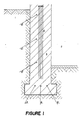
- la figure 1 est une vue en coupe de la partie basse d'un mur présentant une humidité ascendante;
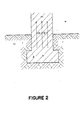
- la figure 2 est une vue en coupe de la partie basse d'un mur présentant une inversion de la polarité;
- la figure 3 est une vue en coupe de la partie basse du mur représentée à la figure 2, dans laquelle on introduit, moyennant un orifice, un tube, barre ou faisceau faisant partie d'un dispositif électronique pour la mise en oeuvre du procédé conforme à l'invention;
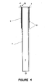
- la figure 4 est une vue en coupe du tube, barre ou faisceau représenté à la figure 3;
- la figure 5 est une vue synoptique d'un dispositif électronique pour la mise en oeuvre du procédé conforme à l'invention;
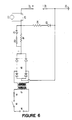
- la figure 6 est une vue schématique du circuit électronique faisant partie du dispositif électronique représenté à la figure 5;
- la figure 7 est une vue schématique du circuit électronique multivibrateur faisant partie du dispositif électronique pour la mise en oeuvre du procédé conforme à l'invention, dans le cas de murs très humides ou en contact direct avec une nappe d'eau, et
- la figure 8 est une vue synoptique du dispositif électronique conforme à l'invention, intégrant le circuit électronique multivibrateur représenté à la figure 7.
- Figure 1 is a sectional view of the lower part of a wall with rising humidity;
- Figure 2 is a sectional view of the lower part of a wall having a reverse polarity;
- Figure 3 is a sectional view of the part bottom of the wall shown in Figure 2, into which is introduced, through an orifice, a tube, bar or beam forming part of an electronic device for the implementation of the method according to the invention;
- Figure 4 is a sectional view of the tube, bar or bundle shown in Figure 3;
- Figure 5 is a block view of an electronic device for implementing the method according to the invention;
- Figure 6 is a schematic view of the electronic circuit forming part of the electronic device shown in Figure 5;
- FIG. 7 is a schematic view of the multivibrator electronic circuit forming part of the electronic device for implementing the method according to the invention, in the case of very damp walls or in direct contact with a sheet of water, and
- FIG. 8 is a block diagram of the electronic device according to the invention, integrating the multivibrator electronic circuit shown in FIG. 7.
Conformément à l'invention, le procédé de traitement de l'humidité ascendante dans les murs consiste, notamment, à forer préalablement au moins un orifice dans lesdits murs, à y introduire au moins un tube, barre ou faisceau métallique, ledit procédé étant caractérisé en ce qu'il comporte, principalement, deux phases distinctes de traitement, à savoir, d'une part, une phase d'apport d'énergie consistant, après avoir ajouté un élément de catalyse dans les orifices 6 en plus des barres, tubes ou faisceaux 7, à envoyer des impulsions électriques, fournies par un circuit électronique 12, sur lesdits tubes, barres ou faisceaux 7, réalisant ainsi, simultanément, d'une part, une accumulation de charges électrostatiques au niveau des barres, tubes ou faisceaux 7, et, d'autre part, grâce à un phénomène de résonance dudit circuit électronique 12 avec le circuit interne propre du mur 3, une polarisation au niveau de l'électrolyte intracapillaire du mur, aboutissant à un dépôt de sels silicocalciques insolubles sur les parois des capillaires des fondations, et à effectuer des mesures de contrôle du taux d'humidité 4 et, d'autre part, une phase électrostatique consistant, lorsque le degré d'assèchement souhaité du mur 3 est atteint, à déconnecter le circuit électronique 12, puis à boucher les orifices 6 de percement de manière à sceller les barres, tubes ou faisceaux 7, ainsi chargés, dans le mur 3, permettant ainsi à l'effet électrostatique des barres, tubes ou faisceaux 7 de se développer, et à l'assèchement du mur 3 de se poursuivre par l'élimination rapide de l'eau restante par les voies naturelles et par la suppression, à long terme, de l'effet de pompe électrique, du fait de l'élimination durable de l'inversion de polarité 5, responsable de l'ascension de l'humidité 4 dans les murs 3.In accordance with the invention, the method of treating rising humidity in the walls consists, in particular, in previously drilling at least one orifice in the said walls, in introducing at least one tube, bar or metallic beam therein, the said method being characterized in that it mainly comprises two distinct treatment phases, namely, on the one hand, an energy supply phase consisting, after having added a catalysis element in the
Comme le montrent les figures 5 et 8 des dessins annexés, le procédé, objet de l'invention, consiste, dans un premier temps, à implanter obliquement ou verticalement une série de barres, tubes ou faisceaux 7 dans un mur 3 à des distances calculées pour permettre le recouvrement des forces de champ, ces éléments 7 étant reliés au circuit électronique 12 générateur d'impulsions par l'intermédiaire d'une boîte d'alimentation 13 pendant la durée de la phase d'apport d'énergie, et déconnectés pendant la phase électrostatique.As shown in FIGS. 5 and 8 of the appended drawings, the process which is the subject of the invention consists, firstly, in implanting obliquely or vertically a series of bars, tubes or
Conformément à une autre caractéristique de l'invention, on introduit entre les barres, tubes ou faisceaux 7 et les parois des orifices 6 correspondants, forés dans le mur 3, un élément de catalyse pour la réaction physico-chimique intracapillaire d'obturation des pores, constitué par une poudre formée de cuivre métal en très fines particules, de zéolithe et d'oxylithe, si les conditions locales l'exigent.According to another characteristic of the invention, there is introduced between the bars, tubes or
Selon une autre caractéristique de l'invention, la phase électrostatique consiste principalement à déconnecter les barres, tubes ou faisceaux 7 du circuit électronique 12 et à maintenir à l'inversion des potentiels dans le mur 3, par l'action électrostatique des barres, tubes ou faisceaux 7.According to another characteristic of the invention, the electrostatic phase mainly consists in disconnecting the bars, tubes or
L'invention a également pour objet un dispositif électronique pour la mise en oeuvre du procédé, comportant des électrodes métalliques sous forme de barres, tubes ou faisceaux, introduites dans le mur à assécher, éventuellement scellées à l'aide de mortiers spécifiques, et reliées entre elles à l'extérieur du mur afin de former un circuit électrique fermé, caractérisé en ce que lesdits barres, tubes ou faisceaux sont reliés entre eux à l'extérieur du mur par l'intermédiaire d'un boîtier électronique 12 générateur d'impulsions et sont constitués, comme représenté à la figure 4 des dessins annexés, par un alliage ferrite, de nickel ou de lithium, ou par d'autres alliages tels que, notamment, fer-manganèse-zinc à gros cristaux, ou cuivre-zinc-arsenic, ou cuivre-nickel 10 Fe 1 Mn, ou encore cuivre-nickel 30 Fe 2 Mn2, lesdits tubes, barres ou faisceaux 7 étant recouverts du traitement de surface 11, d'un diélectrique 8, préférentiellement du PVC, et emmanchés, à leurs parties supérieures, chacun, dans un cylindre ou une bobine de fils de cuivre 9, qui sont isolés de façon partielle par une couche du même diélectrique 8, préférenteillement du PVC, lesdits tubes, barres ou faisceaux 7 faisant office de condensateurs, une fois insérés dans le mur 3.The invention also relates to an electronic device for implementing the method, comprising metal electrodes in the form of bars, tubes or bundles, introduced into the wall to be dried, possibly sealed using specific mortars, and connected together outside the wall to form a closed electrical circuit, characterized in that said bars, tubes or bundles are connected together outside the wall by means of an
Conformément à l'invention, et comme le montre la figure 6 des dessins annexés, le circuit électronique 12 comporte un transformateur 17 abaisseur de tension, relié au secteur par l'intermédiaire d'un interrupteur 15 et d'un fusible 16, alimentant un pont de diodes 18, dont une sortie est mise à la terre 26, et dont l'autre est branchée sur un circuit formé par trois résistances 19, 20, 24, dont l'une 19 constitue un régulateur d'intensité, ainsi que sur un shunt 25 et un ampèremètre de contrôle 22, deux diodes électroluminescentes 21,23 contrôlant l'équilibre dudit circuit électronique 12.According to the invention, and as shown in Figure 6 of the accompanying drawings, the
Selon une caractéristique de l'invention, le circuit électronique 12 génère des impulsions de polarité positive, sous un voltage variable, adapté aux conditions locales, et de 5 à 15 milli-ampères, à une fréquence de 100 Hertz pour un tube, barre ou faisceau 7, selon le jeu de diodes 18, chaque barre, tube ou faisceau 7 étant alimenté par l'intermédiaire d'une diode 29, montée en série.According to a characteristic of the invention, the
Conformément aux figures 4 et 5 des dessins annexés, la diode 29 est située à la partie supérieure de chaque barre, tube ou faisceau 7, pour équilibrer électriquement l'ensemble de l'installation du système, suivant l'évolution de la résistivité du mur 3 au cours de la phase d'apport d'énergie du procédé, l'alimentation se faisant en série.In accordance with Figures 4 and 5 of the accompanying drawings, the
Selon une caractéristique supplémentaire, et comme le montre la figure 8 des dessins annexés, le dispositif électronique pour la mise en oeuvre du procédé comporte, en outre, dans le cas de traitements de murs en contact direct avec l'eau, un circuit électronique 45 multivibrateur, représenté à la figure 7, réalisant un accord automatique avec le circuit interne propre au mur 3, suivant l'évolution des résistances et capacités de celui-ci au cours du temps, afin de maintenir l'état de résonance.According to an additional characteristic, and as shown in FIG. 8 of the accompanying drawings, the electronic device for implementing the method further comprises, in the case of treatments of walls in direct contact with water, an
L'étude des actions électrostatiques exercées à grande distance par und distribution de charges nous a donc conduits à utiliser pour les barres un dopage, de façon à obtenir des électrons faiblement liés.The study of the electrostatic actions exerted at great distance by a distribution of charges thus led us to use for the bars a doping, so as to obtain electrons weakly bonded.
Les alliages utilisés sont du type (non limitatif):
- -Ferrites de Nickel
- -Fer-Manganèse-Zinc en matériau à gros cristaux
- -Ferrites de Lithium
- -Cuivre-Zinc-Arsenic
- -Cuivre-
Nickel 10 Fe 1 Mn - -Cuivre-
Nickel 10Fe 2 Mn2
en barres pleines, en tubes ou en faisceaux. Barres d'alliages, tubes ou faisceaux ont subi un traitement de surface et sont recouverts d'un diélectrique qui est souvent du chlorure de Polyvi- nyle. La partie supérieure de la barre est insérée à l'intérieur d'un cylindre ou .d'une bobine de fil du même métal. Ce cylindre ou la bobine de fil sont partiellement recouverts du même diélectrique que la barre, et alimentés au travers d'une diode pour équilibrage.
- -Nickel Ferrites
- -Iron-Manganese-Zinc in large crystal material
- - Lithium Ferrites
- -Copper-Zinc-Arsenic
- -Copper-
Nickel 10 Fe 1 Mn - -Copper-
Nickel 10Fe 2 Mn2
in solid bars, tubes or bundles. Alloy bars, tubes or bundles have undergone a surface treatment and are covered with a dielectric which is often polyvinyl chloride. The upper part of the bar is inserted inside a cylinder or a coil of wire of the same metal. This cylinder or the coil of wire is partially covered with the same dielectric as the bar, and fed through a diode for balancing.
Il était nécessaire, dans le cas présent, de former ainsi un condensateur afin qu'une partie appréciable des forces de champ soit dirigée le long de la couche de diélectrique et non pas perpendiculairement à celle-ci, dans la partie supérieure de la barre.It was necessary, in the present case, to thus form a capacitor so that an appreciable part of the field forces is directed along the layer of dielectric and not perpendicular to this one, in the upper part of the bar.
La champ électromagnétique obtenu permet de mettre en oeuvre un important processus d'entraînement ionique, pour lequel le procédé comporte deux phases.The electromagnetic field obtained makes it possible to implement an important ionic drive process, for which the process comprises two phases.
Le principe est d'envoyer des impulsions sous un voltage variable, adapté aux conditions locales, de polarité positive, sous un ampérage de 5 à 15 milli-ampères (suivant les matériaux du mur) sous une fréquence de 100 Hertz.The principle is to send pulses under a variable voltage, adapted to local conditions, of positive polarity, under an amperage of 5 to 15 milli-amperes (depending on the materials of the wall) at a frequency of 100 Hertz.
Pour ce faire, on utilise un transformateur de 220 volts alimenté au travers d'un interrupteur et d'un fusible. Le secondaire est branché sur quatre diodes reliées d'une part à la terre et d'autre part à un circuit comprenant trois résistances R1, Rx et R2 et à un circuit pour un ampèremètre de contrôle. Rx constitue le régulateur d'intensité. Deux diodes électroluminescentes contrôlent l'équilibre du système.To do this, we use a 220-volt transformer supplied by a switch and a fuse. The secondary is connected to four diodes connected on the one hand to earth and on the other hand to a circuit comprising three resistors R1, Rx and R2 and to a circuit for a control ammeter. Rx constitutes the intensity regulator. Two light emitting diodes control the balance of the system.
L'ensemble de ces éléments constitue donc un circuit électronique generateur d'impulsions.All of these elements therefore constitute an electronic pulse generator circuit.
On sait qu'une polarisation est prévisible dans un système d'électrolytes en solution lorsqu'on est en mesure d'exercer, à l'aide d'un condensateur de capacité et d'une tension de charge suffisamment élevés, une "information directe". On peut obtenir ainsi une amorce de cristallisation à l'intérieur même des capillaires du mur.We know that a polarization is foreseeable in a system of electrolytes in solution when we are able to exert, using a capacitor of sufficiently high capacity and charge voltage, "direct information ". One can thus obtain a primer of crystallization inside the capillaries of the wall.
Dans le procédé cet effet est obtenu de la façon suivante: il est bien connu (Electrophysikalische Verfahren zur Mauertrockenlegung. Teil 1 que les murs se comportent, du point de vue électrique, comme un circuit Résistance-condensateur. Le dispositif situé à la partie supérieure des barres, (tubes ou faisceaux) se comporte comme un condensateur chargé par les impulsions à 100 Hz du circuit électronique générateur. Ce condensateur se décharge dans le circuit du mur, lequel a la propriété de varier en résistance et en capacité dans le temps, suivant l'état des électrolytes du mur.In the process this effect is obtained in the following way: it is well known (Electrophysikalische Verfahren zur Mauertrockenlegung. Teil 1 that the walls behave, from the electrical point of view, like a resistance-capacitor circuit. The device located at the top bars, (tubes or beams) behaves like a capacitor charged by the pulses at 100 Hz of the electronic generator circuit. This capacitor is discharged in the circuit of the wall, which has the property to vary in resistance and in capacity in time, depending on the condition of the electrolytes in the wall.
A différents moments de ces variations, les décharges en provenance de la barre vont se trouver en résonance (comme un résonateur de Oudin) avec le circuit du mur. On obtient ainsi une tension de charge élevée qui est à l'origine des phénomènes de polarisation et de cristallisation au niveau de l'électrolyte intracapillaire.At different times of these variations, the discharges from the bar will find themselves in resonance (like an Oudin resonator) with the circuit of the wall. A high charge voltage is thus obtained, which is the source of the polarization and crystallization phenomena at the level of the intracapillary electrolyte.
A début la décharge du condensateur est oscillatoire, car la résistance est faible et la self notable et nous sommes dans les conditions de la polarisation et de la cristallisation. Au bout de quelque temps nous sommes dans les conditions d'une décharge quasi-continue qui favorise, autour de l'amorce réalisée par le cristal, le dépôt de sels amorphes insolubles dans la formation desquels les ions cuivre libérés à partir de l'électrolyse partielle du cylindre (ou de la bobine) de cuivre, ou de l'électrolyse d'une poudre de cuivre en présence de zéolithe, jouent le rôle de catalyseur. La poudre est introduite dans l'orifice lors de la pose de la barre dans le mur.At the beginning the discharge of the capacitor is oscillatory, because the resistance is weak and the self notable and we are in the conditions of polarization and crystallization. At the end of some time we are in the conditions of a quasi-continuous discharge which favors, around the primer produced by the crystal, the deposition of insoluble amorphous salts in the formation of which the copper ions released from electrolysis partial of the copper cylinder (or coil), or of the electrolysis of a copper powder in the presence of zeolite, play the role of catalyst. The powder is introduced into the hole when the bar is placed in the wall.
La zéolithe active le catalyseur par le phénomène bien connu d'intercalation dans un silicate lamellaire. Si nécessaire ou ajoute de l'oxylithe pour fournir de l'oxygène naissant au contact de l'eau du mur pour éviter l'accumulation d'hydrogène en provenance des molécules d'eau qui auront subit l'électrolyse.The zeolite activates the catalyst by the well-known phenomenon of intercalation in a lamellar silicate. If necessary or add oxylithe to provide nascent oxygen on contact with the wall water to avoid the accumulation of hydrogen coming from the water molecules which will have undergone electrolysis.
On obtient ainsi l'obturation en quelques semaines de la majorité des pores capillaires du mur.Obtaining the obturation in a few weeks of the majority of the capillary pores of the wall.
Les murs en contact direct avec une nappe liquide (Venise, Florence, etc...) nécessitent un autre circuit électronique pour obtenir le ,résultat précité. Ce circuit supplémentaire est, par constitue un multivibrateur dont la fréquence et le rapport cyclique sont ajustés automatiquement après étalonnage de départ. Il est alimente sous un voltage, continu (Alimentation conventionnelle) et permet d'alimenter les barres sous une intensité de 5 mA à 1,5 A; il est ainsi complémentaire du circuit électronique générateur d'impulsions.Walls in direct contact with a liquid sheet (Venice, Florence, etc.) require another electronic circuit to obtain the above-mentioned result. This additional circuit is, by consti kills a multivibrator whose frequency and duty cycle are automatically adjusted after initial calibration. It is supplied with a continuous voltage (conventional power supply) and enables the bars to be supplied with an intensity of 5 mA to 1.5 A; it is thus complementary to the electronic pulse generator circuit.
Il constitue un oscillateur astable, qui permet de maintenir l'état de résonance avec le circuit propre du mur.It constitutes an astable oscillator, which makes it possible to maintain the state of resonance with the proper circuit of the wall.
La résistance de charge, ainsi que la "capacité parasite" offertes par le mur nous donnent le premier élément de l'oscillateur comme résistance de charge du transistor T2- Le transistor T1 verra sa charge ajustée par la résistance R1 de façon à rendre la forme d'onde de départ aussi symétrique que possible (rapport cyclique 50/50, sous forme rectangulaire).The load resistance, as well as the "parasitic capacity" offered by the wall give us the first element of the oscillator as the load resistance of the transistor T2- The transistor T1 will have its load adjusted by the resistance R1 so as to return the shape starting wave as symmetrical as possible (duty cycle 50/50, in rectangular form).
Les transistors T1 et T2 étant correctement polarisés par les résistances de base RG1 et RG2, il suffit de mettre en réaction l'oscillateur astable par les condensateurs C1 et C2. Le système rentre donc en oscillation accordée sur une fréquence déterminée à l'avence selon la résistivité sur le mur.The transistors T1 and T2 being correctly polarized by the basic resistors RG1 and RG2, it suffices to react the astable oscillator by the capacitors C1 and C2. The system therefore enters an oscillation tuned to a frequency determined by the aircraft according to the resistivity on the wall.
RL est la résistance de limitation de l'intensité de départ au début de l'assèchement et aussi suivant le nombre de barres, la capacité C 44 assure un découplage sur l'alimentation des transistors.RL is the resistance limiting the starting intensity at the start of the drying and also depending on the number of bars, the capacitance C 44 ensures decoupling on the supply of the transistors.
Le circuit LED est composé du condensateur C3, de la résistance R3 et de la diode D3, il sert seulement à visualiser que l'appareil oscille correctement. En effet, en l'absence d'oscillations le condensateur C3 n'est pas conducteur et, de ce fait, n'alimente pas la diode LED, R3 servant à limiter le courant dans la diode.The LED circuit consists of the capacitor C3, the resistor R3 and the diode D3, it is only used to visualize that the device is oscillating correctly. Indeed, in the absence of oscillations, the capacitor C3 is not conductive and, therefore, does not supply the LED diode, R3 serving to limit the current in the diode.
Que va-t-il se passer dans le temps ? Au fur et à mesure du traitement du mur, la résistance des barres (RX) et la capacité parasite (CX) des barres vont changer de valeur, c'est-à-dire que RX va voir ses valeurs augmenter et CX sa capacité diminuer. La constante de temps offerte par RX+C2 va changer, seule la constante de temps C1 ajustée avec R1 va rester constante. De ce fiat la fréquence de l'oscillateur va glisser vers des valeurs inférieures à celles du point de départ ainsi que le rapport cyclique qui va en diminuant dans les valeurs positives.What will happen in time? As the wall is treated, the resistance of the bars (RX) and the parasitic capacity (CX) of the bars will change in value, i.e. RX will see its values increase and CX its capacity will decrease . The time constant offered by RX + C2 will change, only the time constant C1 adjusted with R1 will remain constant. From this fiat the frequency of the oscillator will slide towards values lower than those of the starting point as well as the duty cycle which will decrease in the positive values.
En cas d'assèchement total avec une valeur très élevée de RX, l'oscillateur peut s'arrêter totalement.In the event of total drying with a very high value of RX, the oscillator can stop completely.
Ainsi est maintenu l'accord entre l'oscillateur astable et le circuit interne+capacité propre du mur, et cette résonnance continue permet de maintenir les tensions élevées nécessaires à un blocage rapide des capillaires dans les conditions difficiles rencontrées dans le mur près de la nappe d'eau, comme dans les murs anciens, épais et très humides. Un champ électrique d'intensité suffisante pour vaincre l'effet Schottky (qui tend à maintenir les électrons prisonniers du métal) permet ainsi la libération des électrons facilement mobilisables du métal. Ces électrons vont aller à la rencontre des valences de la solution d'électrolytes du mur et annuler les effets de la différence de potentiel primitive du mur.Thus is maintained the agreement between the astable oscillator and the internal circuit + own capacity of the wall, and this continuous resonance makes it possible to maintain the high voltages necessary for a rapid blocking of the capillaries in the difficult conditions encountered in the wall near the sheet. of water, as in old walls, thick and very humid. An electric field of sufficient intensity to overcome the Schottky effect (which tends to keep the electrons trapped in the metal) thus allows the release of the easily mobilizable electrons from the metal. These electrons will meet the valences of the electrolyte solution of the wall and cancel the effects of the difference in primitive potential of the wall.
Les impulsions envoyées permettent l'accumulation de charges électrostatiques dans le diélectrique des barres, produisant un fort mouvement des ions solvatés (donc de leur couronne de molécules d'eau dipolaires) vers les surfaces d'évaporation du mur. Il se crée également une inversion du courant ascendant à l'intérieur des capillaires par un phénomène identique. Ainsi un transport d'eau efficace qui accèlère l'assèchement du mur est mis en place.The pulses sent allow the accumulation of electrostatic charges in the dielectric of the bars, producing a strong movement of the solvated ions (therefore of their crown of dipolar water molecules) towards the evaporation surfaces of the wall. An inversion of the updraft inside the capillaries is also created by an identical phenomenon. Thus an efficient water transport which accelerates the drying of the wall is put in place.
Le procédé est maintenu sous tension suffisamment longtemps pour que l'assèchement devienne évident par les mesures de contrôle. Alors la source extérieure de courant est déconnectée. On passe alors à laThe process is kept energized long enough for drying to become evident through control measures. Then the external current source is disconnected. We then go to the
De façon passive, du fait de la structure des barres, une différence de potentiel s'établit, qui peut atteindre et dépasser 800 millivolts, et qui maintient l'inversion qui a permis de stopper l'ascension de l'eau.Passively, due to the structure of the bars, a potential difference is established, which can reach and exceed 800 millivolts, and which maintains the inversion which made it possible to stop the ascent of the water.
Toutefois celle phase passive du procédé est essentiellement liée à l'électrostatique. En effet, le frottement des ions en mouvement contre le diélectrique (PVC) crée une accumulation de charges statiques sur ce mainteau synthétique. Le traitement de surface maintient l'équilibre électrostatique du tube, barre on faisceau, et, de ce fait, les charges restent superficielles et s'accumulent sur le diélectrique. On obtient ainsi le champ électromagnétique maximum des barres, tubes ou faisceaux.However, this passive phase of the process is essentially linked to electrostatics. Indeed, the friction of the ions in movement against the dielectric (PVC) creates an accumulation of static charges on this synthetic maintenance. The surface treatment maintains the electrostatic balance of the tube, bar on beam, and, therefore, the charges remain superficial and accumulate on the dielectric. The maximum electromagnetic field of the bars, tubes or beams is thus obtained.
Les barres sont introduites dans les murs suivant des données précises calculées pour assurer un recouvrement efficace et sans lacunes de leur rayonnement radial. La procédé est susceptible de conserver son activité fort au-delà de la période décennale, les barres étant insensibles à l'électrolyse.The bars are introduced into the walls according to precise data calculated to ensure an efficient and gap-free recovery of their radial radiation. The process is likely to retain its strong activity beyond the ten-year period, the bars being insensitive to electrolysis.
Les explications seront mieux comprises en se référant aux dessins annexés.
- La figure 1 représente un mur 3 en coupe et le cheminement ascendant de l'humidité 4 à partir de sol 1 en suivant les flèches 4 vers la partie supérieure du mur au contact avec l'air ambiant 2.
- La figure 2 représente un mur 3 en coupe, implanté dans le sol 1 avec l'invention de la polarité 5 accélérant la montée des ions solvatés responsables du transport d'eau.
- La figure 3 représente un mur 3 en coupe avec
un trou 6 foré dans ce mur 3 implanté dans le sol 1. Dans ce trou 6 une barre (tube faisceau) 7 est partiellement engagée. - La figure 4 représente une barre (tube ou faisceau) 7 en coupe longitudinale montrant la partie métallique 7 recouverte du traitement ds surface 11, lui-même enveloppé d'une couche adhérente de diélectrique 8. La partie supérieure est introduite dans un cylindre de cuivre ou une bobine de fil de cuivre 9 calibrés pour être en contact du diélectrique 8 et, eux-mêmes partiellement recouverts du même diélectrique 8. Ce
cylindre ou bobine 9 est alimenté parl'intermédiaire d'une diode 29 et d'un fil deliaison 10. - La figure 5 représente le schéma d'implantation des barres (tubes ou faisceaux) 7 dans un mur vu de face. Dans des
orifices 6 forés dans ce mur 3 en direction oblique ou verticale jusqu'aux fondations les barres (tubes ou faisceaux) 7 sont introduites. Les cylindres (ou bobines) 9 sont connectés à desdiodes 29 et par des fils conducteurs 10 à une boîte deliaison 13, elle-même reliée électriquement au circuit électronique 12 générateur d'impulsions. - La figure 6 représente le schéma du circuit électronique 12 générateur d'impulsions.
Ce circuit 12 est alimenté à partir du secteur 220volts 14, au travers d'un interrupteur 15 et d'un fusible 16, par le primaire du transformateur 17. Le secondaire du transformateur 17 est branché sur quatrediodes 18 reliées, d'une part, à laterre 26 et, d'autre part, à un circuit comprenant trois résistances 19, 20 et 24, et à un circuit constitué d'un shunt 25 et d'un ampèremètre de contrôle 22. La résistance 19 constitue un régulateur d'intensité.Deux diodes 21 et 23 électroluminescentes contrôlent le mise sous tension et évitent une éventuelle surcharge. L'intensité est limitée à 100 Ohms, 10 watts. Le circuit est doté d'une sortie positive 27et négative 28.
- FIG. 1 represents a
wall 3 in section and the upward path of humidity 4 from ground 1 by following the arrows 4 towards the upper part of the wall in contact with theambient air 2. - FIG. 2 represents a
wall 3 in section, implanted in the ground 1 with the invention of polarity 5 accelerating the rise of the solvated ions responsible for the transport of water. - FIG. 3 represents a
wall 3 in section with ahole 6 drilled in thiswall 3 implanted in the ground 1. In this hole 6 a bar (beam tube) 7 is partially engaged. - FIG. 4 represents a bar (tube or bundle) 7 in longitudinal section showing the
metal part 7 covered with the surface treatment 11, itself wrapped in an adhesive layer ofdielectric 8. The upper part is introduced into a copper cylinder or a coil ofcopper wire 9 calibrated to be in contact with the dielectric 8 and, themselves partial ment covered with thesame dielectric 8. This cylinder orcoil 9 is supplied via adiode 29 and a connectingwire 10. - FIG. 5 represents the layout diagram of the bars (tubes or bundles) 7 in a wall seen from the front. In holes 6 drilled in this
wall 3 in an oblique or vertical direction to the foundations, the bars (tubes or bundles) 7 are introduced. The cylinders (or coils) 9 are connected todiodes 29 and byconductive wires 10 to aconnection box 13, itself electrically connected to theelectronic circuit 12 pulse generator. - FIG. 6 represents the diagram of the
electronic circuit 12 pulse generator. Thiscircuit 12 is supplied from the 220volt sector 14, through aswitch 15 and afuse 16, by the primary of thetransformer 17. The secondary of thetransformer 17 is connected to fourdiodes 18 connected, of a firstly, toearth 26 and, secondly, to a circuit comprising threeresistors 19, 20 and 24, and to a circuit consisting of ashunt 25 and acontrol ammeter 22. The resistor 19 constitutes a regulator intensity. Two light-emittingdiodes 21 and 23 control power-up and prevent possible overload. The intensity is limited to 100 Ohms, 10 watts. The circuit has a positive 27 and negative 28 output.
Les impulsions de sorties sont d'un voltage variable, adapté aux circonstances locales, et à 5 à 15 milliampères par barre 7.The output pulses are of variable voltage, adapted to local circumstances, and at 5 to 15 milliamps per
La forme des ondes de sortie est en dents de scie à une fréquence de 100 Hertz.The shape of the output waves is jagged at a frequency of 100 Hertz.
La figure 7 représente la constitution du circuit électronique 45 multivibrateur, jouant le rôle d'un oscillateur astable décrit par ailleurs:
- 30: alimentation à partir du circuit décrit dans la figure 6
- 31: T1 Transistor
- 32: T2 Transistor
- 33: Condensateur C1
- 34; Condensateur C2
- 35: Résistance R1 ajustable
- 36: Résistance Rb 1
- 37:
Résistance Rb 2 - 38: Résistance des barres
- 39: Condensateur CX des barres
- 40: Condensateur C3
- 41: Diode D3 rouge de contrôle
- 42: Résistance R3
- 43: Résistance de limitation RL
- 44: Capacité
- 30: power supply from the circuit described in figure 6
- 31: T1 Transistor
- 32: T2 Transistor
- 33: Capacitor C1
- 34; C2 capacitor
- 35: Adjustable resistance R1
- 36: Resistance Rb 1
- 37:
Resistance Rb 2 - 38: Bar resistance
- 39: CX busbar capacitor
- 40: Capacitor C3
- 41: Red D3 control diode
- 42: Resistor R3
- 43: Limiting resistance RL
- 44: Capacity
La figure 8 représente le schéma d'implantation des barres (ou tubes ou faisceaux) alimentés par l'intermédiaire du circuit électronique 45 complémentaire, à fonction de multivibrateur, pour le traitement des murs 3 très humides ou en contact direct avec une nappe d'eau:
- 1: Sol
- 3: Mur
- 6: Trous forés dans les murs
- 7: Barres, tubes ou faisceaux
- 9: Cylindres ou bobines
- 10: Fils de liaison
- 12: Circuit électronique générateur d'impulsions
- 13: Boîte de liaison
- 29: Diodes
- 45: Multivibrateur électronique alimenté directement par le circuit électronique 12 générateur d'impulsions 12 et réalisant l'état de résonance avec le circuit interne du mur 3.
- 1: Floor
- 3: Wall
- 6: Holes drilled in the walls
- 7: Bars, tubes or bundles
- 9: Cylinders or coils
- 10: Connecting wires
- 12: Electronic pulse generator circuit
- 13: Connection box
- 29: Diodes
- 45: Electronic multivibrator supplied directly by the
electronic circuit 12pulse generator 12 and achieving the state of resonance with the internal circuit of thewall 3.
Bien entendu, l'invention n'est pas limitée au mode de réalisation décrit et représenté aux dessins annexés. Des modifications restent possibles, notamment du point de vue de la constitution des divers éléments ou par substitution d'équivalents techniques, sans sortir pour autant du domaine de protection de l'invention, tel que défini par les revendications.Of course, the invention is not limited to the embodiment described and shown in the accompanying drawings. Modifications remain possible, in particular from the point of view of the constitution of the various elements or by substitution of technical equivalents, without thereby departing from the scope of protection of the invention, as defined by the claims.
Claims (9)
Applications Claiming Priority (4)
| Application Number | Priority Date | Filing Date | Title |
|---|---|---|---|
| FR8517051 | 1985-11-19 | ||
| FR8517051A FR2590296B1 (en) | 1985-11-19 | 1985-11-19 | METHOD FOR TREATING ASCENDING MOISTURE IN WALLS AND DEVICE FOR IMPLEMENTING SAME |
| FR8519573 | 1985-12-27 | ||
| FR8519573A FR2592415B1 (en) | 1985-12-27 | 1985-12-27 | PROCESS FOR DEWATERING THE ASCENDING MOISTURE OF WALLS AND DEVICE FOR IMPLEMENTING SAME |
Publications (2)
| Publication Number | Publication Date |
|---|---|
| EP0245416A1 EP0245416A1 (en) | 1987-11-19 |
| EP0245416B1 true EP0245416B1 (en) | 1990-10-10 |
Family
ID=26224828
Family Applications (1)
| Application Number | Title | Priority Date | Filing Date |
|---|---|---|---|
| EP19860906845 Expired - Lifetime EP0245416B1 (en) | 1985-11-19 | 1986-11-18 | Method for treating ascending dampness in walls and electronical device for carrying out this method |
Country Status (3)
| Country | Link |
|---|---|
| EP (1) | EP0245416B1 (en) |
| DE (1) | DE3674921D1 (en) |
| WO (1) | WO1987003030A1 (en) |
Families Citing this family (2)
| Publication number | Priority date | Publication date | Assignee | Title |
|---|---|---|---|---|
| NO891034L (en) * | 1989-03-10 | 1990-09-11 | Elcraft As | PROCEDURE AND APPARATUS FOR MANAGING RELATIVE MOISTURE IN CONCRETE AND WALL CONSTRUCTIONS. |
| FR2754076A1 (en) * | 1996-10-01 | 1998-04-03 | Mastchenko Alain Michel | Method for control and regulation of the hydrometric rate of a chosen medium under the action of an electric current. |
Family Cites Families (5)
| Publication number | Priority date | Publication date | Assignee | Title |
|---|---|---|---|---|
| US3523884A (en) * | 1968-05-10 | 1970-08-11 | Systron Donner Corp | Method and apparatus for making wall structure impervious to moisture |
| GB1277237A (en) * | 1969-06-17 | 1972-06-07 | Damplast Ltd | Moisture control |
| FR2365666A1 (en) * | 1976-09-28 | 1978-04-21 | Delbecq Germaine | Automatic electronic system for drying out buildings - counteracts natural electric current caused by dampness |
| US4180953A (en) * | 1976-12-17 | 1980-01-01 | Constantin Mihaescu | Method and apparatus for countering an upward capillary flow of soil moisture in a foundation wall |
| GB1593650A (en) * | 1978-05-02 | 1981-07-22 | Newbery E M | Assembly of anodes for use in an electro-osmotic damp proofing system |
-
1986
- 1986-11-18 WO PCT/FR1986/000389 patent/WO1987003030A1/en active IP Right Grant
- 1986-11-18 EP EP19860906845 patent/EP0245416B1/en not_active Expired - Lifetime
- 1986-11-18 DE DE8686906845T patent/DE3674921D1/en not_active Expired - Fee Related
Also Published As
| Publication number | Publication date |
|---|---|
| DE3674921D1 (en) | 1990-11-15 |
| EP0245416A1 (en) | 1987-11-19 |
| WO1987003030A1 (en) | 1987-05-21 |
Similar Documents
| Publication | Publication Date | Title |
|---|---|---|
| Kim et al. | Nociceptive memristor | |
| Goldman et al. | Corona discharges | |
| Schoenbach et al. | Intracellular effect of ultrashort electrical pulses | |
| Cherifi et al. | The validation of the thermal step method | |
| CA1245710A (en) | Lightning rod with intermittent pulsed corona discharge | |
| EP3146204B1 (en) | Device for forming a quasi-neutral beam of oppositely charged particles | |
| JP2007250557A5 (en) | ||
| KR920009272A (en) | Ion Implantation Apparatus and Method | |
| EP0245416B1 (en) | Method for treating ascending dampness in walls and electronical device for carrying out this method | |
| Lambe | Recombination processes in cadmium sulfide | |
| Sjöström et al. | Miniaturized ionic polarization diodes for neurotransmitter release at synaptic speeds | |
| Cogan et al. | The effect of electrode geometry on electrochemical properties measured in saline | |
| FR2583579A1 (en) | PROCESS FOR OBTAINING PIEZOELECTRIC MATERIAL AND DEVICE FOR IMPLEMENTING THE SAME | |
| EP0064003B1 (en) | Device for the pulsed electron beam processing of a specimen | |
| FR2612276A1 (en) | Bistable electromagnetic inductor methods and devices for solenoid valves and connected electrical circuits, with very low electrical consumption; with application to automatic watering controlled by the water requirements of the plants at the desired depth | |
| FR2624319A1 (en) | ION EMISSION LIGHTNING PROTECTION DEVICES | |
| FR2752344A1 (en) | HIGH VOLTAGE CURRENT PULSES GENERATION CIRCUIT DELIVERED IN A CHARGING CIRCUIT AND IMPLEMENTATION PROCEDURE | |
| Durney et al. | Investigation of AC‐DC magnetic field effects in planar phospholipid bilayers | |
| EP0766649A1 (en) | Method and device for generating low voltage electric fields in aqueous solutions | |
| EP1230947A1 (en) | Active implantable medical device, in particular pacemaker, defibrillator and/or cardioverter or multisite device, with beat-to-beat capture assay | |
| EP0494012B1 (en) | Method and device for checking the electrically insulating state of an electrically conducting construction | |
| FR2973886A1 (en) | Method for determining leakage path formed in portion of e.g. lake embankment anchored in soil, involves determining equipotential curves on map of wall portion, and determining leakage path based on equipotential curves | |
| EP0035447B1 (en) | Process and apparatus for the treatment of textile threads or fibres | |
| CS204128B1 (en) | Method of electrostatic coating the workpieces by the powdery coating substances in the fluid bed and facility for making same | |
| Misurkin et al. | A method for the generation of solvated electrons in polar solvents |
Legal Events
| Date | Code | Title | Description |
|---|---|---|---|
| PUAI | Public reference made under article 153(3) epc to a published international application that has entered the european phase |
Free format text: ORIGINAL CODE: 0009012 |
|
| 17P | Request for examination filed |
Effective date: 19870715 |
|
| AK | Designated contracting states |
Kind code of ref document: A1 Designated state(s): CH DE GB IT LI |
|
| 17Q | First examination report despatched |
Effective date: 19881214 |
|
| RAP3 | Party data changed (applicant data changed or rights of an application transferred) |
Owner name: ALLOY, ANDRE YVES JULES |
|
| GRAA | (expected) grant |
Free format text: ORIGINAL CODE: 0009210 |
|
| AK | Designated contracting states |
Kind code of ref document: B1 Designated state(s): CH DE GB IT LI |
|
| PG25 | Lapsed in a contracting state [announced via postgrant information from national office to epo] |
Ref country code: IT Free format text: LAPSE BECAUSE OF FAILURE TO SUBMIT A TRANSLATION OF THE DESCRIPTION OR TO PAY THE FEE WITHIN THE PRE;WARNING: LAPSES OF ITALIAN PATENTS WITH EFFECTIVE DATE BEFORE 2007 MAY HAVE OCCURRED AT ANY TIME BEFORE 2007. THE CORRECT EFFECTIVE DATE MAY BE DIFFERENT FROM THE ONE RECORDED.SCRIBED TIME-LIMIT Effective date: 19901010 Ref country code: GB Effective date: 19901010 |
|
| REF | Corresponds to: |
Ref document number: 3674921 Country of ref document: DE Date of ref document: 19901115 |
|
| GBV | Gb: ep patent (uk) treated as always having been void in accordance with gb section 77(7)/1977 [no translation filed] | ||
| PLBE | No opposition filed within time limit |
Free format text: ORIGINAL CODE: 0009261 |
|
| STAA | Information on the status of an ep patent application or granted ep patent |
Free format text: STATUS: NO OPPOSITION FILED WITHIN TIME LIMIT |
|
| 26N | No opposition filed | ||
| REG | Reference to a national code |
Ref country code: CH Ref legal event code: PL |
|
| REG | Reference to a national code |
Ref country code: CH Ref legal event code: AEN Free format text: LE BREVET A ETE REACTIVE SELON LA DEMANDE DE POURSUITE DU 22.08.1997 |
|
| PGFP | Annual fee paid to national office [announced via postgrant information from national office to epo] |
Ref country code: CH Payment date: 19980602 Year of fee payment: 12 |
|
| PGFP | Annual fee paid to national office [announced via postgrant information from national office to epo] |
Ref country code: DE Payment date: 19980727 Year of fee payment: 12 |
|
| PG25 | Lapsed in a contracting state [announced via postgrant information from national office to epo] |
Ref country code: LI Free format text: LAPSE BECAUSE OF NON-PAYMENT OF DUE FEES Effective date: 19981130 Ref country code: CH Free format text: LAPSE BECAUSE OF NON-PAYMENT OF DUE FEES Effective date: 19981130 |
|
| REG | Reference to a national code |
Ref country code: CH Ref legal event code: PUE Owner name: ANDRE YVES JULES ALLOY TRANSFER- PIERRE BONECHER |
|
| REG | Reference to a national code |
Ref country code: CH Ref legal event code: PL |
|
| PG25 | Lapsed in a contracting state [announced via postgrant information from national office to epo] |
Ref country code: DE Free format text: LAPSE BECAUSE OF NON-PAYMENT OF DUE FEES Effective date: 19991103 |