EP0245416B1 - Behandlungsverfahren für aufsteigende feuchtigkeit in mauern und ausrichtung zur durchfuehrung desselben - Google Patents
Behandlungsverfahren für aufsteigende feuchtigkeit in mauern und ausrichtung zur durchfuehrung desselben Download PDFInfo
- Publication number
- EP0245416B1 EP0245416B1 EP19860906845 EP86906845A EP0245416B1 EP 0245416 B1 EP0245416 B1 EP 0245416B1 EP 19860906845 EP19860906845 EP 19860906845 EP 86906845 A EP86906845 A EP 86906845A EP 0245416 B1 EP0245416 B1 EP 0245416B1
- Authority
- EP
- European Patent Office
- Prior art keywords
- wall
- tubes
- bundles
- rods
- circuit
- Prior art date
- Legal status (The legal status is an assumption and is not a legal conclusion. Google has not performed a legal analysis and makes no representation as to the accuracy of the status listed.)
- Expired - Lifetime
Links
- 238000000034 method Methods 0.000 title claims abstract description 35
- 230000001174 ascending effect Effects 0.000 title 1
- 230000000694 effects Effects 0.000 claims abstract description 15
- 239000003792 electrolyte Substances 0.000 claims abstract description 7
- 238000006555 catalytic reaction Methods 0.000 claims abstract description 6
- 238000006243 chemical reaction Methods 0.000 claims abstract description 4
- XLYOFNOQVPJJNP-UHFFFAOYSA-N water Substances O XLYOFNOQVPJJNP-UHFFFAOYSA-N 0.000 claims description 17
- 239000003990 capacitor Substances 0.000 claims description 15
- RYGMFSIKBFXOCR-UHFFFAOYSA-N Copper Chemical compound [Cu] RYGMFSIKBFXOCR-UHFFFAOYSA-N 0.000 claims description 13
- PXHVJJICTQNCMI-UHFFFAOYSA-N Nickel Chemical compound [Ni] PXHVJJICTQNCMI-UHFFFAOYSA-N 0.000 claims description 13
- 238000001035 drying Methods 0.000 claims description 11
- XEEYBQQBJWHFJM-UHFFFAOYSA-N Iron Chemical compound [Fe] XEEYBQQBJWHFJM-UHFFFAOYSA-N 0.000 claims description 10
- 229910052802 copper Inorganic materials 0.000 claims description 9
- 239000010949 copper Substances 0.000 claims description 9
- 229910052751 metal Inorganic materials 0.000 claims description 9
- 239000002184 metal Substances 0.000 claims description 9
- 230000008030 elimination Effects 0.000 claims description 8
- 238000003379 elimination reaction Methods 0.000 claims description 8
- 229910052759 nickel Inorganic materials 0.000 claims description 7
- 230000000630 rising effect Effects 0.000 claims description 7
- 238000011282 treatment Methods 0.000 claims description 7
- 238000009825 accumulation Methods 0.000 claims description 6
- 229910045601 alloy Inorganic materials 0.000 claims description 5
- 239000000956 alloy Substances 0.000 claims description 5
- 238000004381 surface treatment Methods 0.000 claims description 5
- 229910021536 Zeolite Inorganic materials 0.000 claims description 4
- 239000013078 crystal Substances 0.000 claims description 4
- HNPSIPDUKPIQMN-UHFFFAOYSA-N dioxosilane;oxo(oxoalumanyloxy)alumane Chemical compound O=[Si]=O.O=[Al]O[Al]=O HNPSIPDUKPIQMN-UHFFFAOYSA-N 0.000 claims description 4
- 238000005553 drilling Methods 0.000 claims description 4
- 230000007774 longterm Effects 0.000 claims description 4
- 239000000843 powder Substances 0.000 claims description 4
- 239000010457 zeolite Substances 0.000 claims description 4
- 229910052785 arsenic Inorganic materials 0.000 claims description 3
- 239000004570 mortar (masonry) Substances 0.000 claims description 3
- 239000011701 zinc Substances 0.000 claims description 3
- 229910052725 zinc Inorganic materials 0.000 claims description 3
- 230000000903 blocking effect Effects 0.000 claims description 2
- 239000010419 fine particle Substances 0.000 claims description 2
- 238000009434 installation Methods 0.000 claims description 2
- 230000001629 suppression Effects 0.000 claims description 2
- HCHKCACWOHOZIP-UHFFFAOYSA-N Zinc Chemical compound [Zn] HCHKCACWOHOZIP-UHFFFAOYSA-N 0.000 claims 2
- 239000011572 manganese Substances 0.000 claims 2
- PWHULOQIROXLJO-UHFFFAOYSA-N Manganese Chemical compound [Mn] PWHULOQIROXLJO-UHFFFAOYSA-N 0.000 claims 1
- 229910052742 iron Inorganic materials 0.000 claims 1
- JXGGISJJMPYXGJ-UHFFFAOYSA-N lithium;oxido(oxo)iron Chemical compound [Li+].[O-][Fe]=O JXGGISJJMPYXGJ-UHFFFAOYSA-N 0.000 claims 1
- 229910052748 manganese Inorganic materials 0.000 claims 1
- KKCBUQHMOMHUOY-UHFFFAOYSA-N sodium oxide Chemical compound [O-2].[Na+].[Na+] KKCBUQHMOMHUOY-UHFFFAOYSA-N 0.000 claims 1
- 229910001948 sodium oxide Inorganic materials 0.000 claims 1
- 239000000126 substance Substances 0.000 claims 1
- 150000002500 ions Chemical class 0.000 abstract description 5
- JPVYNHNXODAKFH-UHFFFAOYSA-N Cu2+ Chemical compound [Cu+2] JPVYNHNXODAKFH-UHFFFAOYSA-N 0.000 abstract description 2
- 229910001431 copper ion Inorganic materials 0.000 abstract description 2
- 230000008020 evaporation Effects 0.000 abstract description 2
- 238000001704 evaporation Methods 0.000 abstract description 2
- 238000009830 intercalation Methods 0.000 abstract description 2
- 230000002687 intercalation Effects 0.000 abstract description 2
- 239000011248 coating agent Substances 0.000 abstract 1
- 238000000576 coating method Methods 0.000 abstract 1
- 230000001939 inductive effect Effects 0.000 abstract 1
- 150000004760 silicates Chemical class 0.000 abstract 1
- 239000012453 solvate Substances 0.000 abstract 1
- 238000005868 electrolysis reaction Methods 0.000 description 5
- 230000010287 polarization Effects 0.000 description 5
- 229910000859 α-Fe Inorganic materials 0.000 description 5
- 229910000570 Cupronickel Inorganic materials 0.000 description 4
- 238000010586 diagram Methods 0.000 description 4
- 229920000915 polyvinyl chloride Polymers 0.000 description 4
- 239000004800 polyvinyl chloride Substances 0.000 description 4
- 230000002441 reversible effect Effects 0.000 description 4
- 101100203596 Caenorhabditis elegans sol-1 gene Proteins 0.000 description 3
- 238000002425 crystallisation Methods 0.000 description 3
- 230000008025 crystallization Effects 0.000 description 3
- 239000003054 catalyst Substances 0.000 description 2
- 230000000295 complement effect Effects 0.000 description 2
- YOCUPQPZWBBYIX-UHFFFAOYSA-N copper nickel Chemical compound [Ni].[Cu] YOCUPQPZWBBYIX-UHFFFAOYSA-N 0.000 description 2
- 238000000151 deposition Methods 0.000 description 2
- 230000005672 electromagnetic field Effects 0.000 description 2
- 230000002045 lasting effect Effects 0.000 description 2
- 239000010410 layer Substances 0.000 description 2
- 229910052744 lithium Inorganic materials 0.000 description 2
- 239000000463 material Substances 0.000 description 2
- 238000005259 measurement Methods 0.000 description 2
- 230000010355 oscillation Effects 0.000 description 2
- 230000003071 parasitic effect Effects 0.000 description 2
- 239000011148 porous material Substances 0.000 description 2
- 239000003566 sealing material Substances 0.000 description 2
- 239000000243 solution Substances 0.000 description 2
- UFHFLCQGNIYNRP-UHFFFAOYSA-N Hydrogen Chemical compound [H][H] UFHFLCQGNIYNRP-UHFFFAOYSA-N 0.000 description 1
- 229910000733 Li alloy Inorganic materials 0.000 description 1
- WHXSMMKQMYFTQS-UHFFFAOYSA-N Lithium Chemical compound [Li] WHXSMMKQMYFTQS-UHFFFAOYSA-N 0.000 description 1
- 229910000990 Ni alloy Inorganic materials 0.000 description 1
- BPQQTUXANYXVAA-UHFFFAOYSA-N Orthosilicate Chemical compound [O-][Si]([O-])([O-])[O-] BPQQTUXANYXVAA-UHFFFAOYSA-N 0.000 description 1
- 229910000831 Steel Inorganic materials 0.000 description 1
- HFPUDQMSWREXAL-UHFFFAOYSA-N [Cu].[Zn].[As] Chemical compound [Cu].[Zn].[As] HFPUDQMSWREXAL-UHFFFAOYSA-N 0.000 description 1
- LNRYQGINUXUWLV-UHFFFAOYSA-N [Mn].[Fe].[Zn] Chemical compound [Mn].[Fe].[Zn] LNRYQGINUXUWLV-UHFFFAOYSA-N 0.000 description 1
- 239000012790 adhesive layer Substances 0.000 description 1
- 239000003570 air Substances 0.000 description 1
- 239000012080 ambient air Substances 0.000 description 1
- 230000000712 assembly Effects 0.000 description 1
- 238000000429 assembly Methods 0.000 description 1
- QVGXLLKOCUKJST-UHFFFAOYSA-N atomic oxygen Chemical compound [O] QVGXLLKOCUKJST-UHFFFAOYSA-N 0.000 description 1
- 230000015572 biosynthetic process Effects 0.000 description 1
- 238000010276 construction Methods 0.000 description 1
- 230000008021 deposition Effects 0.000 description 1
- -1 des ions Chemical class 0.000 description 1
- 238000004090 dissolution Methods 0.000 description 1
- 230000005684 electric field Effects 0.000 description 1
- 238000002848 electrochemical method Methods 0.000 description 1
- 239000008151 electrolyte solution Substances 0.000 description 1
- 239000001257 hydrogen Substances 0.000 description 1
- 229910052739 hydrogen Inorganic materials 0.000 description 1
- 238000002513 implantation Methods 0.000 description 1
- JEIPFZHSYJVQDO-UHFFFAOYSA-N iron(III) oxide Inorganic materials O=[Fe]O[Fe]=O JEIPFZHSYJVQDO-UHFFFAOYSA-N 0.000 description 1
- 239000007788 liquid Substances 0.000 description 1
- 239000001989 lithium alloy Substances 0.000 description 1
- 238000012423 maintenance Methods 0.000 description 1
- 230000014759 maintenance of location Effects 0.000 description 1
- 238000012986 modification Methods 0.000 description 1
- 230000004048 modification Effects 0.000 description 1
- 230000003534 oscillatory effect Effects 0.000 description 1
- 230000001590 oxidative effect Effects 0.000 description 1
- 239000001301 oxygen Substances 0.000 description 1
- 229910052760 oxygen Inorganic materials 0.000 description 1
- 230000005855 radiation Effects 0.000 description 1
- 238000011084 recovery Methods 0.000 description 1
- 150000003839 salts Chemical class 0.000 description 1
- 239000007787 solid Substances 0.000 description 1
- 230000003068 static effect Effects 0.000 description 1
- 239000010959 steel Substances 0.000 description 1
- 238000006467 substitution reaction Methods 0.000 description 1
Images


Classifications
-
- E—FIXED CONSTRUCTIONS
- E04—BUILDING
- E04B—GENERAL BUILDING CONSTRUCTIONS; WALLS, e.g. PARTITIONS; ROOFS; FLOORS; CEILINGS; INSULATION OR OTHER PROTECTION OF BUILDINGS
- E04B1/00—Constructions in general; Structures which are not restricted either to walls, e.g. partitions, or floors or ceilings or roofs
- E04B1/62—Insulation or other protection; Elements or use of specified material therefor
- E04B1/70—Drying or keeping dry, e.g. by air vents
- E04B1/7007—Drying or keeping dry, e.g. by air vents by using electricity, e.g. electro-osmosis
Definitions
- the present invention relates to a method of treating rising humidity in walls, as well as an electronic device for the implementation of this method.
- the present invention aims to interrupt this stack effect and, thereby, the rise of humidity in the walls by reversing the potential differences and closing the capillaries of the wall.
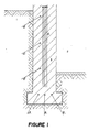
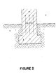
- holes or grooves are made in the walls, into which are introduced assemblies in the form of bars, tubes or metal beams.
- any conductive body brought into contact with the ground is negatively charged.
- electrochemical methods are used, based on the treatment of the rising humidity of a wall by the passage of a direct current using metallic electrodes in the form bars, tubes or bundles, introduced into the wall, and possibly sealed using specific mortars, aiming either to cancel or even to reverse the potential difference existing in the wall, and thus the current of responsible solvated ions water transport, or to seal the capillaries using a sealing material in the form of powder, the grains of which are diffused in the wall.
- the metal electrodes are then connected to the outside of the wall in order to form a closed electrical circuit, the wall constituting a part of this electrical circuit.
- the user in the case of the potential reversal in the wall, the user must continually supply energy to maintain the process. This involves considerable expenditure.
- the cancellation or inversion of potential necessarily leads either to the dissolution of one of the two electrodes by electrolysis, or to a deposit of insulating oxides on the two electrodes and therefore to an interruption of the process.
- the problem posed by the present invention therefore consists in devising a method for treating the rising humidity in the walls using electrodes, in the form of bars, tubes or bundles, introduced into orifices formed in said walls, simultaneously realizing, on the one hand, the rapid obturation of the capillaries of said walls and, on the other hand, the elimination, in the long term, of the electric pump effect, mainly responsible for the rise of humidity in the walls, without having to continually supply energy and without the electrodes oxidizing or disintegrating, and without moisture accumulating in the foundations, so as to result in a lasting drying of said walls.
- the method of treating rising humidity in the walls consists, in particular, in previously drilling at least one orifice in the said walls, in introducing at least one tube, bar or metallic beam therein, the said method being characterized in that it mainly comprises two distinct treatment phases, namely, on the one hand, an energy supply phase consisting, after having added a catalysis element in the orifices 6 in addition to the bars, tubes or beams 7, to send electrical pulses, supplied by an electronic circuit 12, onto said tubes, bars or beams 7, thus simultaneously producing, on the one hand, an accumulation of electrostatic charges at the level of bars, tubes or beams 7 , and, on the other hand, thanks to a phenomenon of resonance of said electronic circuit 12 with the proper internal circuit of the wall 3, a polarization at the level of the intracapillary electrolyte of the wall, resulting t depositing insoluble silico-calcium salts on the walls of the capillaries of the foundations, and carrying out measurements to control the humidity level 4 and, on the other hand
- the process which is the subject of the invention consists, firstly, in implanting obliquely or vertically a series of bars, tubes or bundles 7 in a wall 3 at calculated distances to allow field forces to be recovered, these elements 7 being connected to the electronic circuit 12 pulse generator via a power supply box 13 for the duration of the energy supply phase, and disconnected during the electrostatic phase.
- a catalysis element for the intracapillary physico-chemical reaction for closing the pores consisting of a powder formed from copper metal in very fine particles, zeolite and oxylith, if local conditions require it.
- the electrostatic phase mainly consists in disconnecting the bars, tubes or bundles 7 from the electronic circuit 12 and in maintaining the potentials in the wall 3 by the electrostatic action of the bars, tubes. or bundles 7.
- the invention also relates to an electronic device for implementing the method, comprising metal electrodes in the form of bars, tubes or bundles, introduced into the wall to be dried, possibly sealed using specific mortars, and connected together outside the wall to form a closed electrical circuit, characterized in that said bars, tubes or bundles are connected together outside the wall by means of an electronic generator 12 pulse generator and are constituted, as shown in FIG.
- the electronic circuit 12 comprises a step-down transformer 17, connected to the mains by means of a switch 15 and a fuse 16, supplying a diode bridge 18, one output of which is earthed 26, and the other of which is connected to a circuit formed by three resistors 19, 20, 24, one of which 19 constitutes an intensity regulator, as well as a shunt 25 and a control ammeter 22, two light-emitting diodes 21, 23 controlling the balance of said electronic circuit 12.
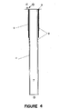
- the electronic circuit 12 generates pulses of positive polarity, at a variable voltage, suitable under local conditions, and from 5 to 15 milli-amperes, at a frequency of 100 Hertz for a tube, bar or beam 7, depending on the set of diodes 18, each bar, tube or beam 7 being supplied via a diode 29, connected in series.
- the diode 29 is located at the top of each bar, tube or bundle 7, to electrically balance the entire installation of the system, according to the evolution of the resistivity of the wall 3 during the energy supply phase of the process, the supply taking place in series.
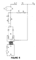
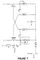
- the electronic device for implementing the method further comprises, in the case of treatments of walls in direct contact with water, an electronic circuit 45 multivibrator, represented in FIG. 7, performing an automatic tuning with the internal circuit specific to the wall 3, according to the evolution of the resistances and capacities of the latter over time, in order to maintain the state of resonance.
- the electromagnetic field obtained makes it possible to implement an important ionic drive process, for which the process comprises two phases.
- the principle is to send pulses under a variable voltage, adapted to local conditions, of positive polarity, under an amperage of 5 to 15 milli-amperes (depending on the materials of the wall) at a frequency of 100 Hertz.
- the zeolite activates the catalyst by the well-known phenomenon of intercalation in a lamellar silicate. If necessary or add oxylithe to provide nascent oxygen on contact with the wall water to avoid the accumulation of hydrogen coming from the water molecules which will have undergone electrolysis.
- Walls in direct contact with a liquid sheet require another electronic circuit to obtain the above-mentioned result.
- This additional circuit is, by consti kills a multivibrator whose frequency and duty cycle are automatically adjusted after initial calibration. It is supplied with a continuous voltage (conventional power supply) and enables the bars to be supplied with an intensity of 5 mA to 1.5 A; it is thus complementary to the electronic pulse generator circuit.
- the load resistance, as well as the "parasitic capacity" offered by the wall give us the first element of the oscillator as the load resistance of the transistor T2-
- the transistor T1 will have its load adjusted by the resistance R1 so as to return the shape starting wave as symmetrical as possible (duty cycle 50/50, in rectangular form).
- the transistors T1 and T2 being correctly polarized by the basic resistors RG1 and RG2, it suffices to react the astable oscillator by the capacitors C1 and C2.
- the system therefore enters an oscillation tuned to a frequency determined by the aircraft according to the resistivity on the wall.
- RL is the resistance limiting the starting intensity at the start of the drying and also depending on the number of bars, the capacitance C 44 ensures decoupling on the supply of the transistors.
- the LED circuit consists of the capacitor C3, the resistor R3 and the diode D3, it is only used to visualize that the device is oscillating correctly. Indeed, in the absence of oscillations, the capacitor C3 is not conductive and, therefore, does not supply the LED diode, R3 serving to limit the current in the diode.
- the oscillator can stop completely.
- the pulses sent allow the accumulation of electrostatic charges in the dielectric of the bars, producing a strong movement of the solvated ions (therefore of their crown of dipolar water molecules) towards the evaporation surfaces of the wall.
- An inversion of the updraft inside the capillaries is also created by an identical phenomenon.
- the bars are introduced into the walls according to precise data calculated to ensure an efficient and gap-free recovery of their radial radiation.
- the process is likely to retain its strong activity beyond the ten-year period, the bars being insensitive to electrolysis.
- the output pulses are of variable voltage, adapted to local circumstances, and at 5 to 15 milliamps per bar 7.
- the shape of the output waves is jagged at a frequency of 100 Hertz.
Landscapes
- Engineering & Computer Science (AREA)
- Architecture (AREA)
- Chemical & Material Sciences (AREA)
- Chemical Kinetics & Catalysis (AREA)
- Electrochemistry (AREA)
- Water Supply & Treatment (AREA)
- Physics & Mathematics (AREA)
- Electromagnetism (AREA)
- Civil Engineering (AREA)
- Structural Engineering (AREA)
- Physical Or Chemical Processes And Apparatus (AREA)
Claims (9)
Applications Claiming Priority (4)
| Application Number | Priority Date | Filing Date | Title |
|---|---|---|---|
| FR8517051A FR2590296B1 (fr) | 1985-11-19 | 1985-11-19 | Procede de traitement de l'humidite ascendante dans les murs et dispositif pour sa mise en oeuvre |
| FR8517051 | 1985-11-19 | ||
| FR8519573 | 1985-12-27 | ||
| FR8519573A FR2592415B1 (fr) | 1985-12-27 | 1985-12-27 | Procede d'assechement de l'humidite ascendante des murs et dispositif pour sa mise en oeuvre |
Publications (2)
| Publication Number | Publication Date |
|---|---|
| EP0245416A1 EP0245416A1 (de) | 1987-11-19 |
| EP0245416B1 true EP0245416B1 (de) | 1990-10-10 |
Family
ID=26224828
Family Applications (1)
| Application Number | Title | Priority Date | Filing Date |
|---|---|---|---|
| EP19860906845 Expired - Lifetime EP0245416B1 (de) | 1985-11-19 | 1986-11-18 | Behandlungsverfahren für aufsteigende feuchtigkeit in mauern und ausrichtung zur durchfuehrung desselben |
Country Status (3)
| Country | Link |
|---|---|
| EP (1) | EP0245416B1 (de) |
| DE (1) | DE3674921D1 (de) |
| WO (1) | WO1987003030A1 (de) |
Families Citing this family (2)
| Publication number | Priority date | Publication date | Assignee | Title |
|---|---|---|---|---|
| NO891034L (no) * | 1989-03-10 | 1990-09-11 | Elcraft As | Fremgangsmaate og anordning til styring av den relative fuktighet i betong- og murkonstruksjoner. |
| FR2754076A1 (fr) * | 1996-10-01 | 1998-04-03 | Mastchenko Alain Michel | Controle et regulation du taux hydrometrique d'un milieu |
Family Cites Families (5)
| Publication number | Priority date | Publication date | Assignee | Title |
|---|---|---|---|---|
| US3523884A (en) * | 1968-05-10 | 1970-08-11 | Systron Donner Corp | Method and apparatus for making wall structure impervious to moisture |
| GB1277237A (en) * | 1969-06-17 | 1972-06-07 | Damplast Ltd | Moisture control |
| FR2365666A1 (fr) * | 1976-09-28 | 1978-04-21 | Delbecq Germaine | Systeme automatique d'assechement electronique des batiments |
| US4180953A (en) * | 1976-12-17 | 1980-01-01 | Constantin Mihaescu | Method and apparatus for countering an upward capillary flow of soil moisture in a foundation wall |
| GB1593650A (en) * | 1978-05-02 | 1981-07-22 | Newbery E M | Assembly of anodes for use in an electro-osmotic damp proofing system |
-
1986
- 1986-11-18 DE DE8686906845T patent/DE3674921D1/de not_active Expired - Fee Related
- 1986-11-18 EP EP19860906845 patent/EP0245416B1/de not_active Expired - Lifetime
- 1986-11-18 WO PCT/FR1986/000389 patent/WO1987003030A1/fr not_active Ceased
Also Published As
| Publication number | Publication date |
|---|---|
| WO1987003030A1 (fr) | 1987-05-21 |
| EP0245416A1 (de) | 1987-11-19 |
| DE3674921D1 (de) | 1990-11-15 |
Similar Documents
| Publication | Publication Date | Title |
|---|---|---|
| Kim et al. | Nociceptive memristor | |
| Liu et al. | Selecting steady and transient photocurrent response in BaTiO3 films | |
| US7227336B1 (en) | Lithium ion rapid charging system and method | |
| KR950011848B1 (ko) | 개선된 펄스 변조기를 구비한 이온 주입 장치 및 방법 | |
| CA1245710A (fr) | Paratonnerre a decharge couronne impulsionnelle intermittente | |
| FR2710848A1 (fr) | Défibrillateur implantable à générateur de chocs isolé optiquement. | |
| JP2007250557A5 (de) | ||
| FR2738984A1 (fr) | Procede et dispositif de mesure d'un flux d'ions dans un plasma | |
| CA1281372C (fr) | Procede de protection contre la foudre, moyens pour la mise en oeuvre de ce procede et materiel de protection contre la foudre | |
| EP3146204B1 (de) | Vorrichtung zur formung eines quasi-neutralen strahls von gegensätzlich geladenen partikeln | |
| EP0245416B1 (de) | Behandlungsverfahren für aufsteigende feuchtigkeit in mauern und ausrichtung zur durchfuehrung desselben | |
| Cogan et al. | The effect of electrode geometry on electrochemical properties measured in saline | |
| CH617508A5 (de) | ||
| EP0064003B1 (de) | Vorrichtung zur Probenbehandlung mittels pulsierenden Elektronenstrahls | |
| CA2515844C (fr) | Methode de test de reservoir cryogenique comportant une protection cathodique | |
| CH617298A5 (de) | ||
| Belov et al. | The research of the earth battery as the source of renewable energy | |
| EP0917762B1 (de) | Schaltung zur erzeugung an eine lastschaltung anzulegender hochspannungs-stromimpulse sowie betriebsverfahren dazu | |
| Ghenzi et al. | Building memristive and radiation hardness TiO2-based junctions | |
| ES2124891T5 (es) | Metodo de carga de reacondicionamiento de baterias de plomo sulfatadas. | |
| EP1230947A1 (de) | Aktive implantierbare medizinische Vorrichtung, insbesondere Herzschrittmacher, Defibrillator, und/oder Kardiovertierer oder Mehrstelleneinrichtung, mit Schlag-zu-Schlag Einfangstest | |
| FR2652479A1 (fr) | Perfectionnements aux dispositifs pour mettre a la terre des caisses de vehicules ou analogues. | |
| FR2973886A1 (fr) | Procede et moyens pour determiner le chemin d'une fuite dans une portion d'une paroi ancree dans un sol | |
| EP1602340A2 (de) | Blitzlampenbehandlungsgerät | |
| CA3029365C (fr) | Dispositif d'amplification de puissance |
Legal Events
| Date | Code | Title | Description |
|---|---|---|---|
| PUAI | Public reference made under article 153(3) epc to a published international application that has entered the european phase |
Free format text: ORIGINAL CODE: 0009012 |
|
| 17P | Request for examination filed |
Effective date: 19870715 |
|
| AK | Designated contracting states |
Kind code of ref document: A1 Designated state(s): CH DE GB IT LI |
|
| 17Q | First examination report despatched |
Effective date: 19881214 |
|
| RAP3 | Party data changed (applicant data changed or rights of an application transferred) |
Owner name: ALLOY, ANDRE YVES JULES |
|
| GRAA | (expected) grant |
Free format text: ORIGINAL CODE: 0009210 |
|
| AK | Designated contracting states |
Kind code of ref document: B1 Designated state(s): CH DE GB IT LI |
|
| PG25 | Lapsed in a contracting state [announced via postgrant information from national office to epo] |
Ref country code: IT Free format text: LAPSE BECAUSE OF FAILURE TO SUBMIT A TRANSLATION OF THE DESCRIPTION OR TO PAY THE FEE WITHIN THE PRE;WARNING: LAPSES OF ITALIAN PATENTS WITH EFFECTIVE DATE BEFORE 2007 MAY HAVE OCCURRED AT ANY TIME BEFORE 2007. THE CORRECT EFFECTIVE DATE MAY BE DIFFERENT FROM THE ONE RECORDED.SCRIBED TIME-LIMIT Effective date: 19901010 Ref country code: GB Effective date: 19901010 |
|
| REF | Corresponds to: |
Ref document number: 3674921 Country of ref document: DE Date of ref document: 19901115 |
|
| GBV | Gb: ep patent (uk) treated as always having been void in accordance with gb section 77(7)/1977 [no translation filed] | ||
| PLBE | No opposition filed within time limit |
Free format text: ORIGINAL CODE: 0009261 |
|
| STAA | Information on the status of an ep patent application or granted ep patent |
Free format text: STATUS: NO OPPOSITION FILED WITHIN TIME LIMIT |
|
| 26N | No opposition filed | ||
| REG | Reference to a national code |
Ref country code: CH Ref legal event code: PL |
|
| REG | Reference to a national code |
Ref country code: CH Ref legal event code: AEN Free format text: LE BREVET A ETE REACTIVE SELON LA DEMANDE DE POURSUITE DU 22.08.1997 |
|
| PGFP | Annual fee paid to national office [announced via postgrant information from national office to epo] |
Ref country code: CH Payment date: 19980602 Year of fee payment: 12 |
|
| PGFP | Annual fee paid to national office [announced via postgrant information from national office to epo] |
Ref country code: DE Payment date: 19980727 Year of fee payment: 12 |
|
| PG25 | Lapsed in a contracting state [announced via postgrant information from national office to epo] |
Ref country code: LI Free format text: LAPSE BECAUSE OF NON-PAYMENT OF DUE FEES Effective date: 19981130 Ref country code: CH Free format text: LAPSE BECAUSE OF NON-PAYMENT OF DUE FEES Effective date: 19981130 |
|
| REG | Reference to a national code |
Ref country code: CH Ref legal event code: PUE Owner name: ANDRE YVES JULES ALLOY TRANSFER- PIERRE BONECHER |
|
| REG | Reference to a national code |
Ref country code: CH Ref legal event code: PL |
|
| PG25 | Lapsed in a contracting state [announced via postgrant information from national office to epo] |
Ref country code: DE Free format text: LAPSE BECAUSE OF NON-PAYMENT OF DUE FEES Effective date: 19991103 |