EP0245104A2 - Anhänger mit absenkbarem Boden - Google Patents
Anhänger mit absenkbarem Boden Download PDFInfo
- Publication number
- EP0245104A2 EP0245104A2 EP87304102A EP87304102A EP0245104A2 EP 0245104 A2 EP0245104 A2 EP 0245104A2 EP 87304102 A EP87304102 A EP 87304102A EP 87304102 A EP87304102 A EP 87304102A EP 0245104 A2 EP0245104 A2 EP 0245104A2
- Authority
- EP
- European Patent Office
- Prior art keywords
- trailer
- floor
- tailgate
- load
- ground
- Prior art date
- Legal status (The legal status is an assumption and is not a legal conclusion. Google has not performed a legal analysis and makes no representation as to the accuracy of the status listed.)
- Withdrawn
Links
Images

Classifications
-
- B—PERFORMING OPERATIONS; TRANSPORTING
- B60—VEHICLES IN GENERAL
- B60P—VEHICLES ADAPTED FOR LOAD TRANSPORTATION OR TO TRANSPORT, TO CARRY, OR TO COMPRISE SPECIAL LOADS OR OBJECTS
- B60P1/00—Vehicles predominantly for transporting loads and modified to facilitate loading, consolidating the load, or unloading
- B60P1/02—Vehicles predominantly for transporting loads and modified to facilitate loading, consolidating the load, or unloading with parallel up-and-down movement of load supporting or containing element
- B60P1/025—Vehicles predominantly for transporting loads and modified to facilitate loading, consolidating the load, or unloading with parallel up-and-down movement of load supporting or containing element with a loading platform inside the wheels of a same axle and being lowerable below the axle
-
- B—PERFORMING OPERATIONS; TRANSPORTING
- B62—LAND VEHICLES FOR TRAVELLING OTHERWISE THAN ON RAILS
- B62D—MOTOR VEHICLES; TRAILERS
- B62D63/00—Motor vehicles or trailers not otherwise provided for
- B62D63/06—Trailers
- B62D63/061—Foldable, extensible or yielding trailers
Definitions
- the invention relates to trailers, and although the term "trailer" is conventionally applicable to wheeled road-going units, it is intended in this specification to include units which engage the road via skids or struts and are dragged or sledded, as well as those units pulled along on rotary wheels.
- Trailers as a class are wellknown and are a familiar sight on most roads.
- the small two-wheeled trailer for carrying light goods is particularly widespread in use.
- Conventionally, such trailers incorporate an essentially simple floored construction, and the wheels may ride independently on respective suspension units which can be bought as proprietary items, for example under the Trade Mark INDESPENSION.
- tailboards which, when closed, form the back or (less usually) a side panel of the trailer body and which, when opened, swing down to the ground without parting company from the trailer body. In that opened position, the tailboard functions as a ramp.
- Ratcliff UK Patent Specifications Nos. 1 220 757 and 1 475 324 A further example, again for a light delivery van, is Ratcliff UK Patent Specification No. 1 446 656 and a lift working in a similar sliding manner to this latter Ratcliff specification is also shown in UK Patent Specification No. 2 107 671 ( May).
- the conventional light trailer with its load-carrying floor some way off the ground on which the trailer stands in use has drawbacks when it comes to manoeuvring a heavy and/or bulky load into the trailer; there is no readily apparent solution to these drawbacks from the trailer art; and the only conceivable art which addresses the same problem is so far removed from the field of light trailers that it would never be considered by the trailer expert and even if it was, it provides no solution whatever, for the reasons outlined above.
- the invention provides a trailer having a floor which can be dropped at will from the remainder of the trailer body to rest, in its dropped condition, on the ground on which the trailer stands in use; and with power-aided means to raise the trailer floor subsequently back to the level it originally occupied; and means to secure it in that last-mentioned position for transport of goods by the trailer.
- Such an arrangement enables goods to be easily loaded onto and unloaded from the trailer floor when the floor is in its dropped position. It is only necessary to manoeuvre the load over the lip of the floor.
- power-aided means includes such prime-mover- operated mechanisms as hydraulic rams and motor-driven screw jacks; but it is also intended to include hand-operated mechanisms which transmit the operators effort to the floor with a mechanical advantage. Something as basic as a simple cable winch could function in this way.
- the trailer floor maintains substantially unchanged attitude relative to the ground on which the trailer stands.
- the floor may alter in attitude as it descends.
- the floor may drop in such a way that it first swings about one end until the other end contacts the ground, and then the first-mentioned one end follows.
- the trailer has a body which includes walls, as well as the floor, ie, where the trailer is not just an open- platform trailer, it is preferred that at least one of the walls is adapted to swing open about for example a vertical axis once the trailer floor has been dropped; so that loads can be manoeuvred into and unloaded from the trailer freely.
- the trailer floor is dropped by power-aided means as well as being subsequently raised by such means; it remains in a substantially horizontal attitude throughout its downward and upward movement (assuming of course that the rest of the trailer remains in a substantially constant attitude throughout such movements); and the power-aided means comprise respective fluid-pressure-operated rams mounted in substantially upright positions one on each opposite side of the trailer.
- the trailer has walls as well as a floor, and the back wall swings open about a substantially vertical axis to allow loads to be manoeuvred onto and off the dropped trailer floor.
- the trailer again preferably has walls; but the floor is dropped and subsequently raised on a parallellogram linkage which connects the floor to the rest of the trailer body, and is winched up and down, rather than being controlled by, and attached to the rest of the trailer body by, fluid-pressure-operated rams.
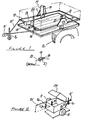
- Figures 1 and 2 shown in perspective and respectively, the basic framework and floor-dropping mechanism of the first embodiment, and the overall aspect of the first embodiment; whilst Figure 3 is a view corresponding to Figure 1 but referring to the second embodiment.
- a two-wheeled trailer rides on wheels referenced 11, 12 respectively.
- Each of these wheels is mounted via an INDESPENSION unit (INDESPENSION is a Trade Mark) to the framework 13 of the trailer body.
- the framework 13 is an essentially rectangular structure incorporating a towing frame extension 13' ending in a conventional towing hitch 15 and with a retractable nose wheel 16 mounted adjacent the hitch.
- the use of the INDESPENSION units instead of a common axle spanning the two wheels 11, 12, leave the underside of the trailer free for the trailer floor to be dropped and subsequently raised.
- the units are referenced 9, 10.
- the floor itself is based around an essentially rectangular framework 14 which is boarded or otherwise floored-in.
- the framework 14 fits closely within the framework 13 but is an easy non-sliding fit within that framework 13.
- the two frameworks are permanently linked to one another by respective double-acting hydraulic rams 17, 18 and by respective telescoping slide bars 19, 21.
- the cylinder of each ram 17, 18 is firmly fixed to a respective opposite longitudinal side member of the framework 13 to stand in a substantially vertical upright position when the trailer is in its normally intended attitude of use.
- the rod end of each ram is fixed to the corresponding side member of the framework 14; but it is pivotally fixed, not rigidly fixed.
- each telescoping slide bar unit 19, 21 are fixed respectively to side members of the frameworks 13 and 14; but, unlike the rams, each opposite end of the two parts of each slide bar unit is rigidly fixed to its associated frame member.
- a small hydraulic pump 22 is linked by fluid supply lines (conventionally ) to each of the rams 17, 18.
- the rams are double-acting rams, and the pump 22 may be a hand-bar- operated pump (the hand bar 23 is shown stowed on a clip 24 fixed to the trailer body).
- the trailer body has walls, and the back wall 25 hinges open and shut about one end-axis 26.
- a spring-loaded detent 27 engages under the trailer floor when the floor is fully raised and in use for transporting goods.
- a hand button 28 can be pulled out against the spring force to release the detent 27 and allow the trailer floor to be dropped.
- the pump 22 is operated, and exhausts fluid progressively from the rams 17, 18 to give a cushioned lowering movement to the floor.
- the floor reaches the ground on which the trailer stands, having maintained a substantially horizontal attitude throughout its dropping movement, goods can be moved off or loaded onto the floor once the tailgate 25 has been swung open.
- the pump 22 can be operated in the opposite sense to pressurise the rams 17, 18 and raise the floor until the two frameworks 13, 14 nest. As the floor comes fully home, the framework 14 automatically rides past the detent 27 and then the detent 27 similarly automatically locks into position beneath the framework 14.
- the pressurised rams 17, 18 constitute the main means holding the trailer floor in place during transport of goods.
- the spring loaded locking detent 27 is purely a safety catch in case the rams should fail.
- the rams 17, 18 are of course pressurised and de-pressurised simultaneously during use. The details of the hydraulic circuitry will be apparent without further inventive thought to the intended skilled addressee of this specification.
- a rigid preformed canopy 29 hinges about the top edge of the front wall of the trailer as illustrated in Figure 2.
- the whole body including the back wall could hinge as just described, so removing the back wall from the path of the on-loading or off-loading goods without the need to provide a hinge axis specific to the back wall.
- the floor of the trailer shown in Figure 3 is, like that of the Figures 1 and 2 embodiment, comprised of an essentially rectangular framework 29 which is boarded-in.
- the body of this second trailer again like that of the first trailer of Figures 1 and 2, has walls which rise from a framework 31 within which the frame 29 nests.
- the trailer body has only three walls (a front wall 32 and two opposed side walls 33, 34).
- the wall which, in use, forms the tailgate of this trailer (and which corresponds to the wall 25 of the first trailer) is hinged, not to the trailer body but to the back edge of the trailer floor framework 29.
- This tailgate 3 5 of the second trailer thus swings about a horizontal, not a vertical, axis when the trailer stands on level ground.
- chains 36 link the tailgate 35 to respective uprights 37, 38 rising from the floor framework 29 and limit the swinging-open movement of the tailgate to a position, illustrated in Figure 3, in which the tailgate 35 forms an extension of the floor of the trailer and is substantially horizontal when the floor is substantially horizontal.
- the tailgate 35 moves up and down with the trailer floor.
- the tailgate 35 can be swung up against the end faces of the side walls 33, 34. In that position, catches(7,8) secure the tailgate 35 to the trailer walls 33, 34.
- the catches which are of course readily releasable, can be selected from known alternatives.
- the uprights 37, 38 are rigid uprights and rise one from each of two adjacent corners of the trailer floor framework 29.
- Identical and further uprights 39, 41 rise from each of the two remaining corners of the rectangular peripheral floor framework 29.
- All four uprights are rigidly welded to the framework, and rigid struts 42, 43 run respectively between uprights 37, 39 and 38, 41 parallel.
- the struts 42, 43 are non-pivotally fixed at each of their opposite ends to their associated uprights. They run, as shown, parallel with the trailer side walls 33, 34.
- a third strut 44 is similarly inherently rigid and rigidly fixed to the uprights 39, 41 so as to span these two uprights.
- Rigid links 45, 46 are each pivoted at their respective lower ends to the trailer body side wall 33 and at their upper ends to a respective one of the uprights 37, 39.
- Corresponding and identical links are similarly pivoted to the other side wall 34 and to the remaining uprights 38, 41.
- Each pair of these links forms with its associated uprights and upright-spanning strut a parallellogram linkage.
- the two parallellogram linkages thereby defined suspend the floor and floor framework 29, and the tailgate 35, from the trailer body.
- a hand-operated cable winch 49 is mounted on a beam 51 which runs between the hitch-supporting framework 52 and the front wall 32 of the trailer.
- the winch cable pierces the front wall 32 via a slot 53 in that wall, and is fixed to the front edge of the trailer floor framework 29.
- a plunger 54 is spring-loaded to push the trailer floor framework 29 away from the trailer front wall 32. With the framework 29 nested within the trailer body, the front of the framework presses the plunger 54 against the spring-loading and into its housing (in frame 29). In this situation, the winch cable is taut; but it is the catches, holding the tailgate 35 against the walls 33, 34, which primarily hold the trailer floor in the body. Should the winch cable slacken, or break, these fastened catches will prevent the floor from dropping from the trailer.
- the winch 49 is unwound.
- the plunger 54 starts the floor and floor framework 29 moving, because in the nested position of the floor the links 45, 46, 47, 48 are all upright or slightly °over-centre°.
- the winch unwinds, the floor swings in an arc about the link side wall pivots, and eventually rests on the ground.
- the floor can then be winched up again into its nested position, the tailgate 35 swung up against the back edges of the side walls 33, 34, and the tailgate-retaining catches fastened against the side walls 33, 34.
- the second embodiment of Figure 3 is supported on pneumatically tyred wheels each attached to the trailer body by INDESPENSION units or their equivalent, 9, 10.
Landscapes
- Engineering & Computer Science (AREA)
- Transportation (AREA)
- Mechanical Engineering (AREA)
- Chemical & Material Sciences (AREA)
- Combustion & Propulsion (AREA)
- Body Structure For Vehicles (AREA)
- Handcart (AREA)
Applications Claiming Priority (2)
| Application Number | Priority Date | Filing Date | Title |
|---|---|---|---|
| GB868611257A GB8611257D0 (en) | 1986-05-08 | 1986-05-08 | Drop-floor trailer |
| GB8611257 | 1986-05-08 |
Publications (2)
| Publication Number | Publication Date |
|---|---|
| EP0245104A2 true EP0245104A2 (de) | 1987-11-11 |
| EP0245104A3 EP0245104A3 (de) | 1988-01-13 |
Family
ID=10597529
Family Applications (1)
| Application Number | Title | Priority Date | Filing Date |
|---|---|---|---|
| EP87304102A Withdrawn EP0245104A3 (de) | 1986-05-08 | 1987-05-08 | Anhänger mit absenkbarem Boden |
Country Status (4)
| Country | Link |
|---|---|
| EP (1) | EP0245104A3 (de) |
| AU (1) | AU7259087A (de) |
| GB (2) | GB8611257D0 (de) |
| ZA (1) | ZA873292B (de) |
Cited By (10)
| Publication number | Priority date | Publication date | Assignee | Title |
|---|---|---|---|---|
| DE3813495A1 (de) * | 1988-04-22 | 1989-11-02 | Hubert Willing | Anhaenger |
| WO1995026280A1 (en) | 1994-03-22 | 1995-10-05 | Tradesman Industries Inc | Vehicle with vertically adjustable loading bed |
| BE1008214A3 (nl) * | 1993-10-29 | 1996-02-13 | Geerinck Luc Casimir Denise | Aanhangwagen. |
| DE29621355U1 (de) * | 1996-12-10 | 1998-04-09 | Bremer, Dieter, 38315 Schladen | Fahrzeuganhänger |
| AU704241B2 (en) * | 1994-03-22 | 1999-04-15 | Workman Industries Pty Ltd | Vehicle with vertically adjustable loading bed |
| US6648578B1 (en) * | 2002-03-28 | 2003-11-18 | Richard W. Rouse | Trailer and lift assembly for same |
| US7976265B2 (en) | 2008-05-29 | 2011-07-12 | Merlin Badry | Ground level loading trailor |
| US8668426B1 (en) | 2013-02-08 | 2014-03-11 | Ben Baron | Drop-floor trailer |
| CN104176149A (zh) * | 2014-08-21 | 2014-12-03 | 刘东武 | 一种挖掘机运输拖行车 |
| FR3053308A1 (fr) * | 2016-07-04 | 2018-01-05 | Jacques Bianchetti | Remorque routiere a plateau pendulaire relevable |
Families Citing this family (6)
| Publication number | Priority date | Publication date | Assignee | Title |
|---|---|---|---|---|
| US5536131A (en) * | 1993-09-20 | 1996-07-16 | Behr; Albert | Utility trailer with level load support to and from the ground |
| GB2324278A (en) * | 1997-02-20 | 1998-10-21 | J & A Promotions Ltd | Vehicle with vertically movable deck |
| US5906470A (en) * | 1997-05-20 | 1999-05-25 | Desjardins; Lucien | Arch trailer for motorcycle transport and camping |
| US6123495A (en) * | 1998-06-16 | 2000-09-26 | Robertson Aviation L.L.C | Transport for moving and loading an auxiliary fuel tank |
| GB0221128D0 (en) * | 2002-09-12 | 2002-10-23 | Francis Robert | Trailers |
| US20050220591A1 (en) | 2004-04-05 | 2005-10-06 | Doskocil David L | Level lift trailer with detachable cargo bed |
Citations (3)
| Publication number | Priority date | Publication date | Assignee | Title |
|---|---|---|---|---|
| US3130980A (en) * | 1960-04-29 | 1964-04-28 | Magline Inc | Elevatable trailers |
| US3468440A (en) * | 1967-05-17 | 1969-09-23 | Harold George Poole | Vehicles |
| DE2804261A1 (de) * | 1977-02-04 | 1978-08-10 | Paul Geerinck | Kleiner anhaengewagen |
Family Cites Families (8)
| Publication number | Priority date | Publication date | Assignee | Title |
|---|---|---|---|---|
| GB1107763A (en) * | 1963-10-16 | 1968-03-27 | Poole Harold George | Improvements in or relating to vehicles |
| US3520429A (en) * | 1967-06-28 | 1970-07-14 | Haegglund & Soener Ab | Transport vehicle for heavy loads |
| GB1234630A (de) * | 1968-10-08 | 1971-06-09 | ||
| DE2754009A1 (de) * | 1976-12-07 | 1978-06-08 | Donald Workum | Fahrzeug zum transportieren von lasten |
| IE50752B1 (en) * | 1980-05-21 | 1986-07-09 | Inst For Ind Res & Standards | A construction of trailer |
| GB2104487A (en) * | 1981-08-18 | 1983-03-09 | Timothy Raymond Warner | Materials handling system and apparatus |
| IL66627A (en) * | 1982-08-23 | 1985-02-28 | Hechtometal Handassa Technith | Means for loading fowl into a transporting vehicle |
| GB2139179A (en) * | 1983-04-20 | 1984-11-07 | Michael Ernest Smethurst | Improvements in trailers |
-
1986
- 1986-05-08 GB GB868611257A patent/GB8611257D0/en active Pending
-
1987
- 1987-05-07 AU AU72590/87A patent/AU7259087A/en not_active Abandoned
- 1987-05-08 EP EP87304102A patent/EP0245104A3/de not_active Withdrawn
- 1987-05-08 ZA ZA873292A patent/ZA873292B/xx unknown
- 1987-05-08 GB GB08710937A patent/GB2190349A/en not_active Withdrawn
Patent Citations (3)
| Publication number | Priority date | Publication date | Assignee | Title |
|---|---|---|---|---|
| US3130980A (en) * | 1960-04-29 | 1964-04-28 | Magline Inc | Elevatable trailers |
| US3468440A (en) * | 1967-05-17 | 1969-09-23 | Harold George Poole | Vehicles |
| DE2804261A1 (de) * | 1977-02-04 | 1978-08-10 | Paul Geerinck | Kleiner anhaengewagen |
Cited By (12)
| Publication number | Priority date | Publication date | Assignee | Title |
|---|---|---|---|---|
| DE3813495A1 (de) * | 1988-04-22 | 1989-11-02 | Hubert Willing | Anhaenger |
| BE1008214A3 (nl) * | 1993-10-29 | 1996-02-13 | Geerinck Luc Casimir Denise | Aanhangwagen. |
| WO1995026280A1 (en) | 1994-03-22 | 1995-10-05 | Tradesman Industries Inc | Vehicle with vertically adjustable loading bed |
| US5630693A (en) * | 1994-03-22 | 1997-05-20 | Workman Industries Pty Limited | Vehicle |
| US5820149A (en) * | 1994-03-22 | 1998-10-13 | Workman Industries Pty Limited | Wheel suspension assembly |
| AU704241B2 (en) * | 1994-03-22 | 1999-04-15 | Workman Industries Pty Ltd | Vehicle with vertically adjustable loading bed |
| DE29621355U1 (de) * | 1996-12-10 | 1998-04-09 | Bremer, Dieter, 38315 Schladen | Fahrzeuganhänger |
| US6648578B1 (en) * | 2002-03-28 | 2003-11-18 | Richard W. Rouse | Trailer and lift assembly for same |
| US7976265B2 (en) | 2008-05-29 | 2011-07-12 | Merlin Badry | Ground level loading trailor |
| US8668426B1 (en) | 2013-02-08 | 2014-03-11 | Ben Baron | Drop-floor trailer |
| CN104176149A (zh) * | 2014-08-21 | 2014-12-03 | 刘东武 | 一种挖掘机运输拖行车 |
| FR3053308A1 (fr) * | 2016-07-04 | 2018-01-05 | Jacques Bianchetti | Remorque routiere a plateau pendulaire relevable |
Also Published As
| Publication number | Publication date |
|---|---|
| ZA873292B (en) | 1988-01-27 |
| GB8710937D0 (en) | 1987-06-10 |
| GB8611257D0 (en) | 1986-06-18 |
| AU7259087A (en) | 1987-11-12 |
| GB2190349A (en) | 1987-11-18 |
| EP0245104A3 (de) | 1988-01-13 |
Similar Documents
| Publication | Publication Date | Title |
|---|---|---|
| EP0245104A2 (de) | Anhänger mit absenkbarem Boden | |
| US5403024A (en) | Foldable lightweight pallet carrier | |
| US6821075B2 (en) | Hoist with trailer hitch attachment | |
| US4155471A (en) | Trailer/container unit | |
| US4372727A (en) | Trailer including a multiple fold powered ramp tail | |
| US5443350A (en) | Goods vehicle or a trailer for a goods vehicle | |
| US4571139A (en) | Self-propelled freight handling truck | |
| RU2461486C2 (ru) | Складной прицеп | |
| US4647270A (en) | Transporting unit for trucks and the like | |
| US9656587B2 (en) | Tiltloader for transferring cargo | |
| US20040156703A1 (en) | Hoist for loading and unloading objects on a truck bed | |
| US2792079A (en) | Material handling apparatus | |
| US4126357A (en) | Demountable tilting container assemblies for light vans and trucks | |
| US4087007A (en) | Cargo platform system | |
| US4740132A (en) | Device for handling containers | |
| US6799935B1 (en) | Lifting apparatus for user in the bed of a pickup truck | |
| US5562391A (en) | Modular unit loading and unloading apparatus | |
| US20090202328A1 (en) | Low profile hook hoist | |
| US4509894A (en) | Loading and unloading apparatus for a vehicle | |
| US20050254925A1 (en) | Lift apparatus for an all-terrain vehicle | |
| US5028198A (en) | Collapsible full reach truck bed hoist | |
| US6830422B2 (en) | Container transport apparatus | |
| US5184872A (en) | Dumping semi-trailer | |
| EP0171396B1 (de) | Selbstladesystem | |
| US5494309A (en) | Self-loading piggyback-type trailer unit |
Legal Events
| Date | Code | Title | Description |
|---|---|---|---|
| PUAI | Public reference made under article 153(3) epc to a published international application that has entered the european phase |
Free format text: ORIGINAL CODE: 0009012 |
|
| AK | Designated contracting states |
Kind code of ref document: A2 Designated state(s): AT BE CH DE ES FR GB GR IT LI LU NL SE |
|
| PUAL | Search report despatched |
Free format text: ORIGINAL CODE: 0009013 |
|
| AK | Designated contracting states |
Kind code of ref document: A3 Designated state(s): AT BE CH DE ES FR GB GR IT LI LU NL SE |
|
| STAA | Information on the status of an ep patent application or granted ep patent |
Free format text: STATUS: THE APPLICATION IS DEEMED TO BE WITHDRAWN |
|
| 18D | Application deemed to be withdrawn |
Effective date: 19880114 |
|
| RIN1 | Information on inventor provided before grant (corrected) |
Inventor name: CHOWN, PETER ARTHUR CHARLES |