EP0245050A2 - Maschine und Verfahren zum geregelten Fliessdrücken von Dosen - Google Patents
Maschine und Verfahren zum geregelten Fliessdrücken von Dosen Download PDFInfo
- Publication number
- EP0245050A2 EP0245050A2 EP87303940A EP87303940A EP0245050A2 EP 0245050 A2 EP0245050 A2 EP 0245050A2 EP 87303940 A EP87303940 A EP 87303940A EP 87303940 A EP87303940 A EP 87303940A EP 0245050 A2 EP0245050 A2 EP 0245050A2
- Authority
- EP
- European Patent Office
- Prior art keywords
- container
- roller
- holder
- open end
- sleeve
- Prior art date
- Legal status (The legal status is an assumption and is not a legal conclusion. Google has not performed a legal analysis and makes no representation as to the accuracy of the status listed.)
- Granted
Links
- 238000000034 method Methods 0.000 title claims abstract description 25
- 229910052751 metal Inorganic materials 0.000 claims description 24
- 239000002184 metal Substances 0.000 claims description 24
- 230000006835 compression Effects 0.000 claims description 12
- 238000007906 compression Methods 0.000 claims description 12
- 230000007704 transition Effects 0.000 claims description 12
- 230000002093 peripheral effect Effects 0.000 claims description 11
- 238000009987 spinning Methods 0.000 claims description 11
- 235000013361 beverage Nutrition 0.000 claims description 4
- 238000005096 rolling process Methods 0.000 claims description 4
- 238000006073 displacement reaction Methods 0.000 claims 2
- 239000012530 fluid Substances 0.000 claims 2
- 230000008569 process Effects 0.000 abstract description 5
- 210000003739 neck Anatomy 0.000 abstract 4
- 230000013011 mating Effects 0.000 abstract 1
- 238000010409 ironing Methods 0.000 description 12
- 229910052782 aluminium Inorganic materials 0.000 description 8
- XAGFODPZIPBFFR-UHFFFAOYSA-N aluminium Chemical compound [Al] XAGFODPZIPBFFR-UHFFFAOYSA-N 0.000 description 8
- 229910000831 Steel Inorganic materials 0.000 description 5
- 239000010959 steel Substances 0.000 description 5
- 238000005336 cracking Methods 0.000 description 4
- 239000000314 lubricant Substances 0.000 description 4
- 230000004323 axial length Effects 0.000 description 3
- 238000005452 bending Methods 0.000 description 3
- 238000000576 coating method Methods 0.000 description 3
- 239000000463 material Substances 0.000 description 3
- 230000004044 response Effects 0.000 description 3
- 239000005028 tinplate Substances 0.000 description 3
- 239000004809 Teflon Substances 0.000 description 2
- 229920006362 Teflon® Polymers 0.000 description 2
- 230000009471 action Effects 0.000 description 2
- 239000002826 coolant Substances 0.000 description 2
- 239000004033 plastic Substances 0.000 description 2
- 229920003023 plastic Polymers 0.000 description 2
- 230000000750 progressive effect Effects 0.000 description 2
- 238000007789 sealing Methods 0.000 description 2
- 229910001209 Low-carbon steel Inorganic materials 0.000 description 1
- WYTGDNHDOZPMIW-RCBQFDQVSA-N alstonine Natural products C1=CC2=C3C=CC=CC3=NC2=C2N1C[C@H]1[C@H](C)OC=C(C(=O)OC)[C@H]1C2 WYTGDNHDOZPMIW-RCBQFDQVSA-N 0.000 description 1
- 230000015572 biosynthetic process Effects 0.000 description 1
- 239000000969 carrier Substances 0.000 description 1
- 230000008859 change Effects 0.000 description 1
- 239000011248 coating agent Substances 0.000 description 1
- 230000007797 corrosion Effects 0.000 description 1
- 238000005260 corrosion Methods 0.000 description 1
- 238000005034 decoration Methods 0.000 description 1
- 229920002457 flexible plastic Polymers 0.000 description 1
- 230000007246 mechanism Effects 0.000 description 1
- 239000007769 metal material Substances 0.000 description 1
- 150000002739 metals Chemical class 0.000 description 1
- 238000000465 moulding Methods 0.000 description 1
- 239000011087 paperboard Substances 0.000 description 1
- 238000003908 quality control method Methods 0.000 description 1
- 230000009467 reduction Effects 0.000 description 1
- 238000004826 seaming Methods 0.000 description 1
- 238000007493 shaping process Methods 0.000 description 1
- 230000037303 wrinkles Effects 0.000 description 1
Images
Classifications
-
- B—PERFORMING OPERATIONS; TRANSPORTING
- B21—MECHANICAL METAL-WORKING WITHOUT ESSENTIALLY REMOVING MATERIAL; PUNCHING METAL
- B21D—WORKING OR PROCESSING OF SHEET METAL OR METAL TUBES, RODS OR PROFILES WITHOUT ESSENTIALLY REMOVING MATERIAL; PUNCHING METAL
- B21D17/00—Forming single grooves in sheet metal or tubular or hollow articles
- B21D17/04—Forming single grooves in sheet metal or tubular or hollow articles by rolling
-
- B—PERFORMING OPERATIONS; TRANSPORTING
- B21—MECHANICAL METAL-WORKING WITHOUT ESSENTIALLY REMOVING MATERIAL; PUNCHING METAL
- B21D—WORKING OR PROCESSING OF SHEET METAL OR METAL TUBES, RODS OR PROFILES WITHOUT ESSENTIALLY REMOVING MATERIAL; PUNCHING METAL
- B21D22/00—Shaping without cutting, by stamping, spinning, or deep-drawing
- B21D22/14—Spinning
-
- B—PERFORMING OPERATIONS; TRANSPORTING
- B21—MECHANICAL METAL-WORKING WITHOUT ESSENTIALLY REMOVING MATERIAL; PUNCHING METAL
- B21D—WORKING OR PROCESSING OF SHEET METAL OR METAL TUBES, RODS OR PROFILES WITHOUT ESSENTIALLY REMOVING MATERIAL; PUNCHING METAL
- B21D51/00—Making hollow objects
- B21D51/16—Making hollow objects characterised by the use of the objects
- B21D51/26—Making hollow objects characterised by the use of the objects cans or tins; Closing same in a permanent manner
- B21D51/2615—Edge treatment of cans or tins
- B21D51/2638—Necking
-
- B—PERFORMING OPERATIONS; TRANSPORTING
- B65—CONVEYING; PACKING; STORING; HANDLING THIN OR FILAMENTARY MATERIAL
- B65D—CONTAINERS FOR STORAGE OR TRANSPORT OF ARTICLES OR MATERIALS, e.g. BAGS, BARRELS, BOTTLES, BOXES, CANS, CARTONS, CRATES, DRUMS, JARS, TANKS, HOPPERS, FORWARDING CONTAINERS; ACCESSORIES, CLOSURES, OR FITTINGS THEREFOR; PACKAGING ELEMENTS; PACKAGES
- B65D1/00—Rigid or semi-rigid containers having bodies formed in one piece, e.g. by casting metallic material, by moulding plastics, by blowing vitreous material, by throwing ceramic material, by moulding pulped fibrous material or by deep-drawing operations performed on sheet material
- B65D1/12—Cans, casks, barrels, or drums
- B65D1/14—Cans, casks, barrels, or drums characterised by shape
- B65D1/16—Cans, casks, barrels, or drums characterised by shape of curved cross-section, e.g. cylindrical
- B65D1/165—Cylindrical cans
Definitions
- This invention relates to containers; the body for such containers being in the form of cylindrical one-piece metal can having an open end terminating in an outwardly directed peripheral flange merging with a circumferentially-extending neck portion (the can body being hereinafter referred to as a D&I can).
- a D&I can a circumferentially-extending neck portion
- Methods of forming said neck and flange in a D&I can body and to apparatus for forming the said peripheral flange and neck portion are also the subject of this invention.
- the background for this disclosure relates to the way in which D&I can bodies are manufactured in drawing and then multiple ironing operations.
- beverage containers have been made by a drawing and then multiple ironing processes in which the metal material is first drawn into a cup to establish the shape and a basic inside diameter and the cup is then pushed through a series of ironing rings which merely thin the side wall and do not appreciably affect the diameter.
- the cross-sectional configuration of the ironing ring includes a chamfer, a land and finally a relief angle.
- the ironing process begins on the chamfer and is completed by the land during which time no drawing takes place. The process is done at high speed under a coolant/lubricant flood in order to accommodate the severity of the operation especially the heat.
- These containers have to be washed and in some cases chemically treated to remove residual lubricant and improve corrosion performance of organic coatings and decoration subsequently applied to the container. Coatings are normally applied after the shell has been trimmed and washed free of lubricants and metal fines.
- the ironing steps result from the difference between the clearance between a punch and ironing ring land and the thickness of the metal sidewall. That clearance represents the amount to which the side wall of the container will be thinned.
- metal with no organic coating passes through three different ironing rings in a D&I operation during which ETP electrolytic of T-1 to T-5 temper tinplate or H19 aluminum container sidewall is reduced about 25% in the first pass, about 25% of its new thickness in the second pass, and about 40% of its new thickness in the last pass, while the metal and tooling are flooded with lubricant coolant.
- This operation increases the side wall length to several times that of the cup which was formed in an ordinary and separate one or two-draw operation.
- the cleaned and trimmed D&I can may then be necked and flanged in a separate apparatus and an independent operation.
- the grain orientation of the ironed sidewall is highly directional and the D&I can is subject to longitudinal cracking particularly at the radially extending flange.
- the purpose of the peripheral flange is usually to provide an element to which a can end is secured after the can has been filled, this securing being done by deforming the end flange of the can body together with a peripheral cover hook of the can end so as to form a double seam. Consequently, flange cracks are a problem to achieving a hermetic double seam.
- the neck enables the flange, and therefore the can end, to be of smaller diameter than if there were no neck; usually the radial depth of the neck is such that the double seam has an external diameter less than that of the cylindrical side wall. Necking also minimizes the radial extent of the flange thus helping to resist flange cracking.
- the end to be seamed on to the flange of the can body is preformed with the scored opening feature.
- These opening features often determine the diameter of the end and only recently has the tab-type been reduced in size to permit ends as small as 202 bei e double seam (can makers conventional terminology).
- the end neck may serve another purpose, which is to provide a convenient means whereby a carrier can engage the container; such carriers are designed to hold a plurality of containers and may be of, for example, paperboard or a flexible plastic material.
- the type of carrier which engages the neck of a container of the kind with which this disclosure is concerned may include a horizontal web in which there are a plurality of holes, the periphery of each hole engaging below the above-mentioned container double end seam so as to support the container wholly or partly thereby.
- the neck can be so shaped as to provide some measure of support and/or restraint for the carrier web around the hole in the latter, and to assist in locking the container to the web until the user wishes to pull it away from the carrier.
- a reduced neck allows the cans to be held in close parallel relation thus, minimizing the total space needed to hold the containers.
- the necked end can be designed to stack against the bottom of a similar container for ease of shipping.
- Some methods involve molding the neck and/or the flange by means of circumferentially extending molds. Die necking has also been used to longitudinally move a die against the end of a supported D&I can to force same to a smaller diameter by means of the application of the die.
- Other methods involve rolling or spinning the neck and/or flange, using an external spinning roll of a given shape co-operating with an internal member of a companion shape within the can body. In these latter methods, the can body is supported rigidly by an internal mandrel or the like; the internal member may be a spinning roll, pilot or it may be the mandrel which supports the can body.
- the neck and flange are formed simultaneously in a can body supported internally and rigidly by a mandrel or chuck of an expanding/collapsing type, the neck and flange profile being formed by external spinning rolls co-operating with this mandrel.
- the can body is supported internally by an anvil and endwise by a spinning pilot, the neck and flange being formed by a profiled, external spinning roll which deforms the can body into a groove formed on the pilot and anvil, the roll being moved axially of the can body.
- the final profile of the neck and flange is determined by the set profiles of the tool elements used for forming them, in that the tool elements (i.e., spinning rolls, mandrels, anvil etc. are provided rigidly with fix working surfaces shaped to conform with the ultimate shape of the neck and/or the flange, and the metal of the can body is deformed into conformity with these profiles. It is thus necessary, if a different shape is requred to change the tools so as to provide differently profiled tool elements.
- the tool elements i.e., spinning rolls, mandrels, anvil etc.
- a method such as that mentioned above, in which an expanding mandrel is used enables end flanges and neck portions to be produced reliably and economically even on can bodies made in the thinner and harder metals currently in favor, in particular double-reduced plate which is usually tinplate, but which may, for example, be aluminum, mild steel or blackplate suitably treated but not necessarily plated with another metal.
- the present invention is also especially suitable for use with these thinner and harder double reduced or work hardened materials.
- Disclosed hereinafter is a unique tool for flow sin forming the opened end of thin wall D&I cans, a method for using that tool and a unique container configuration easily obtainable at commercial speeds by application of that tool with that method.
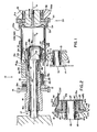
- An apparatus 10 including a externally positioned roller 11 mounted on a mandrel 12, supported for full rotation by bearing 13 captured between the roller 11 and mandrel 12 to allow roller 11 to freely rotate with respect to its mounting yoke 14.
- the contour of the nose of periphery of roller 11, as shown in Figure 1 includes flat 11a, a leading portion 11b and a trailing port 11c.
- the mandrel 12 has a greater axial length than the mounting hub 11d for the peripheral roller 11 whereby the roller 11 is free to slide, along the mandrel 12 against the urgings of a coil compression spring 12a which sets about mandrel 12 in reaction to axial thrust applied to the roller 11 during spin flow forming.
- the yoke 14 is mounted for controlled movement toward and away from the axis A of the apparatus 10 such as, for example, by a timed cam means.
- the spinning device to drive the D&I can to be necked and flanged by spin flow forming is composed of a can support 15 which includes a gear drive 16 and its extended hub 16a, mounting bearings 17 within the extended ends of the hub 16a, which ride upon a fixed support shaft 18 and a D&I can end holder 19.
- the bearings 17 are disposed between shaft 18 and the hub 16a of gear 16.
- Shaft 18 is merely a fixed support and as such is not drivingly rotatable along its axis A.
- Holder 19 is shaped with a chamfered leading edge portion 19a designed to first engage the open end of a trimmed D&I can and then to support same for rotation about axis A in connection with the drive of gear 16 through the hub 16a therefore.
- Holder 19 is also free to slide axially relative to fixed liently biased into the open D&I can end by springs 20 (only one of which is shown in Figure 1).
- the springs 20 are of the compression coil type and are captured in counter bored holes for controlled alignment and positioning.
- a driving collar 21 is mounted on hub 16a and arranged to rotate about shaft 18 in accordance with the drive from gear 16. More particularly, collar 21 has a set screw 21a to attach collar 21 to hub 16a and hold same adjacent gear 16 so that collar 21 is disposed with its counter bored holes 21b set to receive the springs 20 and locate same as to extend to holder 19.
- Shaft 18 also carries a fixed inner roller assembly 22 which is mounted on an enlarged diameter (relative to the diameter of shaft 18) eccentrically disposed end 18a of shaft 18. More particularly, end 18a is cylindrical and offset to one side of the axis A such that it has a center line B. The offset is such that it is positioned at the center of the larger diameter of end 18a 8 whereby the end 18a has one side which is in line with the side of shaft 18 and the other side which is offset relative thereto. Between the sides of end 18a and the roller assembly 22 there are bearings 23 which are a part of roller assembly 22 and support same for free rotation about axis B.
- the roller assembly 22 also includes a roller sleeve 24 having an inner diametrical surface 24a supported on bearings 23, an outer contoured surface 24b which is adapted to engage a part of the inside wall of the D&I can, a front face 24c and a rear face 24d.
- the latter is adapted to abut the portion 19a and more specifically, the face thereof when same is urged outwardly of collar 21.
- Roller assembly 22 is restrained from axial movement relative to shaft end 18a by an inner axial bearing 25 disposed between the roller sleeve 24, rear face 24d and the holder 19.
- holder 19 includes a recessed inner bore 19c which provides space for receiving the axial thrust bearing 25 and thereby limits the motion of holder 19 axially outwardly in response to the urgings of springs 20 whereby in its outwardmost position (holder 19 to the right in Figure 1) abuts at 19a near face 24d of the sleeve but really against thrust bearing 25..
- sleeve 24 The outer end of sleeve 24 is maintained by means of a thrust bushing 26 in a form of a washer which during assembly is slid over end 18a and is held axially thereon by a retaining ring 27 disposed within a groove 18b circumscribed about the distal periphery of end 18a. Consequently, sleeve 24 is held in position between the bushing 26 and the bearing 25 so its axial location, relative to end 18a is fixed.
- Bearing 25 acts as a stop for the outward axial motion of holder 19 but the location of bearing 25 is defined by the hub 16a upon which gear 16 is carried.
- the hub has bearings 17, as already mentioned, which ride on fixed shaft 18 and hub 16a extends to the right through attached collar 21 to its end 16b which abuts bearing 25 and carries bearing 17 inside that end.
- hub 16a is free to rotate relative to shaft 18 but because of a keyed relationship between hub 16a and in particular a keyway 16c on hub 16a and 19d on holder 19 axial movement between holder 19 and hub 16a is permitted even though holder 19 rotates with hub 16a.
- a key 28 which acts like a spline to permit the axial motion of the holder 19 outwardly in response to the urgings of springs 20.
- the D&I can is supported by its bottom which includes vacuum.
- Figure 1 illustrates a convenient means by which the bottom of a container may be supported along a s as it is rotated.
- a chuck assembly 29 which includes a gear 30 driven at the same speed and in a manner similar to that used to drive gear 16.
- Gear 30 has a center hub 31 which is provided with an axially positioned vacuum passage to permit vacuum to pass therethrough for purposes of holding the bottom of the D&I can.
- Hub 31 is supported cantilever on a bearing 32 whereby gear 30 can rotate when driven about axis A.
- a cup 33 is mounted to the face 30A of gear 30 and extends outwardly therefrom along axis A toward the bottom of the D&I can.
- Cup 33 is designed to carry an O-ring 34 within the inwardly (radial) rolled end thereof 33a in order to define a place against which the D&I can bottom can be sealed in order to maintain the vacuum established through the hub 31.
- hub 31 has an extending flange 31a against which the bottom of the D&I can rests whereby the lower side wall is sealingly engaged with the O-ring 34.
- the yoke 14 first carries peripheral roller 11 laterally towards axis A to initially engage the side wall of the open trimmed end of the D&I can.
- the roller 11 is positioned relative to the sleeve 24 so that, upon such initial engagement with the D&I can, a portion of the outer edge of the trailing portion 11c of roller 11 and a portion of the outer edge of the chamfer portion 24e of sleeve 24 are disposed substantially edge-to-edge with the D&I can in contact with each therebetween to define an initial nip on the D&I can.
- the chamfer portion 24e of the sleeve 24 cooperates with the trailing portion 11c to define the angle of the conical neck for the D&I can. Any reasonable obtuse (with respect to the inside wall) angle is obtainable.
- the holder 19 is spring loaded axially outward (to the right) to engage the radially inwardly moving roller 11. More specifically, the lead portion 11b of roller 11 interfaces through the D&I can with the chamfer portion 19cf of holder 19 so that the roller 11 will be urged under the spring force of coil springs 20 towards chamfer portion 24e of sleeve 24.
- the offset between axis A and axis B is provided in order to permit removal of the necked container notwithstanding the larger diameter of assembly 22. More particularly, the diameter to which the container is necked is still greater than the diameter of the assembly 22 whereby release of the conically necked D&I can from the chunk assembly 29 permits the container to tip relative to its axis A and slide over the outset of eccentric assembly 22.
- roller 11 is a unitary or one-piece roller, applicable primarily for the deformation of steel containers or shells.
- Fig. 2 shows a modified version, a roller assembly 40, including a peripheral (split) nose portion 41 with a peripheral flat 41a intended to be opposed to aluminum container bodies for reasons to be explained.
- roller assembly 40 comprises two complemental roller sections 40a and 40b.
- roller section 40a includes a shank or sleeve 42 mounted for free rotation concentrically about the supporting mandrel 12 (described above), an antifriction bushing 44 of Teflon plastic or the like being interposed between the two.
- Roller section 40a also includes a radial flange 45 having a leading portion 45b, the outer periphery of which presents a portion of the flat 41a as will be evident in Fig. 2.
- roller section 40a The back of the flange 45 of roller section 40a is flat. Opposed thereto is the radial face of roller section 40b, undercut or recessed in part to receive an antifriction washer 47 such as Teflon plastic or the like.
- roller section 40b is flush with the outer periphery of roller 40a to complete the flat 41a.
- the roller section 40b is tapered or sloped radially inwardly to define a trailing portion 40c, as in the instance of the unitary roller 11 of Fig. 1.
- An antifriction bushing 50 is interposed between the outer diameter of the sleeve 42 and the inner diameter of roller section 40b so that the two roller sections may freely rotate relative to one another at different speeds.
- the roller assembly is completed by disc 51 fitting flush against the radially aligned rear faces of the two roller sections.
- Disc 51 is bolted (at the dashed lines 51a, Fig. 2) to the sleeve portion of roller section 40a.
- the leading portion 45b of roller section 40a performs the same function as the leading portion 11b of roller 11 described above.
- Trailing portion 40c of roller section 40b performs the same function as trailing portion 11c of roller 11 described above.
- the roller assembly 40 is split compared to roller 11 and because of this the two roller sections can rotate independently at different speeds as an incident to engagement with the container being spun. This independent action of the two roller sections precludes wrinkles from occurring in the necked-in conical surface being formed at the open end of the container.
- the wider roller section 40b compared to roller section 40a, will rotate at a faster speed because its trailing portion 40c is being driven by the greater can diameter at the open end of the can clamped between the taper 40c of roller section 40b and the opposed surface 24e of axially fixed sleeve 24 inside the can, while at the same time the nose portion of roller section 40a which helps to form the nose or flat 41a is engaging a smaller diameter of the can being spun as shown in Fig. 2.
- anti-friction means may be substituted, and different support means as well.
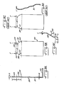
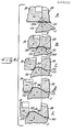
- the material of which these one-piece container bodies are made is quite thin as the result of drawing (lengthening the initial thick walled cup-shaped blank) and repeatedly ironing (progressively thinning and lengthening) the drawn body 100, Fig. 3B.
- the final wall thickness "m" along the major portion of the longitudinal axis (side wall section 101, Fig. 3A) may be 0.003+ inches in the case of steel and 0.004+ inches in the case of aluminum, for example.
- the bottom wall 102 is not ironed.
- the open end or rim portion 103 at "p" has a greater wall thickness, say 0.006+ inches in the case of steel and 0.007+ inches in the case of aluminum. This is due to the ironing process because the excess metal from ironing the side wall accumulates at and thickens the rim portion.
- the flange for receiving the closure lid is formed from the rim thickness "o" which is typically 3/8 to 1 ⁇ 2 inch in axial length as shown in Fig. 3A. Structuring the flange will be described in more detail below.
- transition zone 104 Between the rim and the thinner side wall, there is usually a transition zone 104, Fig. 3A, of variable, tapered thickness "n", thinnest where it meets the side wall diameter and thickest where it meets the rim portion diameter. Typically this transition zone has a length of 7/16 to 1 ⁇ 2 inch, Fig. 3A.
- the diameter of the open end may be considerably reduced thereby saving on the amount of metal for the lid, and there are other attendant advantages as noted above.
- Fig. 3D reduction in diameter at the neck is done by a multiple number of dies employed to reduce the diameter in stages, each producing an arcuate bend and imparting a sinusoidal shape.
- an effort is afterwards made to straighten these bends but the result is imperfect due to spring-back. Indeed, some concavity results and it is not possible to straighten the first bend B1 adjacent the side wall which is critical.
- Fig. 4 shows on an enlarged scale progressive formation of the container at its open end in accordance with the present invention. It is to be understood the container body presenting side wall 101 is spinning, along with sleeve 24 and holder 19, Fig. 4.
- the side wall of the spinning container body is a straight cylindrical section of generally uniform diameter and thickness, as already noted, extending from the closed bottom wall 102 to a diameter termed herein the transition diameter 105 which is designated in Fig. 4B.
- a truncated cone commences to be formed with the transition zone diameter 105 constituting the base of the cone. That is, the base of the container cone and the transition diameter 105 are coincident as is evident in Figs. 3A and 3B.
- the side wall 108 of the cone increases in length to the left of the initial nip (as does the "height" of the cone) as the external die roller chamfer (e.g. the truncated cone chamfer 11c, Fig. 1) continues to squeeze or press the container metal along the complemental slope or truncated cone 24e of sleeve 24.
- the cones as 11c and 24e in the geometric sense are similar and regular so that the truncated cone, which becomes the necked-in portion of the container body, is generated as a true or regular cone 110, Fig. 3B, with an included angle 112 between the base 105 of the cone and the cone side wall 108.
- the included angle preferably shall not be greater than 60°-62°.
- the cone continues to be generated as the external roller (11,45) advances radially inwardly (holder 19 continues to retract axially) until a reduced diameter 115 is achieved, Fig. 3B, constituting the throat diameter D of the container; diameter 115 is also the diameter of the top of the truncated cone. It is here that the throat of the container commences to be formed as will soon be described.
- the rim portion 103 of the container body, Fig. 4B conforms to the lead chamfer of the roller (e.g. 11b) and is retracted along the complemental chamfer 19cf at the end of holder 19, Fig. 4D, eventually becoming an outwardly bent flange 123 of the container as shown in Fig. 3B.
- the container is formed with a short throat 124.
- the throat 124 is a straight or regular cylinder of uniform diameter D, extending from the throat diameter 5 to the short or inside diameter of the flange 123.
- the side wall of the throat 124 is straight, formed by the flat rim 11a of the external (die) roller as 11. (It makes no difference whether roller 11 is being used or roller 40, Fig. 2).
- the throat may have an axial length of about 3/6 inch corresponding to the rim or "flat" (11a, 41a) of the external forming roller.
- This flat rim on the roller has small radii at its edges to avoid scratches and sharp bends in the container body. It can be seen in Fig. 4 that the throat 124 is formed concurrently with the cone, while the flange 123 is the last to be formed.
- 3C is a weak curved spring, easily flexed and crumpled by an axial load F. It will be readily recognized the same weak features are present when the geometry shown in Fig. 3D is employed, although to a lesser extent when there is an attempt to smooth out the bends shown in Fig. 3D.
- the included angle 112 of 60°-62° is critical in several respects. These containers are to be filled with beverages, involving a valved filling nozzle assembly pressed downward against the open end of the container. A container with crush strength up to 300 pounds of axial loading therefore becomes important in this regard, and it is also important from the standpoint of subsequent handling and stacking. Coupled to this is the need to achieve maximum filling capaci ty and enough room at the throat section for the roller (not shown) which curls or wraps the edge of the lid (not shown) around the perimeter of the flange 123 when the top is hermetrically sealed. During sealing, the can is under compression along its longitudinal axis so that crush strength is again important.
- An included angle 112 of 60°-62° translates an axial load on the container into an appreciable compression load component on the cone side wall designated F T in Fig. 3E which in turn has a component F B tending to buckle the container side wall 101 inward and the magnitude of F B depends on angle 112 by sine-consine values.
- F T in Fig. 3E which in turn has a component F B tending to buckle the container side wall 101 inward and the magnitude of F B depends on angle 112 by sine-consine values.
Landscapes
- Engineering & Computer Science (AREA)
- Mechanical Engineering (AREA)
- Ceramic Engineering (AREA)
- Shaping Metal By Deep-Drawing, Or The Like (AREA)
- Press Drives And Press Lines (AREA)
- Pens And Brushes (AREA)
- Containers Having Bodies Formed In One Piece (AREA)
Priority Applications (1)
| Application Number | Priority Date | Filing Date | Title |
|---|---|---|---|
| AT87303940T ATE84455T1 (de) | 1986-05-02 | 1987-05-01 | Maschine und verfahren zum geregelten fliessdruecken von dosen. |
Applications Claiming Priority (2)
| Application Number | Priority Date | Filing Date | Title |
|---|---|---|---|
| US858774 | 1986-05-02 | ||
| US06/858,774 US4781047A (en) | 1983-10-14 | 1986-05-02 | Controlled spin flow forming |
Publications (3)
| Publication Number | Publication Date |
|---|---|
| EP0245050A2 true EP0245050A2 (de) | 1987-11-11 |
| EP0245050A3 EP0245050A3 (en) | 1988-03-30 |
| EP0245050B1 EP0245050B1 (de) | 1993-01-13 |
Family
ID=25329141
Family Applications (1)
| Application Number | Title | Priority Date | Filing Date |
|---|---|---|---|
| EP87303940A Expired - Lifetime EP0245050B1 (de) | 1986-05-02 | 1987-05-01 | Maschine und Verfahren zum geregelten Fliessdrücken von Dosen |
Country Status (7)
| Country | Link |
|---|---|
| US (1) | US4781047A (de) |
| EP (1) | EP0245050B1 (de) |
| JP (1) | JPS63115623A (de) |
| AT (1) | ATE84455T1 (de) |
| AU (1) | AU6297886A (de) |
| DE (1) | DE3783509T2 (de) |
| GR (1) | GR3007501T3 (de) |
Cited By (3)
| Publication number | Priority date | Publication date | Assignee | Title |
|---|---|---|---|---|
| WO1997049509A1 (en) * | 1996-06-21 | 1997-12-31 | Carnaudmetalbox Plc | Can shaping |
| EP2791032A4 (de) * | 2012-11-05 | 2016-07-20 | Ball Corp | Konturierter hals für einen getränkebehälter |
| USD870567S1 (en) | 2012-08-29 | 2019-12-24 | Ball Corporation | Contoured neck for a beverage container |
Families Citing this family (51)
| Publication number | Priority date | Publication date | Assignee | Title |
|---|---|---|---|---|
| US4927043A (en) * | 1987-11-13 | 1990-05-22 | Ihly Industries, Inc. | Necked-down can having a false seam and an apparatus to form same |
| US4870847A (en) * | 1988-05-20 | 1989-10-03 | Ihly Industries, Inc. | Method and apparatus for forming outwardly projecting beads on cylindrical objects |
| US5121621A (en) * | 1991-02-20 | 1992-06-16 | Ihly Industries, Inc. | Preformed flange reforming process and apparatus |
| US5150595A (en) * | 1991-05-09 | 1992-09-29 | Ihly Industries, Inc. | Process and apparatus for working an edge portion of a container flange |
| US5138858A (en) * | 1991-07-01 | 1992-08-18 | Ball Corporation | Method for necking a metal container body |
| US5778723A (en) * | 1992-07-31 | 1998-07-14 | Aluminum Company Of America | Method and apparatus for necking a metal container and resultant container |
| US5355710A (en) * | 1992-07-31 | 1994-10-18 | Aluminum Company Of America | Method and apparatus for necking a metal container and resultant container |
| AU4193193A (en) * | 1992-08-14 | 1994-02-17 | Reynolds Metals Company | Method and apparatus for minimizing plug diameter variation in spin flow necking process |
| AU664007B2 (en) * | 1992-08-14 | 1995-10-26 | Reynolds Metals Company | Spin flow necking cam ring |
| US5448903A (en) * | 1994-01-25 | 1995-09-12 | Ball Corporation | Method for necking a metal container body |
| US5477977A (en) * | 1994-05-05 | 1995-12-26 | Reynolds Metals Company | Thin-walled can having a nestable/stackable bottom support ring |
| US5782324A (en) * | 1995-12-27 | 1998-07-21 | Dayton Walther Corporation | Composite brake drum and method for producing same |
| US5687599A (en) * | 1996-01-04 | 1997-11-18 | Reynolds Metals Company | Method of forming a can with an electromagnetically formed contoured sidewall and necked end |
| US5813267A (en) * | 1996-02-28 | 1998-09-29 | Crown Cork & Seal Company, Inc. | Methods and apparatus for reducing flange width variations in die necked container bodies |
| US5775161A (en) * | 1996-11-05 | 1998-07-07 | American National Can Co. | Staggered die method and apparatus for necking containers |
| US5755130A (en) * | 1997-03-07 | 1998-05-26 | American National Can Co. | Method and punch for necking cans |
| US5934127A (en) * | 1998-05-12 | 1999-08-10 | Ihly Industries, Inc. | Method and apparatus for reforming a container bottom |
| US6032502A (en) * | 1998-08-31 | 2000-03-07 | American National Can Co. | Apparatus and method for necking containers |
| EP1201331A1 (de) * | 2000-09-27 | 2002-05-02 | Novocan AG | Verfahren zum Herstellen einer mit einer Dekorschicht versehenen Metalldose , Vorrichtung zur Durchführung dieses Verfahrens |
| US6484550B2 (en) | 2001-01-31 | 2002-11-26 | Rexam Beverage Can Company | Method and apparatus for necking the open end of a container |
| US6419110B1 (en) | 2001-07-03 | 2002-07-16 | Container Development, Ltd. | Double-seamed can end and method for forming |
| NL1020171C2 (nl) * | 2002-03-13 | 2003-09-16 | Johan Massee | Werkwijze en forceermachine voor het bewerken van een werkstuk. |
| US20040139774A1 (en) * | 2003-01-22 | 2004-07-22 | Yahya Hodjat | Method of forming a sprocket |
| US7263868B2 (en) * | 2003-04-03 | 2007-09-04 | Ball Corporation | Method and apparatus for reforming and reprofiling a bottom portion of a container |
| US6837089B2 (en) * | 2003-04-03 | 2005-01-04 | Ball Corporation | Method and apparatus for reforming and reprofiling a bottom portion of a container |
| US20060071005A1 (en) | 2004-09-27 | 2006-04-06 | Bulso Joseph D | Container end closure with improved chuck wall and countersink |
| US20060205560A1 (en) * | 2005-03-10 | 2006-09-14 | Transform Automotive Llc | Transmission unitary shell output carrier and ring gear |
| US7506779B2 (en) | 2005-07-01 | 2009-03-24 | Ball Corporation | Method and apparatus for forming a reinforcing bead in a container end closure |
| US8734309B2 (en) * | 2005-08-19 | 2014-05-27 | Dixie Consumer Products Llc | Forming die assembly with enhanced stop |
| US8042370B2 (en) * | 2006-02-07 | 2011-10-25 | Ronjo, Llc | Flow formed gear |
| JP2008132522A (ja) * | 2006-11-29 | 2008-06-12 | Showa Aluminum Kan Kk | 金属製缶胴およびその製造方法 |
| US8511125B2 (en) * | 2007-05-31 | 2013-08-20 | Rexam Beverage Can Company | Flexible necking station arrangement for larger beverage cans |
| US8313716B2 (en) * | 2008-07-31 | 2012-11-20 | University Of Utah Research Foundation | Spinning fluids reactor |
| US8234768B2 (en) * | 2009-08-18 | 2012-08-07 | Dell Products L.P. | Method of forming an information handling system enclosure |
| US8727169B2 (en) | 2010-11-18 | 2014-05-20 | Ball Corporation | Metallic beverage can end closure with offset countersink |
| EP2502684A1 (de) * | 2011-03-21 | 2012-09-26 | Crown Packaging Technology Inc | Behälterträgervorrichtung |
| DE102011002206B3 (de) * | 2011-04-20 | 2012-08-02 | Schuler Pressen Gmbh | Vorrichtung und Verfahren zur Herstellung eines Dosenkörpers mit einem Halsabschnitt |
| US10189070B2 (en) * | 2014-08-29 | 2019-01-29 | Victaulic Company | Roller for roll forming |
| US11208271B2 (en) | 2018-05-11 | 2021-12-28 | Stolle Machinery Company, Llc | Quick change transfer assembly |
| US11534817B2 (en) | 2018-05-11 | 2022-12-27 | Stolle Machinery Company, Llc | Infeed assembly full inspection assembly |
| JP7319300B2 (ja) | 2018-05-11 | 2023-08-01 | ストール マシーナリ カンパニー,エルエルシー | プロセスシャフトツーリングアセンブリ |
| CN112105571B (zh) | 2018-05-11 | 2022-04-19 | 斯多里机械有限责任公司 | 馈入组件的快速更换特征结构 |
| CN112154037B (zh) | 2018-05-11 | 2022-12-13 | 斯多里机械有限责任公司 | 快速更换工具组件 |
| WO2019217633A1 (en) | 2018-05-11 | 2019-11-14 | Stolle Machinery Company, Llc | Rotary manifold |
| JP7331017B2 (ja) | 2018-05-11 | 2023-08-22 | ストール マシーナリ カンパニー,エルエルシー | 駆動アセンブリ |
| AU2019351126B2 (en) * | 2018-09-27 | 2023-10-26 | Inno-Spin LLC | Multi-axis roll-forming of stepped-diameter cylinder |
| US11420242B2 (en) | 2019-08-16 | 2022-08-23 | Stolle Machinery Company, Llc | Reformer assembly |
| US11559842B2 (en) * | 2020-08-06 | 2023-01-24 | Smart Skin Technologies Inc. | Cutting device |
| WO2023221077A1 (zh) * | 2022-05-20 | 2023-11-23 | 宁德时代新能源科技股份有限公司 | 缩颈方法、缩颈装置及电池制造设备 |
| CA3211202A1 (en) * | 2022-09-07 | 2024-03-07 | Smart Skin Technologies Inc. | Can cutting device |
| CN118788865A (zh) * | 2024-07-31 | 2024-10-18 | 浙江龙文精密设备有限公司 | 一种制罐用深滚缩成型装置 |
Family Cites Families (25)
| Publication number | Priority date | Publication date | Assignee | Title |
|---|---|---|---|---|
| US223678A (en) * | 1880-01-20 | Franz koesewitz | ||
| US1939577A (en) * | 1931-08-03 | 1933-12-12 | Kelseyhayes Wheel Corp | Machine for forming rim members |
| US2312225A (en) * | 1940-05-20 | 1943-02-23 | Fram Corp | Machine for treating the edges of casings |
| US2353349A (en) * | 1941-08-02 | 1944-07-11 | Empire Metal Cap Co Inc | Method for threading closure caps |
| US3469428A (en) * | 1966-12-01 | 1969-09-30 | Continental Can Co | Machine for spin flanging of containers |
| US3688538A (en) * | 1969-10-24 | 1972-09-05 | American Can Co | Apparatus for necking-in and flanging can bodies |
| US3763807A (en) * | 1970-12-21 | 1973-10-09 | Continental Can Co | Method of forming necked-in can bodies |
| US3782314A (en) * | 1971-04-21 | 1974-01-01 | Metal Box Co Ltd | Making can bodies |
| US3913336A (en) * | 1971-06-22 | 1975-10-21 | Jorge Galvez Figari | Floating airport and method of its construction |
| USB223678I5 (de) | 1972-02-04 | 1976-03-09 | ||
| US3754424A (en) * | 1972-05-17 | 1973-08-28 | Gulf & Western Ind Prod Co | Method for necking-in can bodies |
| US4018176A (en) * | 1972-11-06 | 1977-04-19 | Jos. Schlitz Brewing Company | Apparatus for spin flanging containers |
| IT984917B (it) * | 1973-05-04 | 1974-11-20 | Fmi Mecfond Aziende Mecc | Dispositivo per ottenere contem poraneamente la rastrematura e la bordatura di corpi di scato le cilindriche metalliche da impiegare su macchina automati ca con elementi operativi multi pli |
| DE2358364B1 (de) * | 1973-11-23 | 1975-05-15 | Leifeld & Co, 4730 Ahlen | Drückmaschine zur Herstellung von Keilriemenschefben |
| US3913366A (en) * | 1974-05-10 | 1975-10-21 | Gulf & Western Mfg Co | Apparatus for necking-in can bodies |
| US4030432A (en) * | 1975-01-24 | 1977-06-21 | Gulf & Western Manufacturing Company (Hastings) | Can trimming apparatus |
| US3994251A (en) * | 1975-11-13 | 1976-11-30 | American Can Company | Apparatus and method for trimming and deburring the edges of cylindrical metal bodies |
| IT1055846B (it) * | 1976-01-26 | 1982-01-11 | Pilazeta Spa | Macchina per la rifilatura e la bordatuna dei bicchierini di zinco per pile elettriche |
| US4070888A (en) * | 1977-02-28 | 1978-01-31 | Coors Container Company | Apparatus and methods for simultaneously necking and flanging a can body member |
| US4144732A (en) * | 1977-11-09 | 1979-03-20 | Master Craft Engineering, Inc. | Method and apparatus for forming one-piece pulleys |
| US4341103A (en) * | 1980-09-04 | 1982-07-27 | Ball Corporation | Spin-necker flanger for beverage containers |
| GB2083382B (en) * | 1980-09-08 | 1984-06-20 | Metal Box Co Ltd | Forming can bodies |
| DE3118783C2 (de) * | 1981-05-12 | 1986-02-20 | Cantec, Inc., Fort Worth, Tex. | Vorrichtung zum Sicken des Rumpfes eines Blechgebindes |
| US4392764A (en) * | 1981-09-18 | 1983-07-12 | Continental Can Company, Inc. | Necked-in container body and apparatus for and method of forming same |
| US4563887A (en) * | 1983-10-14 | 1986-01-14 | American Can Company | Controlled spin flow forming |
-
1986
- 1986-05-02 US US06/858,774 patent/US4781047A/en not_active Expired - Lifetime
- 1986-09-17 AU AU62978/86A patent/AU6297886A/en not_active Abandoned
-
1987
- 1987-05-01 EP EP87303940A patent/EP0245050B1/de not_active Expired - Lifetime
- 1987-05-01 DE DE8787303940T patent/DE3783509T2/de not_active Expired - Fee Related
- 1987-05-01 JP JP62108723A patent/JPS63115623A/ja active Pending
- 1987-05-01 AT AT87303940T patent/ATE84455T1/de not_active IP Right Cessation
-
1993
- 1993-01-14 GR GR920402543T patent/GR3007501T3/el unknown
Cited By (3)
| Publication number | Priority date | Publication date | Assignee | Title |
|---|---|---|---|---|
| WO1997049509A1 (en) * | 1996-06-21 | 1997-12-31 | Carnaudmetalbox Plc | Can shaping |
| USD870567S1 (en) | 2012-08-29 | 2019-12-24 | Ball Corporation | Contoured neck for a beverage container |
| EP2791032A4 (de) * | 2012-11-05 | 2016-07-20 | Ball Corp | Konturierter hals für einen getränkebehälter |
Also Published As
| Publication number | Publication date |
|---|---|
| DE3783509T2 (de) | 1993-08-05 |
| EP0245050B1 (de) | 1993-01-13 |
| ATE84455T1 (de) | 1993-01-15 |
| GR3007501T3 (de) | 1993-08-31 |
| EP0245050A3 (en) | 1988-03-30 |
| DE3783509D1 (de) | 1993-02-25 |
| JPS63115623A (ja) | 1988-05-20 |
| US4781047A (en) | 1988-11-01 |
| AU6297886A (en) | 1987-11-05 |
Similar Documents
| Publication | Publication Date | Title |
|---|---|---|
| EP0245050B1 (de) | Maschine und Verfahren zum geregelten Fliessdrücken von Dosen | |
| US4563887A (en) | Controlled spin flow forming | |
| EP0059196B1 (de) | Behälter | |
| US5138858A (en) | Method for necking a metal container body | |
| US5245848A (en) | Spin flow necking cam ring | |
| US4578007A (en) | Reforming necked-in portions of can bodies | |
| US5448903A (en) | Method for necking a metal container body | |
| US4058998A (en) | Containers | |
| EP0099907B1 (de) | Verfahren zum formen von behältern | |
| US3964413A (en) | Methods for necking-in sheet metal can bodies | |
| US4341103A (en) | Spin-necker flanger for beverage containers | |
| US5394727A (en) | Method of forming a metal container body | |
| US5605248A (en) | Beverage container with wavy transition wall geometry | |
| US5469729A (en) | Method and apparatus for performing multiple necking operations on a container body | |
| US5209099A (en) | Draw-process methods, systems and tooling for fabricating one-piece can bodies | |
| US4485663A (en) | Tool for making container | |
| US4685322A (en) | Method of forming a drawn and redrawn container body | |
| US4405058A (en) | Container | |
| US4412440A (en) | Process for making container | |
| US4856176A (en) | Process and apparatus for assembling a tubular container | |
| WO1997049509A1 (en) | Can shaping | |
| CA2104062C (en) | Spin flow necking cam ring | |
| GB2092932A (en) | Improved tooling for making container bodies | |
| GB2141652A (en) | Method of spin-flanging a hollow, thin walled cylinder | |
| JP7424448B2 (ja) | シームレス缶体及びシームレス缶体の製造方法 |
Legal Events
| Date | Code | Title | Description |
|---|---|---|---|
| PUAI | Public reference made under article 153(3) epc to a published international application that has entered the european phase |
Free format text: ORIGINAL CODE: 0009012 |
|
| AK | Designated contracting states |
Kind code of ref document: A2 Designated state(s): AT BE CH DE ES FR GB GR IT LI LU NL SE |
|
| PUAL | Search report despatched |
Free format text: ORIGINAL CODE: 0009013 |
|
| AK | Designated contracting states |
Kind code of ref document: A3 Designated state(s): AT BE CH DE ES FR GB GR IT LI LU NL SE |
|
| 17P | Request for examination filed |
Effective date: 19880920 |
|
| 17Q | First examination report despatched |
Effective date: 19891009 |
|
| GRAA | (expected) grant |
Free format text: ORIGINAL CODE: 0009210 |
|
| AK | Designated contracting states |
Kind code of ref document: B1 Designated state(s): AT BE CH DE ES FR GB GR IT LI LU NL SE |
|
| PG25 | Lapsed in a contracting state [announced via postgrant information from national office to epo] |
Ref country code: LI Effective date: 19930113 Ref country code: CH Effective date: 19930113 Ref country code: BE Effective date: 19930113 |
|
| REF | Corresponds to: |
Ref document number: 84455 Country of ref document: AT Date of ref document: 19930115 Kind code of ref document: T |
|
| ET | Fr: translation filed | ||
| REF | Corresponds to: |
Ref document number: 3783509 Country of ref document: DE Date of ref document: 19930225 |
|
| ITF | It: translation for a ep patent filed | ||
| PG25 | Lapsed in a contracting state [announced via postgrant information from national office to epo] |
Ref country code: ES Free format text: LAPSE BECAUSE OF FAILURE TO SUBMIT A TRANSLATION OF THE DESCRIPTION OR TO PAY THE FEE WITHIN THE PRESCRIBED TIME-LIMIT Effective date: 19930424 |
|
| REG | Reference to a national code |
Ref country code: CH Ref legal event code: PL |
|
| PG25 | Lapsed in a contracting state [announced via postgrant information from national office to epo] |
Ref country code: LU Free format text: LAPSE BECAUSE OF NON-PAYMENT OF DUE FEES Effective date: 19930531 |
|
| REG | Reference to a national code |
Ref country code: GR Ref legal event code: FG4A Free format text: 3007501 |
|
| PLBE | No opposition filed within time limit |
Free format text: ORIGINAL CODE: 0009261 |
|
| STAA | Information on the status of an ep patent application or granted ep patent |
Free format text: STATUS: NO OPPOSITION FILED WITHIN TIME LIMIT |
|
| 26N | No opposition filed | ||
| EAL | Se: european patent in force in sweden |
Ref document number: 87303940.8 |
|
| PGFP | Annual fee paid to national office [announced via postgrant information from national office to epo] |
Ref country code: GR Payment date: 19950331 Year of fee payment: 9 |
|
| PGFP | Annual fee paid to national office [announced via postgrant information from national office to epo] |
Ref country code: NL Payment date: 19950531 Year of fee payment: 9 |
|
| PG25 | Lapsed in a contracting state [announced via postgrant information from national office to epo] |
Ref country code: GR Free format text: THE PATENT HAS BEEN ANNULLED BY A DECISION OF A NATIONAL AUTHORITY Effective date: 19961130 |
|
| PG25 | Lapsed in a contracting state [announced via postgrant information from national office to epo] |
Ref country code: NL Effective date: 19961201 |
|
| REG | Reference to a national code |
Ref country code: GR Ref legal event code: MM2A Free format text: 3007501 |
|
| NLV4 | Nl: lapsed or anulled due to non-payment of the annual fee |
Effective date: 19961201 |
|
| PGFP | Annual fee paid to national office [announced via postgrant information from national office to epo] |
Ref country code: SE Payment date: 20010417 Year of fee payment: 15 |
|
| PGFP | Annual fee paid to national office [announced via postgrant information from national office to epo] |
Ref country code: DE Payment date: 20010423 Year of fee payment: 15 |
|
| PGFP | Annual fee paid to national office [announced via postgrant information from national office to epo] |
Ref country code: GB Payment date: 20010425 Year of fee payment: 15 |
|
| PGFP | Annual fee paid to national office [announced via postgrant information from national office to epo] |
Ref country code: AT Payment date: 20010514 Year of fee payment: 15 |
|
| PGFP | Annual fee paid to national office [announced via postgrant information from national office to epo] |
Ref country code: FR Payment date: 20010518 Year of fee payment: 15 |
|
| REG | Reference to a national code |
Ref country code: GB Ref legal event code: IF02 |
|
| PG25 | Lapsed in a contracting state [announced via postgrant information from national office to epo] |
Ref country code: GB Free format text: LAPSE BECAUSE OF NON-PAYMENT OF DUE FEES Effective date: 20020501 Ref country code: AT Free format text: LAPSE BECAUSE OF NON-PAYMENT OF DUE FEES Effective date: 20020501 |
|
| PG25 | Lapsed in a contracting state [announced via postgrant information from national office to epo] |
Ref country code: SE Free format text: LAPSE BECAUSE OF NON-PAYMENT OF DUE FEES Effective date: 20020502 |
|
| PG25 | Lapsed in a contracting state [announced via postgrant information from national office to epo] |
Ref country code: DE Free format text: LAPSE BECAUSE OF NON-PAYMENT OF DUE FEES Effective date: 20021203 |
|
| GBPC | Gb: european patent ceased through non-payment of renewal fee |
Effective date: 20020501 |
|
| EUG | Se: european patent has lapsed | ||
| PG25 | Lapsed in a contracting state [announced via postgrant information from national office to epo] |
Ref country code: FR Free format text: LAPSE BECAUSE OF NON-PAYMENT OF DUE FEES Effective date: 20030131 |
|
| REG | Reference to a national code |
Ref country code: FR Ref legal event code: ST |
|
| PG25 | Lapsed in a contracting state [announced via postgrant information from national office to epo] |
Ref country code: IT Free format text: LAPSE BECAUSE OF NON-PAYMENT OF DUE FEES;WARNING: LAPSES OF ITALIAN PATENTS WITH EFFECTIVE DATE BEFORE 2007 MAY HAVE OCCURRED AT ANY TIME BEFORE 2007. THE CORRECT EFFECTIVE DATE MAY BE DIFFERENT FROM THE ONE RECORDED. Effective date: 20050501 |