EP0244788A2 - Dispositif de mesure de la coupe en travers ou du volume d'un fil courant - Google Patents
Dispositif de mesure de la coupe en travers ou du volume d'un fil courant Download PDFInfo
- Publication number
- EP0244788A2 EP0244788A2 EP87106356A EP87106356A EP0244788A2 EP 0244788 A2 EP0244788 A2 EP 0244788A2 EP 87106356 A EP87106356 A EP 87106356A EP 87106356 A EP87106356 A EP 87106356A EP 0244788 A2 EP0244788 A2 EP 0244788A2
- Authority
- EP
- European Patent Office
- Prior art keywords
- diaphragm
- light
- measuring
- measuring gap
- light source
- Prior art date
- Legal status (The legal status is an assumption and is not a legal conclusion. Google has not performed a legal analysis and makes no representation as to the accuracy of the status listed.)
- Granted
Links
Images

Classifications
-
- G—PHYSICS
- G01—MEASURING; TESTING
- G01B—MEASURING LENGTH, THICKNESS OR SIMILAR LINEAR DIMENSIONS; MEASURING ANGLES; MEASURING AREAS; MEASURING IRREGULARITIES OF SURFACES OR CONTOURS
- G01B11/00—Measuring arrangements characterised by the use of optical techniques
- G01B11/08—Measuring arrangements characterised by the use of optical techniques for measuring diameters
- G01B11/10—Measuring arrangements characterised by the use of optical techniques for measuring diameters of objects while moving
- G01B11/105—Measuring arrangements characterised by the use of optical techniques for measuring diameters of objects while moving using photoelectric detection means
-
- B—PERFORMING OPERATIONS; TRANSPORTING
- B65—CONVEYING; PACKING; STORING; HANDLING THIN OR FILAMENTARY MATERIAL
- B65H—HANDLING THIN OR FILAMENTARY MATERIAL, e.g. SHEETS, WEBS, CABLES
- B65H63/00—Warning or safety devices, e.g. automatic fault detectors, stop-motions ; Quality control of the package
- B65H63/06—Warning or safety devices, e.g. automatic fault detectors, stop-motions ; Quality control of the package responsive to presence of irregularities in running material, e.g. for severing the material at irregularities ; Control of the correct working of the yarn cleaner
- B65H63/062—Electronic slub detector
- B65H63/065—Electronic slub detector using photo-electric sensing means, i.e. the defect signal is a variation of light energy
-
- B—PERFORMING OPERATIONS; TRANSPORTING
- B65—CONVEYING; PACKING; STORING; HANDLING THIN OR FILAMENTARY MATERIAL
- B65H—HANDLING THIN OR FILAMENTARY MATERIAL, e.g. SHEETS, WEBS, CABLES
- B65H2701/00—Handled material; Storage means
- B65H2701/30—Handled filamentary material
- B65H2701/31—Textiles threads or artificial strands of filaments
Definitions
- the invention relates to a device for measuring the cross-section or the volume of a running thread, with a measuring gap, on one side of which a diffuser which is illuminated transversely by a light source from the side facing away from the measuring gap and partially covered by a diaphragm and on the other side of which Photoelectric element is arranged, the output signal represents a measure of the cross section and / or the volume of the running thread.
- the lens in order to achieve a more precise measurement result, in particular in the case of an oscillating thread, the lens is designed such that it is measured parallel to the thread and has a width that decreases here towards the center of the surface. If the thread changes from the center to the edges of the lens, it covers the lens with a greater length than in the center of the lens, where the luminance is greater. As a result, the effect of shading the photoelectric element is always the same regardless of the respective position of the thread in the traversing area. Reducing the width the lens is created by two saddles on the top and bottom edge or by a segment-like screen.
- a measuring field that is as homogeneous as possible must exist within the measuring gap, with homogeneity in all three coordinate directions.
- good homogeneity is achieved in the spreading disc plane perpendicular to the thread running direction, but the measuring field in the thread running direction is not homogeneous because of the saddle or aperture extending over the entire spreading disc.
- the latter causes a certain measurement inaccuracy, which leads in particular to yarn errors that are shorter than the corresponding measurement field length, to disturbing and intolerable measurement errors.
- Such yarn defects are, for example, short thick spots.
- the invention is based on the object of producing a measurement field which is as homogeneous as possible in the measurement gap and which has good homogeneity in particular in the thread running direction and thus enables an accurate measurement result even with running and changing threads with short yarn errors, such as short thick spots.
- the diaphragm is arranged in the optical axis of the light source and covers an area of the lens surrounding this optical axis in such a way that the luminance in the corresponding area in the measuring gap is adapted to the value prevailing outside this area.
- a light-guiding element surrounding the screen is arranged between the light source and the lens. This embodiment has the advantage of further improving the homogeneity of the measuring field.
- the diaphragm is designed to be reflective on its surface facing the light source and the light-conducting element deflects the light component reflecting from the diaphragm to the diffusing screen.
- This embodiment has the advantage that the light covered by the diaphragm is not lost, but rather gets into the measuring gap, which leads to an increase in the value of the measuring signal and thus allows a reduction in the current of the light source.
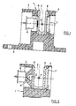
- the devices shown in the figures for measuring the cross section or the volume of a running thread F each have a housing 1 a measuring gap 2 through which the thread F to be measured runs.
- the exemplary embodiments shown show measuring devices with a measuring gap 2 of different width, which is approximately 2.5 mm in FIGS. 1 and 3, approximately 4 mm in FIG. 2 and approximately 6 mm in FIG. 4.
- the one-piece molded plastic housing 1 consists essentially of two side walls 3 and 4 surrounding the measuring gap 2, in which the optical and electronic parts of the device are arranged, and a base plate 5 supporting the side walls 3, 4, which with first and second Bores for fastening screws of the housing 1 or for the electrical connection lines of the electronic parts is provided.
- the measuring gap 2 is covered against the two side walls 3 and 4 of the housing 1 by a diffuser 8 and 9, respectively, whereby diffuse lighting is produced in the measuring gap 2, which also falls on the photodiode 7 as diffuse light.
- the diffusing screen 9 in front of the photodiode 7 can also be designed as a filter disk for shielding the ambient light, or it can simultaneously serve as a diffusing and filter disk.
- a thread F passing through the measuring gap 2 has a cross-sectional change resulting from a yarn defect, for example from a thick or a thin point
- the shading of the photodiode 7 changes and accordingly its output signal. Based on this change of the off
- the output signal of the photodiode 7 can either simply register the defect as such, or the running thread F can be stopped and the defect can be eliminated.
- the lenses 8 and 9 are formed by plates made of sintered ceramic, in the embodiments of FIGS. 2 and 4, the lens 8 is made of milk or opal glass and the disk 9 acting as a filter disk is made of filter glass.
- a measurement field 2 that is as homogeneous as possible must be present, that is, the illumination must be as homogeneous as possible and in all three coordinate directions.
- an aperture 10 is provided according to FIG the optical axis of the light emitting diode 6 is arranged and covers a certain area of the lens 8. The size of this area is chosen so that the peak value of the luminance is reduced to such an extent that it is adapted to the luminance outside this area.
- the peak of the luminance in the region of the optical axis is cut off by the diaphragm 10.
- the diaphragm 10 should have an area of approximately 4 mm 2.
- the aperture 10 can be formed by a plate in the shape of a regular surface, for example a circle, a polygon or an asterisk.
- the diaphragm 10 does not necessarily have to be flat, but can also be three-dimensional, for example as indicated by dashed lines in FIG. 1, as a spherical cap, or as a cone with the tip against the light-emitting diode 6, or as a cylinder, and the like.
- a light guide 11 is arranged between the light-emitting diode 6 and the diffusing screen 8, as a result of which the homogeneity of the illumination in the measuring gap 2 is improved.
- the light guide 11 consists of a suitable material such as glass or plexiglass and has the shape of a truncated cone. Its base surface lying against the lens 8 is provided with a suitable recess 12.
- the recess 12 is formed by a blind bore, the conical end with respect to its opening angle is matched to that of the light guide 11, in FIG. 3 by a conical depression with an opening angle of approximately 90 ° and in FIG. 4 by a conical depression with an opening angle of approximately 15 °. Further variations in the design of the depression 12 and also combinations of the exemplary embodiments shown are possible.
- the recess 12 could also be mirrored in the manner described in the exemplary embodiments in FIGS. 3 and 4, but on the other hand is in many cases mirroring is not absolutely necessary because the light emitted by the light-emitting diode 6 is concentrated in the light guide 11 anyway.
- the light covered by the aperture is not lost, but instead is stretched into measuring gap 2, which increases the output signal of photodiode 7, which in turn enables a reduction in the light-emitting diode current.
- the proportion of the light that enters the measuring gap 2 and is reflected by the diaphragm 12 can be increased further by mirroring the inside of the truncated cone-shaped light guide 11.
Applications Claiming Priority (2)
| Application Number | Priority Date | Filing Date | Title |
|---|---|---|---|
| CH188886A CH669615A5 (fr) | 1986-05-07 | 1986-05-07 | |
| CH1888/86 | 1986-05-07 |
Publications (3)
| Publication Number | Publication Date |
|---|---|
| EP0244788A2 true EP0244788A2 (fr) | 1987-11-11 |
| EP0244788A3 EP0244788A3 (en) | 1989-07-26 |
| EP0244788B1 EP0244788B1 (fr) | 1991-10-30 |
Family
ID=4220943
Family Applications (1)
| Application Number | Title | Priority Date | Filing Date |
|---|---|---|---|
| EP19870106356 Expired - Lifetime EP0244788B1 (fr) | 1986-05-07 | 1987-04-30 | Dispositif de mesure de la coupe en travers ou du volume d'un fil courant |
Country Status (4)
| Country | Link |
|---|---|
| EP (1) | EP0244788B1 (fr) |
| JP (1) | JPH0737888B2 (fr) |
| CH (1) | CH669615A5 (fr) |
| DE (1) | DE3774168D1 (fr) |
Cited By (5)
| Publication number | Priority date | Publication date | Assignee | Title |
|---|---|---|---|---|
| EP0401600A2 (fr) * | 1989-06-07 | 1990-12-12 | Zellweger Luwa Ag | Dispositif pour surveiller et/ou mesurer des paramètres d'un matériau en mouvement à contrôler en forme de fil textile ou métallique et méthode pour le fonctionnement du dispositif |
| EP1655600A2 (fr) | 2004-11-06 | 2006-05-10 | Saurer GmbH & Co. KG | Détecteur de fil |
| DE102008005706B4 (de) * | 2008-01-24 | 2011-08-25 | Carl Zeiss Meditec AG, 07745 | Medizingerät mit einer ringförmigen Beleuchtung |
| DE102013213523A1 (de) * | 2013-07-10 | 2015-01-15 | Bayerische Motoren Werke Aktiengesellschaft | Streuscheibe, Beleuchtungsvorrichtung und Kraftfahrzeug-Bauteil |
| EP3747812A1 (fr) * | 2019-06-06 | 2020-12-09 | Gebrüder Loepfe AG | Dispositif de capteur pour détecter la qualité d'un corps textile allongé |
Families Citing this family (3)
| Publication number | Priority date | Publication date | Assignee | Title |
|---|---|---|---|---|
| DE19858287A1 (de) * | 1998-12-17 | 2000-06-21 | Schlafhorst & Co W | Verfahren und Vorrichtung zur berührungslosen Garnüberwachung an einer Spinn- oder Spulmaschine |
| JP6984835B2 (ja) * | 2018-08-03 | 2021-12-22 | 株式会社豊田自動織機 | 繊維試料の評価方法及び繊維試料評価システム |
| JP2023120004A (ja) * | 2022-02-17 | 2023-08-29 | 村田機械株式会社 | 糸監視装置及び糸巻取機 |
Citations (3)
| Publication number | Priority date | Publication date | Assignee | Title |
|---|---|---|---|---|
| GB2077426A (en) * | 1980-05-30 | 1981-12-16 | Fuji Electric Co Ltd | Apparatus for measuring film thickness |
| JPS58158605A (ja) * | 1982-03-15 | 1983-09-20 | Stanley Electric Co Ltd | 光学ガイド装置 |
| DE2602465C2 (de) * | 1976-01-23 | 1984-08-30 | W. Schlafhorst & Co, 4050 Mönchengladbach | Vorrichtung zum Messen des Querschnittes oder Volumens eines laufenden Fadens |
-
1986
- 1986-05-07 CH CH188886A patent/CH669615A5/de not_active IP Right Cessation
-
1987
- 1987-04-30 EP EP19870106356 patent/EP0244788B1/fr not_active Expired - Lifetime
- 1987-04-30 DE DE8787106356T patent/DE3774168D1/de not_active Expired - Fee Related
- 1987-05-01 JP JP10650787A patent/JPH0737888B2/ja not_active Expired - Lifetime
Patent Citations (3)
| Publication number | Priority date | Publication date | Assignee | Title |
|---|---|---|---|---|
| DE2602465C2 (de) * | 1976-01-23 | 1984-08-30 | W. Schlafhorst & Co, 4050 Mönchengladbach | Vorrichtung zum Messen des Querschnittes oder Volumens eines laufenden Fadens |
| GB2077426A (en) * | 1980-05-30 | 1981-12-16 | Fuji Electric Co Ltd | Apparatus for measuring film thickness |
| JPS58158605A (ja) * | 1982-03-15 | 1983-09-20 | Stanley Electric Co Ltd | 光学ガイド装置 |
Non-Patent Citations (2)
| Title |
|---|
| FEINWERKTECHNIK UND MESSTECHNIK, Band 89, Heft 2, März 1981, Seiten 87-89, München, DE; H. BUSCHMANN: "Optische Wegmesssonde". * |
| PATENT ABSTRACTS OF JAPAN, Band 7, Nr. 282 (P-243)(1427) 16 Dezember 1983; & JP-A-58 158 605 (STANLEY DENKI K.K.) 20-09-1983 * |
Cited By (9)
| Publication number | Priority date | Publication date | Assignee | Title |
|---|---|---|---|---|
| EP0401600A2 (fr) * | 1989-06-07 | 1990-12-12 | Zellweger Luwa Ag | Dispositif pour surveiller et/ou mesurer des paramètres d'un matériau en mouvement à contrôler en forme de fil textile ou métallique et méthode pour le fonctionnement du dispositif |
| EP0401600A3 (fr) * | 1989-06-07 | 1992-10-21 | Zellweger Luwa Ag | Dispositif pour surveiller et/ou mesurer des paramètres d'un matériau en mouvement à contrôler en forme de fil textile ou métallique et méthode pour le fonctionnement du dispositif |
| EP1655600A2 (fr) | 2004-11-06 | 2006-05-10 | Saurer GmbH & Co. KG | Détecteur de fil |
| EP1655600A3 (fr) * | 2004-11-06 | 2006-06-28 | Saurer GmbH & Co. KG | Détecteur de fil |
| CN1769890B (zh) * | 2004-11-06 | 2010-11-03 | 欧瑞康纺织有限及两合公司 | 纱线探测装置 |
| DE102004053736B4 (de) * | 2004-11-06 | 2013-05-29 | Oerlikon Textile Gmbh & Co. Kg | Garnsensor |
| DE102008005706B4 (de) * | 2008-01-24 | 2011-08-25 | Carl Zeiss Meditec AG, 07745 | Medizingerät mit einer ringförmigen Beleuchtung |
| DE102013213523A1 (de) * | 2013-07-10 | 2015-01-15 | Bayerische Motoren Werke Aktiengesellschaft | Streuscheibe, Beleuchtungsvorrichtung und Kraftfahrzeug-Bauteil |
| EP3747812A1 (fr) * | 2019-06-06 | 2020-12-09 | Gebrüder Loepfe AG | Dispositif de capteur pour détecter la qualité d'un corps textile allongé |
Also Published As
| Publication number | Publication date |
|---|---|
| JPS62274207A (ja) | 1987-11-28 |
| CH669615A5 (fr) | 1989-03-31 |
| DE3774168D1 (de) | 1991-12-05 |
| EP0244788B1 (fr) | 1991-10-30 |
| EP0244788A3 (en) | 1989-07-26 |
| JPH0737888B2 (ja) | 1995-04-26 |
Similar Documents
| Publication | Publication Date | Title |
|---|---|---|
| EP0930600B1 (fr) | Elément optique ayant DEL et deux lentilles pour la génération des points de lumière pour panneaux de signalisation et d'affichage | |
| DE10330261B4 (de) | Fahrzeugleuchte | |
| DE60208934T2 (de) | Beleuchtungsvorrichtung und Flüssigkristallanzeige | |
| DE3701721A1 (de) | Remissionsmessgeraet zur beruehrungslosen messung | |
| DE2942655A1 (de) | Optische vorrichtung zum sammeln und streuen von licht | |
| DE3619538A1 (de) | Anordnung zum feststellen der vereisung | |
| CH657923A5 (de) | Anordnung zur erfassung von lichtboegen. | |
| DE3515809A1 (de) | Optisches beleuchtungssystem fuer ein endoskop | |
| EP1110031B1 (fr) | Lampe dotee d'un guide de lumiere | |
| DE3208753A1 (de) | Epidunkles beleuchtungssystem | |
| DE3300271C2 (de) | Beleuchtetes Anzeigeinstrument | |
| EP0244788B1 (fr) | Dispositif de mesure de la coupe en travers ou du volume d'un fil courant | |
| DE3818815A1 (de) | Remissionsmessgeraet | |
| DE102013219830B4 (de) | Optische Vorrichtung zur Reflexionsmessung unter diffuser Beleuchtung und Verfahren zum Optimieren einer solchen, sowie Verwendung der Vorrichtung | |
| WO1992020154A1 (fr) | Barrage photoelectrique a fourche | |
| DE3518832C2 (fr) | ||
| EP1574880A1 (fr) | Emetteur pour barrière lumineuse, rideau optique ou équivalent | |
| DE3033141C2 (de) | Lichtleiter in einem Anzeigetableau | |
| WO2018215435A2 (fr) | Capteur et biocapteur | |
| DE102017125212B4 (de) | Linse und leuchtmodul | |
| DE19615971A1 (de) | Lichtleiter für Meß- oder Beleuchtungseinrichtung | |
| DE2139865A1 (de) | Fuellstandsanzeiger oder zustandsdetektor | |
| EP0073879B1 (fr) | Dispositif pour le contrôle du titre d'un câble de fibres chimiques | |
| DE2602465A1 (de) | Vorrichtung zur messung des querschnittes oder volumens eines laufenden fadens | |
| DE102012222571A1 (de) | Optischer Winkeldetektor |
Legal Events
| Date | Code | Title | Description |
|---|---|---|---|
| PUAI | Public reference made under article 153(3) epc to a published international application that has entered the european phase |
Free format text: ORIGINAL CODE: 0009012 |
|
| AK | Designated contracting states |
Kind code of ref document: A2 Designated state(s): BE DE FR GB IT NL |
|
| PUAL | Search report despatched |
Free format text: ORIGINAL CODE: 0009013 |
|
| AK | Designated contracting states |
Kind code of ref document: A3 Designated state(s): BE DE FR GB IT NL |
|
| 17P | Request for examination filed |
Effective date: 19900109 |
|
| 17Q | First examination report despatched |
Effective date: 19901204 |
|
| ITF | It: translation for a ep patent filed |
Owner name: FIAMMENGHI - DOMENIGHETTI |
|
| GRAA | (expected) grant |
Free format text: ORIGINAL CODE: 0009210 |
|
| AK | Designated contracting states |
Kind code of ref document: B1 Designated state(s): BE DE FR GB IT NL |
|
| REF | Corresponds to: |
Ref document number: 3774168 Country of ref document: DE Date of ref document: 19911205 |
|
| GBT | Gb: translation of ep patent filed (gb section 77(6)(a)/1977) | ||
| ET | Fr: translation filed | ||
| PLBE | No opposition filed within time limit |
Free format text: ORIGINAL CODE: 0009261 |
|
| STAA | Information on the status of an ep patent application or granted ep patent |
Free format text: STATUS: NO OPPOSITION FILED WITHIN TIME LIMIT |
|
| 26N | No opposition filed | ||
| PGFP | Annual fee paid to national office [announced via postgrant information from national office to epo] |
Ref country code: FR Payment date: 19940411 Year of fee payment: 8 |
|
| PGFP | Annual fee paid to national office [announced via postgrant information from national office to epo] |
Ref country code: NL Payment date: 19940430 Year of fee payment: 8 |
|
| PG25 | Lapsed in a contracting state [announced via postgrant information from national office to epo] |
Ref country code: NL Effective date: 19951101 |
|
| PG25 | Lapsed in a contracting state [announced via postgrant information from national office to epo] |
Ref country code: FR Effective date: 19951229 |
|
| NLV4 | Nl: lapsed or anulled due to non-payment of the annual fee |
Effective date: 19951101 |
|
| REG | Reference to a national code |
Ref country code: FR Ref legal event code: ST |
|
| PGFP | Annual fee paid to national office [announced via postgrant information from national office to epo] |
Ref country code: GB Payment date: 19960422 Year of fee payment: 10 |
|
| PG25 | Lapsed in a contracting state [announced via postgrant information from national office to epo] |
Ref country code: GB Effective date: 19970430 |
|
| GBPC | Gb: european patent ceased through non-payment of renewal fee |
Effective date: 19970430 |
|
| PGFP | Annual fee paid to national office [announced via postgrant information from national office to epo] |
Ref country code: DE Payment date: 20010423 Year of fee payment: 15 |
|
| PGFP | Annual fee paid to national office [announced via postgrant information from national office to epo] |
Ref country code: BE Payment date: 20010625 Year of fee payment: 15 |
|
| PG25 | Lapsed in a contracting state [announced via postgrant information from national office to epo] |
Ref country code: BE Free format text: LAPSE BECAUSE OF NON-PAYMENT OF DUE FEES Effective date: 20020430 |
|
| PG25 | Lapsed in a contracting state [announced via postgrant information from national office to epo] |
Ref country code: DE Free format text: LAPSE BECAUSE OF NON-PAYMENT OF DUE FEES Effective date: 20021101 |
|
| PG25 | Lapsed in a contracting state [announced via postgrant information from national office to epo] |
Ref country code: IT Free format text: LAPSE BECAUSE OF NON-PAYMENT OF DUE FEES;WARNING: LAPSES OF ITALIAN PATENTS WITH EFFECTIVE DATE BEFORE 2007 MAY HAVE OCCURRED AT ANY TIME BEFORE 2007. THE CORRECT EFFECTIVE DATE MAY BE DIFFERENT FROM THE ONE RECORDED. Effective date: 20050430 |