EP0244788A2 - Device for measuring the cross section or the volume of a running thread - Google Patents
Device for measuring the cross section or the volume of a running thread Download PDFInfo
- Publication number
- EP0244788A2 EP0244788A2 EP87106356A EP87106356A EP0244788A2 EP 0244788 A2 EP0244788 A2 EP 0244788A2 EP 87106356 A EP87106356 A EP 87106356A EP 87106356 A EP87106356 A EP 87106356A EP 0244788 A2 EP0244788 A2 EP 0244788A2
- Authority
- EP
- European Patent Office
- Prior art keywords
- diaphragm
- light
- measuring
- measuring gap
- light source
- Prior art date
- Legal status (The legal status is an assumption and is not a legal conclusion. Google has not performed a legal analysis and makes no representation as to the accuracy of the status listed.)
- Granted
Links
Images

Classifications
-
- G—PHYSICS
- G01—MEASURING; TESTING
- G01B—MEASURING LENGTH, THICKNESS OR SIMILAR LINEAR DIMENSIONS; MEASURING ANGLES; MEASURING AREAS; MEASURING IRREGULARITIES OF SURFACES OR CONTOURS
- G01B11/00—Measuring arrangements characterised by the use of optical techniques
- G01B11/08—Measuring arrangements characterised by the use of optical techniques for measuring diameters
- G01B11/10—Measuring arrangements characterised by the use of optical techniques for measuring diameters of objects while moving
- G01B11/105—Measuring arrangements characterised by the use of optical techniques for measuring diameters of objects while moving using photoelectric detection means
-
- B—PERFORMING OPERATIONS; TRANSPORTING
- B65—CONVEYING; PACKING; STORING; HANDLING THIN OR FILAMENTARY MATERIAL
- B65H—HANDLING THIN OR FILAMENTARY MATERIAL, e.g. SHEETS, WEBS, CABLES
- B65H63/00—Warning or safety devices, e.g. automatic fault detectors, stop-motions ; Quality control of the package
- B65H63/06—Warning or safety devices, e.g. automatic fault detectors, stop-motions ; Quality control of the package responsive to presence of irregularities in running material, e.g. for severing the material at irregularities ; Control of the correct working of the yarn cleaner
- B65H63/062—Electronic slub detector
- B65H63/065—Electronic slub detector using photo-electric sensing means, i.e. the defect signal is a variation of light energy
-
- B—PERFORMING OPERATIONS; TRANSPORTING
- B65—CONVEYING; PACKING; STORING; HANDLING THIN OR FILAMENTARY MATERIAL
- B65H—HANDLING THIN OR FILAMENTARY MATERIAL, e.g. SHEETS, WEBS, CABLES
- B65H2701/00—Handled material; Storage means
- B65H2701/30—Handled filamentary material
- B65H2701/31—Textiles threads or artificial strands of filaments
Definitions
- the invention relates to a device for measuring the cross-section or the volume of a running thread, with a measuring gap, on one side of which a diffuser which is illuminated transversely by a light source from the side facing away from the measuring gap and partially covered by a diaphragm and on the other side of which Photoelectric element is arranged, the output signal represents a measure of the cross section and / or the volume of the running thread.
- the lens in order to achieve a more precise measurement result, in particular in the case of an oscillating thread, the lens is designed such that it is measured parallel to the thread and has a width that decreases here towards the center of the surface. If the thread changes from the center to the edges of the lens, it covers the lens with a greater length than in the center of the lens, where the luminance is greater. As a result, the effect of shading the photoelectric element is always the same regardless of the respective position of the thread in the traversing area. Reducing the width the lens is created by two saddles on the top and bottom edge or by a segment-like screen.
- a measuring field that is as homogeneous as possible must exist within the measuring gap, with homogeneity in all three coordinate directions.
- good homogeneity is achieved in the spreading disc plane perpendicular to the thread running direction, but the measuring field in the thread running direction is not homogeneous because of the saddle or aperture extending over the entire spreading disc.
- the latter causes a certain measurement inaccuracy, which leads in particular to yarn errors that are shorter than the corresponding measurement field length, to disturbing and intolerable measurement errors.
- Such yarn defects are, for example, short thick spots.
- the invention is based on the object of producing a measurement field which is as homogeneous as possible in the measurement gap and which has good homogeneity in particular in the thread running direction and thus enables an accurate measurement result even with running and changing threads with short yarn errors, such as short thick spots.
- the diaphragm is arranged in the optical axis of the light source and covers an area of the lens surrounding this optical axis in such a way that the luminance in the corresponding area in the measuring gap is adapted to the value prevailing outside this area.
- a light-guiding element surrounding the screen is arranged between the light source and the lens. This embodiment has the advantage of further improving the homogeneity of the measuring field.
- the diaphragm is designed to be reflective on its surface facing the light source and the light-conducting element deflects the light component reflecting from the diaphragm to the diffusing screen.
- This embodiment has the advantage that the light covered by the diaphragm is not lost, but rather gets into the measuring gap, which leads to an increase in the value of the measuring signal and thus allows a reduction in the current of the light source.
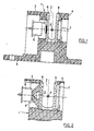
- the devices shown in the figures for measuring the cross section or the volume of a running thread F each have a housing 1 a measuring gap 2 through which the thread F to be measured runs.
- the exemplary embodiments shown show measuring devices with a measuring gap 2 of different width, which is approximately 2.5 mm in FIGS. 1 and 3, approximately 4 mm in FIG. 2 and approximately 6 mm in FIG. 4.
- the one-piece molded plastic housing 1 consists essentially of two side walls 3 and 4 surrounding the measuring gap 2, in which the optical and electronic parts of the device are arranged, and a base plate 5 supporting the side walls 3, 4, which with first and second Bores for fastening screws of the housing 1 or for the electrical connection lines of the electronic parts is provided.
- the measuring gap 2 is covered against the two side walls 3 and 4 of the housing 1 by a diffuser 8 and 9, respectively, whereby diffuse lighting is produced in the measuring gap 2, which also falls on the photodiode 7 as diffuse light.
- the diffusing screen 9 in front of the photodiode 7 can also be designed as a filter disk for shielding the ambient light, or it can simultaneously serve as a diffusing and filter disk.
- a thread F passing through the measuring gap 2 has a cross-sectional change resulting from a yarn defect, for example from a thick or a thin point
- the shading of the photodiode 7 changes and accordingly its output signal. Based on this change of the off
- the output signal of the photodiode 7 can either simply register the defect as such, or the running thread F can be stopped and the defect can be eliminated.
- the lenses 8 and 9 are formed by plates made of sintered ceramic, in the embodiments of FIGS. 2 and 4, the lens 8 is made of milk or opal glass and the disk 9 acting as a filter disk is made of filter glass.
- a measurement field 2 that is as homogeneous as possible must be present, that is, the illumination must be as homogeneous as possible and in all three coordinate directions.
- an aperture 10 is provided according to FIG the optical axis of the light emitting diode 6 is arranged and covers a certain area of the lens 8. The size of this area is chosen so that the peak value of the luminance is reduced to such an extent that it is adapted to the luminance outside this area.
- the peak of the luminance in the region of the optical axis is cut off by the diaphragm 10.
- the diaphragm 10 should have an area of approximately 4 mm 2.
- the aperture 10 can be formed by a plate in the shape of a regular surface, for example a circle, a polygon or an asterisk.
- the diaphragm 10 does not necessarily have to be flat, but can also be three-dimensional, for example as indicated by dashed lines in FIG. 1, as a spherical cap, or as a cone with the tip against the light-emitting diode 6, or as a cylinder, and the like.
- a light guide 11 is arranged between the light-emitting diode 6 and the diffusing screen 8, as a result of which the homogeneity of the illumination in the measuring gap 2 is improved.
- the light guide 11 consists of a suitable material such as glass or plexiglass and has the shape of a truncated cone. Its base surface lying against the lens 8 is provided with a suitable recess 12.
- the recess 12 is formed by a blind bore, the conical end with respect to its opening angle is matched to that of the light guide 11, in FIG. 3 by a conical depression with an opening angle of approximately 90 ° and in FIG. 4 by a conical depression with an opening angle of approximately 15 °. Further variations in the design of the depression 12 and also combinations of the exemplary embodiments shown are possible.
- the recess 12 could also be mirrored in the manner described in the exemplary embodiments in FIGS. 3 and 4, but on the other hand is in many cases mirroring is not absolutely necessary because the light emitted by the light-emitting diode 6 is concentrated in the light guide 11 anyway.
- the light covered by the aperture is not lost, but instead is stretched into measuring gap 2, which increases the output signal of photodiode 7, which in turn enables a reduction in the light-emitting diode current.
- the proportion of the light that enters the measuring gap 2 and is reflected by the diaphragm 12 can be increased further by mirroring the inside of the truncated cone-shaped light guide 11.
Abstract
Description
Die Erfindung betrifft eine Vorrichtung zur Messung des Querschnitts oder des Volumens eines laufenden Fadens, mit einem Messspalt, an dessen einer Seite eine von der dem Messspalt abgewandten Seite her quer durch eine Lichtquelle beleuchtete und durch eine Blende teilweise abgedeckte Streuscheibe und an dessen anderer Seite ein fotoelektrisches Element angeordnet ist, dessen Ausgangssignal ein Mass für den Querschnitt und/oder das Volumen des laufenden Fadens darstellt.The invention relates to a device for measuring the cross-section or the volume of a running thread, with a measuring gap, on one side of which a diffuser which is illuminated transversely by a light source from the side facing away from the measuring gap and partially covered by a diaphragm and on the other side of which Photoelectric element is arranged, the output signal represents a measure of the cross section and / or the volume of the running thread.
Bei einer aus der DE-PS 26 02 465 bekannten Vorrichtung dieser Art, ist zur Erzielung eines genaueren Messergebnisses, insbeosndere bei einem changierenden Faden, die Streuscheibe so ausgebildet, dass sie parallel zum Faden gemessen, eine zur Flächenmitte hier abnehmenden Breite besitzt. Wenn der Faden von der Mitte aus zu den Rändern der Streuscheibe hin changiert, überdeckt er die Streuscheibe mit einer grösseren Länge als in der Streuscheibenmitte, wo die Leuchtdichte grösser ist. Dadurch ist der Effekt der Abschattung des fotoelektrischen Elements unabhängig von der jeweiligen Lage des Fadens im Changierbereich immer gleich. Die Verringerung der Breite der Streuscheibe wird durch zwei Einsattelungen an deren oberem und unterem Rand oder durch eine segmentähnliche Blende bewirkt.In a device of this type known from DE-PS 26 02 465, in order to achieve a more precise measurement result, in particular in the case of an oscillating thread, the lens is designed such that it is measured parallel to the thread and has a width that decreases here towards the center of the surface. If the thread changes from the center to the edges of the lens, it covers the lens with a greater length than in the center of the lens, where the luminance is greater. As a result, the effect of shading the photoelectric element is always the same regardless of the respective position of the thread in the traversing area. Reducing the width the lens is created by two saddles on the top and bottom edge or by a segment-like screen.
Bei derartigen Messvorrichtung muss innerhalb des Messspalts ein möglichst homogenes Messfeld bestehen und zwar mit Homogenität in allen drei Koordinatenrichtungen. Bei der genannten bekannten Vorrichtung wird zwar in der Streuscheibenebene senkrecht zur Fadenlaufrichtung eine gute Homogenität erreicht, dafür ist aber das Messfeld in Fadenlaufrichtung wegen der über die ganze Streuscheibe reichenden Einsattelung oder Blende nicht homogen. Letzteres verursacht eine gewisse Messungenauigkeit, welche insbesondere bei Garnfehlern, die kürzer sind als die entsprechende Messfeldlänge, zu störenden und nicht tolerierbaren Messfehlern führt. Derartige Garnfehler sind beispielsweise kurze Dickstellen.In the case of such a measuring device, a measuring field that is as homogeneous as possible must exist within the measuring gap, with homogeneity in all three coordinate directions. In the known device mentioned, good homogeneity is achieved in the spreading disc plane perpendicular to the thread running direction, but the measuring field in the thread running direction is not homogeneous because of the saddle or aperture extending over the entire spreading disc. The latter causes a certain measurement inaccuracy, which leads in particular to yarn errors that are shorter than the corresponding measurement field length, to disturbing and intolerable measurement errors. Such yarn defects are, for example, short thick spots.
Der Erfindung liegt nun die Aufgabe zugrunde, im Messspalt ein möglichst homogenes Messfeld zu erzeugen, welches insbesondere auch in Fadenlaufrichtung eine gute Homogenität aufweist und damit auch bei laufenden und changierenden Fäden mit kurzen Garnfehlern, wie beispielsweise kurzen Dickstellen, ein genaues Messergebnis ermöglicht.The invention is based on the object of producing a measurement field which is as homogeneous as possible in the measurement gap and which has good homogeneity in particular in the thread running direction and thus enables an accurate measurement result even with running and changing threads with short yarn errors, such as short thick spots.
Diese Aufgabe wird erfindungsgemäss dadurch gelöst, dass die Blende in der optischen Achse der Lichtquelle angeordnet ist und einen diese optische Achse umgebenden Bereich der Streuscheibe so abdeckt, dass im entsprechenden Bereich im Messspalt die Leuchtdichte an den ausserhalb dieses Bereichs herrschenden Wert angepasst ist.This object is achieved according to the invention in that the diaphragm is arranged in the optical axis of the light source and covers an area of the lens surrounding this optical axis in such a way that the luminance in the corresponding area in the measuring gap is adapted to the value prevailing outside this area.
Praktische Versuche haben gezeigt, dass mit der erfindungsgemässen Lösung im Messspalt ein in allen Koordinatenrichtungen homogenes Messfeld erzielt wird, und dass das Messsignal auch bei kurzen Garnfehlern genau und reproduzierbar ist.Practical tests have shown that the solution according to the invention achieves a measuring field which is homogeneous in all coordinate directions and that the measuring signal is accurate and reproducible even with short yarn errors.
Gemäss einer ersten bevorzugten Ausführungsform der erfindungsgemässen Vorrichtung ist zwischen Lichtquelle und Streuscheibe ein die Blende umgebendes lichtleitendes Element angeordnet. Diese Ausführungsform hat den Vorteil einer nochmaligen Verbesserung der Homogenität des Messfelds.According to a first preferred embodiment of the device according to the invention, a light-guiding element surrounding the screen is arranged between the light source and the lens. This embodiment has the advantage of further improving the homogeneity of the measuring field.
Gemäss einer zweiten bevorzugten Ausführungsform der erfindungsgemässen Vorrichtung ist die Blende an ihrer der Lichtquelle zugewandten Oberfläche reflektierend ausgebildet und erfolgt durch das lichtleitende Element eine Umlenkung des von der Blende reflektierenden Lichtanteils an die Streuscheibe. Diese Ausführungsform hat den Vorteil, dass das von der Blende abgedeckte Licht nicht verlorengeht, sondern in den Messspalt gelangt, was zu einer Erhöhung des Werts des Messignals führt und damit eine Verringerung des Stroms der Lichtquelle erlaubt.According to a second preferred embodiment of the device according to the invention, the diaphragm is designed to be reflective on its surface facing the light source and the light-conducting element deflects the light component reflecting from the diaphragm to the diffusing screen. This embodiment has the advantage that the light covered by the diaphragm is not lost, but rather gets into the measuring gap, which leads to an increase in the value of the measuring signal and thus allows a reduction in the current of the light source.
Im folgenden wird die Erfindung anhand von Ausführungsbeispielen und der Zeichnungen näher erläutert; es zeigen:
- Fig. 1 bis 4 je eine Schnittdarstellung eines Ausführungsbeispiels einer erfindungsgemässen Vorrichtung in vergrössertem Massstab.
- 1 to 4 each show a sectional view of an embodiment of a device according to the invention on an enlarged scale.
Die in den Figuren dargestellten Vorrichtungen zur Messung der Querschnitts oder des Volumens eines laufenden Fadens F weisen je ein Gehäuse 1 mit einem Messspalt 2 auf, durch welchen der zu vermessende Faden F läuft. Die dargestellten Ausführungsbeispiele zeigen Messvorrichtungen mit verschieden breitem Messspalt 2, welcher in den Figuren 1 und 3 etwa 2,5 mm, in Fig. 2 etwa 4 mm und in Fig. 4 etwa 6 mm breit ist.The devices shown in the figures for measuring the cross section or the volume of a running thread F each have a housing 1 a
Das einstückig aus Kunststoff gespritzte Gehäuse 1 besteht im wesentlichen aus zwei den Messspalt 2 umgebenden Seitenwänden 3 und 4, in denen die optischen und elektronischen Teile der Vorrichtung angeordnet sind, und aus einer die Seitenwände 3, 4 tragenden Grundplatte 5, welche mit ersten und zweiten Bohrungen für Befestigungsschrauben des Gehäuses 1 bzw. für die elektrischen Anschlussleitungen der elektronischen Teile versehen ist.The one-piece molded
In der in den Figuren linken Seitenwand ist eine Lichtquelle 6, vorzugsweise eine Leuchtdiode angeordnet, welche Licht in Richtung auf eine in der rechten Seitenwand 4 angeordnete, vorzugsweise in dieser eingegossene, Fotodiode 7 aussendet. Der Messspalt 2 ist gegen die beiden Seitenwände 3 und 4 des Gehäuses 1 hin je durch eine Streuscheibe 8 bzw. 9 abgedeckt, wodurch im Messspalt 2 eine diffuse Beleuchtung entsteht, welche auch als diffuses Licht auf die Fotodiode 7 fällt. Die Streuscheibe 9 vor der Fotodiode 7 kann auch als Filterscheibe zur Abschirmung des Umgebungslichts ausgebildet sein oder sie kann gleichzeitig als Streu- und als Filterscheibe dienen.A
Wenn ein den Messspalt 2 durchlaufender Faden F eine von einem Garnfehler, beispielsweise von einer Dick- oder einer Dünnstelle herrührende Querschnittsänderung aufweist, dann ändert sich die Abschattung der Fotodiode 7 und dementsprechend deren Ausgangssignal. Anhand dieser Aenderung des Aus gangssignals der Fotodiode 7 kann nun entweder die Fehlstelle als solche bloss registriert, oder kann der laufende Faden F angehalten und die Fehlstelle beseitigt werden.If a thread F passing through the
Für die Streuscheiben 8 und 9 haben sich verschiedene Materialien als geeignet erwiesen. Bei den Ausführungsbeispielen der Fig. 1 und 3 sind die Streuscheiben 8 und 9 durch Plättchen aus Sinterkeramik gebildet, bei den Ausführungsbeispielen der Fig. 2 und 4 ist die Streuscheibe 8 aus Milch- oder Opalglas und die als Filterscheibe wirkende Scheibe 9 ist aus Filterglas.Various materials have proven to be suitable for the
Damit das Ausgangssignal der Fotodiode 7 aussagekräftig und reproduzierbar ist, muss im Messspalt 2 ein möglichst homogenes Messfeld herrschen, das heisst, die Beleuchtung muss möglichst homogen sein und zwar in allen drei Koordinatenrichtungen. In der Richtung quer und parallel zum Messspalt 2, das sind die beiden Richtungen senkrecht zur Fadenlaufrichtung, wegen der Changierbewegung des Fadens F oder des Fehlerquerschnitts, und in Fadenlaufrichtung, damit relativ zur Messfeldlänge kurze Garnfehler unabhängig von der Position des Fadens F relativ zur optischen Achse das gleiche Ausgangssignal der Fotodiode 7 bewirken.So that the output signal of the
Dieser Forderung steht aber die bekannte Tatsache entgegen, dass trotz Verwendung der Streuscheibe 8 im Messspalt 2 im Bereich der optischen Achse eine grössere Leuchtdichte herrscht als ausserhalb dieses Bereichs. Zur Anpassung der Leuchtdichte im Bereich der optischen Achse an den Wert ausserhalb dieses Bereichs ist gemäss Fig. 1 eine Blende 10 vorgesehen, welche in der optischen Achse der Leuchtdiode 6 angeordnet ist und einen gewissen Bereich der Streuscheibe 8 abdeckt. Die Grösse dieses Bereichs ist so gewählt, dass der Spitzenwert der Leuchtdichte gerade so weit reduziert wird, dass er an die Leuchtdichte ausserhalb dieses Bereichs angepasst ist.However, this requirement is countered by the known fact that, despite the use of the diffusing
Durch die Blende 10 wird also mit anderen Worten die Spitze der Leuchtdichte im Bereich der optischen Achse abgeschnitten. Praktische Versuche haben ergeben, dass bei der in Fig. 1 dargestellten Breite des Messspalts 2 von etwa 2,5 mm die Blende 10 einen Flächeninhalt von etwa 4 mm2 aufweisen soll. Die Blende 10 kann dabei durch ein Plättchen von der Gestalt einer regelmässigen Fläche, beispielsweise eines Kreises, eines Vielecks oder auch eines Sternchens gebildet sein.In other words, the peak of the luminance in the region of the optical axis is cut off by the
Die Blende 10 braucht nicht unbedingt flächenhaft, sondern kann auch dreidimensional ausgebildet sein, beispielsweise so wie in Fig. 1 gestrichelt angedeutet, als Kugelkalotte, oder als Kegel mit der Spitze gegen die Leuchtdiode 6, oder als Zylinder, und dergleichen.The
Bei den in den Figuren 2 bis 4 dargestellten Ausführungsbeispielen ist zwischen der Leuchtdiode 6 und der Streuscheibe 8 ein Lichtleiter 11 angeordnet, wodurch die Homogenität der Beleuchtung im Messspalt 2 verbessert wird. Der Lichtleiter 11 besteht aus einem geeigneten Material wie Glas oder Plexiglas und weist die Form eines Kegelstumpfs auf. Seine an der Streuscheibe 8 anliegende Basisfläche ist mit einer geeigneten Vertiefung 12 versehen. In Fig. 2 ist die Vertiefung 12 durch eine Sackbohrung gebildet, deren kegelförmiger Abschluss bezüglich seines Oeffnungswinkels an denjenigen des Lichtleiters 11 angepasst ist, in Fig. 3 durch eine kegelförmige Vertiefung mit einem Oeffnungswinkel von etwa 90° und in Fig. 4 durch eine kegelförmige Vertiefung mit einem Oeffnungswinkel von etwa 15°. Weitere Variationen der Ausbildung der Vertiefung 12 sowie auch Kombinationen der dargestellten Ausführungsbeispiele sind möglich.In the exemplary embodiments shown in FIGS. 2 to 4, a
Die die Vertiefung 12 bildende Sackbohrung von Fig. 2 ist an der Aussenfläche ihres kegelförmigen Teils verspiegelt und wirkt somit einerseits als Blende und reflektiert anderseits das auftreffende Licht in den Lichtleiter 11. Dieses von der "Blende" 12 reflektierte Licht wird bei geeigneter Wahl des Oeffnungswinkels des kegelstumpfförmigen Lichtleiters 11 (darstellungsgemäss etwa 45°) an dessen Mantel totalreflektiert und gelangt somit in den Messspalt 2. Selbstverständlich könnte auch bei den Ausführungsbeispielen der Fig. 3 und 4 die Vertiefung 12 in der beschriebenen Weise verspiegelt sein, anderseits ist aber in vielen Fällen eine Verspiegelung nicht unbedingt erforderlich, weil das von der Leuchtdiode 6 ausgesandte Licht ohnehin im Lichtleiter 11 konzentriert ist.2 is mirrored on the outer surface of its conical part and thus acts on the one hand as a diaphragm and on the other hand reflects the incident light into the
Durch die dargestellte Ausbildung von Lichtleiter 11 und "Blende" 12 geht also das von der Blende abgedeckte Licht nicht verloren, sondern gealngt in den Messspalt 2, wodurch das Ausgangssignal der Fotodiode 7 erhöht wird, was wiederum eine Verringerung des Leuchtdioden-Stroms ermöglicht. Der Anteil des in den Messspalt 2 gelangenden, von der Blende 12 reflektierten Lichtes kann noch dadurch erhöht werden, dass der Mantel des kegelstumpfförmigen Lichtleiter 11 innenverspiegelt wird.Due to the illustrated configuration of
Claims (9)
Applications Claiming Priority (2)
| Application Number | Priority Date | Filing Date | Title |
|---|---|---|---|
| CH1888/86 | 1986-05-07 | ||
| CH188886A CH669615A5 (en) | 1986-05-07 | 1986-05-07 |
Publications (3)
| Publication Number | Publication Date |
|---|---|
| EP0244788A2 true EP0244788A2 (en) | 1987-11-11 |
| EP0244788A3 EP0244788A3 (en) | 1989-07-26 |
| EP0244788B1 EP0244788B1 (en) | 1991-10-30 |
Family
ID=4220943
Family Applications (1)
| Application Number | Title | Priority Date | Filing Date |
|---|---|---|---|
| EP19870106356 Expired - Lifetime EP0244788B1 (en) | 1986-05-07 | 1987-04-30 | Device for measuring the cross section or the volume of a running thread |
Country Status (4)
| Country | Link |
|---|---|
| EP (1) | EP0244788B1 (en) |
| JP (1) | JPH0737888B2 (en) |
| CH (1) | CH669615A5 (en) |
| DE (1) | DE3774168D1 (en) |
Cited By (5)
| Publication number | Priority date | Publication date | Assignee | Title |
|---|---|---|---|---|
| EP0401600A2 (en) * | 1989-06-07 | 1990-12-12 | Zellweger Luwa Ag | Device for monitoring and/or measuring parameters of running test materials in form of thread or wire and method for operating the device |
| EP1655600A2 (en) | 2004-11-06 | 2006-05-10 | Saurer GmbH & Co. KG | Yarn sensor |
| DE102008005706B4 (en) * | 2008-01-24 | 2011-08-25 | Carl Zeiss Meditec AG, 07745 | Medical device with an annular illumination |
| DE102013213523A1 (en) * | 2013-07-10 | 2015-01-15 | Bayerische Motoren Werke Aktiengesellschaft | Diffuser, lighting device and motor vehicle component |
| EP3747812A1 (en) * | 2019-06-06 | 2020-12-09 | Gebrüder Loepfe AG | Sensor device for sensing the quality of an elongate textile body |
Families Citing this family (3)
| Publication number | Priority date | Publication date | Assignee | Title |
|---|---|---|---|---|
| DE19858287A1 (en) | 1998-12-17 | 2000-06-21 | Schlafhorst & Co W | Method and device for non-contact yarn monitoring on a spinning or winding machine |
| WO2020027295A1 (en) * | 2018-08-03 | 2020-02-06 | 株式会社豊田自動織機 | Fiber sample evaluation method and fiber sample evaluation system |
| JP2023120004A (en) * | 2022-02-17 | 2023-08-29 | 村田機械株式会社 | Yarn monitoring device and yarn winder |
Citations (3)
| Publication number | Priority date | Publication date | Assignee | Title |
|---|---|---|---|---|
| GB2077426A (en) * | 1980-05-30 | 1981-12-16 | Fuji Electric Co Ltd | Apparatus for measuring film thickness |
| JPS58158605A (en) * | 1982-03-15 | 1983-09-20 | Stanley Electric Co Ltd | Light guide device |
| DE2602465C2 (en) * | 1976-01-23 | 1984-08-30 | W. Schlafhorst & Co, 4050 Mönchengladbach | Device for measuring the cross-section or volume of a running thread |
-
1986
- 1986-05-07 CH CH188886A patent/CH669615A5/de not_active IP Right Cessation
-
1987
- 1987-04-30 EP EP19870106356 patent/EP0244788B1/en not_active Expired - Lifetime
- 1987-04-30 DE DE8787106356T patent/DE3774168D1/en not_active Expired - Fee Related
- 1987-05-01 JP JP10650787A patent/JPH0737888B2/en not_active Expired - Lifetime
Patent Citations (3)
| Publication number | Priority date | Publication date | Assignee | Title |
|---|---|---|---|---|
| DE2602465C2 (en) * | 1976-01-23 | 1984-08-30 | W. Schlafhorst & Co, 4050 Mönchengladbach | Device for measuring the cross-section or volume of a running thread |
| GB2077426A (en) * | 1980-05-30 | 1981-12-16 | Fuji Electric Co Ltd | Apparatus for measuring film thickness |
| JPS58158605A (en) * | 1982-03-15 | 1983-09-20 | Stanley Electric Co Ltd | Light guide device |
Non-Patent Citations (2)
| Title |
|---|
| FEINWERKTECHNIK UND MESSTECHNIK, Band 89, Heft 2, März 1981, Seiten 87-89, München, DE; H. BUSCHMANN: "Optische Wegmesssonde". * |
| PATENT ABSTRACTS OF JAPAN, Band 7, Nr. 282 (P-243)(1427) 16 Dezember 1983; & JP-A-58 158 605 (STANLEY DENKI K.K.) 20-09-1983 * |
Cited By (9)
| Publication number | Priority date | Publication date | Assignee | Title |
|---|---|---|---|---|
| EP0401600A2 (en) * | 1989-06-07 | 1990-12-12 | Zellweger Luwa Ag | Device for monitoring and/or measuring parameters of running test materials in form of thread or wire and method for operating the device |
| EP0401600A3 (en) * | 1989-06-07 | 1992-10-21 | Zellweger Luwa Ag | Device for monitoring and/or measuring parameters of running test materials in form of thread or wire and method for operating the device |
| EP1655600A2 (en) | 2004-11-06 | 2006-05-10 | Saurer GmbH & Co. KG | Yarn sensor |
| EP1655600A3 (en) * | 2004-11-06 | 2006-06-28 | Saurer GmbH & Co. KG | Yarn sensor |
| CN1769890B (en) * | 2004-11-06 | 2010-11-03 | 欧瑞康纺织有限及两合公司 | Yarn detection device |
| DE102004053736B4 (en) * | 2004-11-06 | 2013-05-29 | Oerlikon Textile Gmbh & Co. Kg | yarn sensor |
| DE102008005706B4 (en) * | 2008-01-24 | 2011-08-25 | Carl Zeiss Meditec AG, 07745 | Medical device with an annular illumination |
| DE102013213523A1 (en) * | 2013-07-10 | 2015-01-15 | Bayerische Motoren Werke Aktiengesellschaft | Diffuser, lighting device and motor vehicle component |
| EP3747812A1 (en) * | 2019-06-06 | 2020-12-09 | Gebrüder Loepfe AG | Sensor device for sensing the quality of an elongate textile body |
Also Published As
| Publication number | Publication date |
|---|---|
| JPS62274207A (en) | 1987-11-28 |
| JPH0737888B2 (en) | 1995-04-26 |
| DE3774168D1 (en) | 1991-12-05 |
| EP0244788B1 (en) | 1991-10-30 |
| EP0244788A3 (en) | 1989-07-26 |
| CH669615A5 (en) | 1989-03-31 |
Similar Documents
| Publication | Publication Date | Title |
|---|---|---|
| EP0930600B1 (en) | Optical element comprising LED and two lenses for the generation of pointlike light sources for traffic signs and display panels | |
| DE10330261B4 (en) | vehicle light | |
| DE60208934T2 (en) | Lighting device and liquid crystal display | |
| DE3701721A1 (en) | REMISSION MEASURING DEVICE FOR CONTACTLESS MEASUREMENT | |
| DE2942655A1 (en) | OPTICAL DEVICE FOR COLLECTING AND SCATTERING LIGHT | |
| DE3619538A1 (en) | DEVICE DETECTING ARRANGEMENT | |
| DE3515809A1 (en) | Optical illuminating system for an endoscope | |
| DE3208753A1 (en) | EPIDUNKLE LIGHTING SYSTEM | |
| EP1110031A1 (en) | Light with a light-guiding element | |
| DE3300271C2 (en) | Illuminated display instrument | |
| EP0244788B1 (en) | Device for measuring the cross section or the volume of a running thread | |
| DE102013219830B4 (en) | Optical device for reflection measurement under diffuse lighting and method for optimizing such, and use of the device | |
| WO1992020154A1 (en) | Forked light barrier | |
| EP1577608A2 (en) | Lamp with an optical structure for influencing the radiation | |
| DE3518832C2 (en) | ||
| CH402461A (en) | Electro-optical thread cleaner | |
| EP1574880A1 (en) | Emitter for light barrier, light curtain or similar | |
| DE3033141C2 (en) | Light guide in a display panel | |
| WO2018215435A2 (en) | Sensor and biosensor | |
| DE102017125212B4 (en) | LENS AND LIGHT MODULE | |
| DE19615971A1 (en) | Optical light guiding head made in glass or plastic | |
| DE2139865A1 (en) | LEVEL INDICATOR OR CONDITION DETECTOR | |
| EP0073879B1 (en) | Titercontrol device on spin cables from chemical fibres | |
| DE2602465A1 (en) | DEVICE FOR MEASURING THE SECTION OR VOLUME OF A RUNNING THREAD | |
| DE102012222571A1 (en) | Optical angle detector |
Legal Events
| Date | Code | Title | Description |
|---|---|---|---|
| PUAI | Public reference made under article 153(3) epc to a published international application that has entered the european phase |
Free format text: ORIGINAL CODE: 0009012 |
|
| AK | Designated contracting states |
Kind code of ref document: A2 Designated state(s): BE DE FR GB IT NL |
|
| PUAL | Search report despatched |
Free format text: ORIGINAL CODE: 0009013 |
|
| AK | Designated contracting states |
Kind code of ref document: A3 Designated state(s): BE DE FR GB IT NL |
|
| 17P | Request for examination filed |
Effective date: 19900109 |
|
| 17Q | First examination report despatched |
Effective date: 19901204 |
|
| ITF | It: translation for a ep patent filed |
Owner name: FIAMMENGHI - DOMENIGHETTI |
|
| GRAA | (expected) grant |
Free format text: ORIGINAL CODE: 0009210 |
|
| AK | Designated contracting states |
Kind code of ref document: B1 Designated state(s): BE DE FR GB IT NL |
|
| REF | Corresponds to: |
Ref document number: 3774168 Country of ref document: DE Date of ref document: 19911205 |
|
| GBT | Gb: translation of ep patent filed (gb section 77(6)(a)/1977) | ||
| ET | Fr: translation filed | ||
| PLBE | No opposition filed within time limit |
Free format text: ORIGINAL CODE: 0009261 |
|
| STAA | Information on the status of an ep patent application or granted ep patent |
Free format text: STATUS: NO OPPOSITION FILED WITHIN TIME LIMIT |
|
| 26N | No opposition filed | ||
| PGFP | Annual fee paid to national office [announced via postgrant information from national office to epo] |
Ref country code: FR Payment date: 19940411 Year of fee payment: 8 |
|
| PGFP | Annual fee paid to national office [announced via postgrant information from national office to epo] |
Ref country code: NL Payment date: 19940430 Year of fee payment: 8 |
|
| PG25 | Lapsed in a contracting state [announced via postgrant information from national office to epo] |
Ref country code: NL Effective date: 19951101 |
|
| PG25 | Lapsed in a contracting state [announced via postgrant information from national office to epo] |
Ref country code: FR Effective date: 19951229 |
|
| NLV4 | Nl: lapsed or anulled due to non-payment of the annual fee |
Effective date: 19951101 |
|
| REG | Reference to a national code |
Ref country code: FR Ref legal event code: ST |
|
| PGFP | Annual fee paid to national office [announced via postgrant information from national office to epo] |
Ref country code: GB Payment date: 19960422 Year of fee payment: 10 |
|
| PG25 | Lapsed in a contracting state [announced via postgrant information from national office to epo] |
Ref country code: GB Effective date: 19970430 |
|
| GBPC | Gb: european patent ceased through non-payment of renewal fee |
Effective date: 19970430 |
|
| PGFP | Annual fee paid to national office [announced via postgrant information from national office to epo] |
Ref country code: DE Payment date: 20010423 Year of fee payment: 15 |
|
| PGFP | Annual fee paid to national office [announced via postgrant information from national office to epo] |
Ref country code: BE Payment date: 20010625 Year of fee payment: 15 |
|
| PG25 | Lapsed in a contracting state [announced via postgrant information from national office to epo] |
Ref country code: BE Free format text: LAPSE BECAUSE OF NON-PAYMENT OF DUE FEES Effective date: 20020430 |
|
| PG25 | Lapsed in a contracting state [announced via postgrant information from national office to epo] |
Ref country code: DE Free format text: LAPSE BECAUSE OF NON-PAYMENT OF DUE FEES Effective date: 20021101 |
|
| PG25 | Lapsed in a contracting state [announced via postgrant information from national office to epo] |
Ref country code: IT Free format text: LAPSE BECAUSE OF NON-PAYMENT OF DUE FEES;WARNING: LAPSES OF ITALIAN PATENTS WITH EFFECTIVE DATE BEFORE 2007 MAY HAVE OCCURRED AT ANY TIME BEFORE 2007. THE CORRECT EFFECTIVE DATE MAY BE DIFFERENT FROM THE ONE RECORDED. Effective date: 20050430 |