EP0244657A1 - Selektiv abisolierter Koaxialsteckverbinder - Google Patents
Selektiv abisolierter Koaxialsteckverbinder Download PDFInfo
- Publication number
- EP0244657A1 EP0244657A1 EP87105176A EP87105176A EP0244657A1 EP 0244657 A1 EP0244657 A1 EP 0244657A1 EP 87105176 A EP87105176 A EP 87105176A EP 87105176 A EP87105176 A EP 87105176A EP 0244657 A1 EP0244657 A1 EP 0244657A1
- Authority
- EP
- European Patent Office
- Prior art keywords
- connector
- coating
- coaxial
- type
- cable
- Prior art date
- Legal status (The legal status is an assumption and is not a legal conclusion. Google has not performed a legal analysis and makes no representation as to the accuracy of the status listed.)
- Withdrawn
Links
Images

Classifications
-
- H—ELECTRICITY
- H01—ELECTRIC ELEMENTS
- H01R—ELECTRICALLY-CONDUCTIVE CONNECTIONS; STRUCTURAL ASSOCIATIONS OF A PLURALITY OF MUTUALLY-INSULATED ELECTRICAL CONNECTING ELEMENTS; COUPLING DEVICES; CURRENT COLLECTORS
- H01R4/00—Electrically-conductive connections between two or more conductive members in direct contact, i.e. touching one another; Means for effecting or maintaining such contact; Electrically-conductive connections having two or more spaced connecting locations for conductors and using contact members penetrating insulation
- H01R4/70—Insulation of connections
-
- H—ELECTRICITY
- H01—ELECTRIC ELEMENTS
- H01R—ELECTRICALLY-CONDUCTIVE CONNECTIONS; STRUCTURAL ASSOCIATIONS OF A PLURALITY OF MUTUALLY-INSULATED ELECTRICAL CONNECTING ELEMENTS; COUPLING DEVICES; CURRENT COLLECTORS
- H01R2103/00—Two poles
-
- H—ELECTRICITY
- H01—ELECTRIC ELEMENTS
- H01R—ELECTRICALLY-CONDUCTIVE CONNECTIONS; STRUCTURAL ASSOCIATIONS OF A PLURALITY OF MUTUALLY-INSULATED ELECTRICAL CONNECTING ELEMENTS; COUPLING DEVICES; CURRENT COLLECTORS
- H01R24/00—Two-part coupling devices, or either of their cooperating parts, characterised by their overall structure
- H01R24/38—Two-part coupling devices, or either of their cooperating parts, characterised by their overall structure having concentrically or coaxially arranged contacts
- H01R24/40—Two-part coupling devices, or either of their cooperating parts, characterised by their overall structure having concentrically or coaxially arranged contacts specially adapted for high frequency
- H01R24/54—Intermediate parts, e.g. adapters, splitters or elbows
- H01R24/547—Splitters
Definitions
- This invention relates to coaxial connectors and more particularly, to selectively insulated coaxial connector housings.
- Present day computer terminals are typically interconnected by means of coaxial cable for transmitting and receiving information to and from, for example, main frame computers, or other terminals.
- the interconnections are effected by means of shielded coaxial cables which are connected at terminals thereof by T-shaped shielded coaxial connectors, typically of the BNC-type as well known to those of ordinary skill in the art.
- coaxial connectors are often subject to interference especially when terminals are exposed and disposed adjacent electrical equipment, power lines or metal walls which affect signals being transmitted through the coaxial cable.
- the outer housing of the connector while grounded to the shields of the coaxial cable and/or other like shielding elements, are often subject to contact with a separate external ground which can result in a ground loop which will in turn detrimentally affect signals being transmitted through the coaxial cable by disrupting the shielding.
- a coaxial connector in one aspect a T-shaped coaxial connector of the type having a conductive outer housing for grounding the outer housing to provide shielding for conductors interconnected by the connector.
- conductors are in the form of shielded coaxial cables of the type well known to those of ordinary sk.ill in the art which have shielding braids to which the shielding outer housing of coaxial connectors are connected to maintain shielding.
- the improvement resides in that the connector is selectively coated on at least a portion of the outer housing thereof, which -is exposed in an assembled state, with a non-conductive material for preventing inadvertent electrical contact with other systems or earth grounds, whereby undesired ground loops are avoided thereby preserving the integrity of communications being transmitted through coaxial cables interconnected by the connectors.
- the coating is provided of a thickness sufficient to provide electrical insulation.
- the coating is of the type which has been deposited by conventional electrostatic spraying and subsequent heat curing. More preferably, the coating is one of a plastic material or an insulative epoxy material. Even more preferably, the coating is one of nylon, tetrafluoroethylene polymer or rubber coating.
- the connector comprises a female connector portion leading into a dual male connecting portion off of a T wherein the coating is selectively applied only to the outer surfaces of the female connecting portion and other portions of the connection which are exposed when all portions of the connector are in a connected condition to other elements such as coaxial cables.
- the connector is a BNC-type connector.
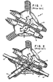
- Figures 1-3 show the prior art means for preventing shielding coaxial connectors, including T-shaped connectors, and especially BNC-type connectors, which include a conductive housing, from being connected to a separate external ground which would disrupt the shielding effect provided thereby.
- This means generally comprises a two-part housing 1 including an upper part 5 and a lower part 3 configured for receiving and holding the connector 11 therein.
- the housing includes a connector support portion 7 which secures the connector within the housing 1.
- the connector is then connected at two female portions or jacks 19 including engaging lugs 21 to male receiving BNC-type connector portions or plugs 15 which are connected respectively for terminating corresponding coaxial cables 13.
- the male portion or plug 17 of the BNC-type T-shaped connector is engaged to a female connector or jack portion which is attached for terminating a like coaxial cable 13.
- the housing is closed upon itself and the top and bottom parts 5 and 3 engaged together by means of latch 9 generally shown in the drawings to be placed in a closed configuration as shown in Figure 3.
- the prior art boot 1 which is typically made of an insulative material is generally cumbersome to use, and it is often the case that the user forgets to place it on the connector 11 once the unit is assembled.
- the connector housing 11 and 15 as shown in Figures 4a and 4b in accordance with the invention is selectively coated at a region 23, in the case of Figure 4a, with an insulative material. More particularly, preferably as shown in Figure 4a, the insulative material region 23 encompasses the male connector portion or plug 17 of the BNC-type connector 11 as well as the middle of the T which leads into the two female portions or jacks 19 which include engaging lugs 21.
- the female connector portions or jacks 19 when assembled to three coaxial cables 13, the female connector portions or jacks 19 will be engaged to the male terminating BNC-type connector plugs 15 for the cables 13 which are shown in Figure 4b, and which as modified for use with the invention are also selectively coated with a non-conductive material on the exposed portions as illustrated.
- the non-exposed portions are connected to the cable 13 braid to maintain shielding and are not coated with the insulative material.
- the entire assembly then has the exposed connector housing parts completely coated with insulative material so that inadvertent separate external grounds disrupting the shielding are avoided.
- the coating can be a number of materials among which are included tetrafluoroethylene polymer commercially available under the trade name Teflon, other plastic materials as well as insulative epoxy materials.
- the coating can be a nylon coating, a rubber coating or the like as will be readily apparent to those of ordinary skill in the art. The same coating techniques and coatings are applied to the termination female connectors 15 of cable assemblies 13 to be connected to the connector 11.
Applications Claiming Priority (2)
| Application Number | Priority Date | Filing Date | Title |
|---|---|---|---|
| US861674 | 1977-12-19 | ||
| US86167486A | 1986-05-09 | 1986-05-09 |
Publications (1)
| Publication Number | Publication Date |
|---|---|
| EP0244657A1 true EP0244657A1 (de) | 1987-11-11 |
Family
ID=25336450
Family Applications (1)
| Application Number | Title | Priority Date | Filing Date |
|---|---|---|---|
| EP87105176A Withdrawn EP0244657A1 (de) | 1986-05-09 | 1987-04-08 | Selektiv abisolierter Koaxialsteckverbinder |
Country Status (2)
| Country | Link |
|---|---|
| EP (1) | EP0244657A1 (de) |
| JP (1) | JPS62268074A (de) |
Cited By (6)
| Publication number | Priority date | Publication date | Assignee | Title |
|---|---|---|---|---|
| US5194012A (en) * | 1991-07-30 | 1993-03-16 | Cairns James L | Spark-proof hostile environment connector |
| US5525073A (en) * | 1994-06-01 | 1996-06-11 | Raychem Corporation | Environmental protection device with manually operated latch mechanism |
| US5796315A (en) * | 1996-07-01 | 1998-08-18 | Tracor Aerospace Electronic Systems, Inc. | Radio frequency connector with integral dielectric coating for direct current blockage |
| EP1378971A1 (de) * | 2002-07-02 | 2004-01-07 | Tyco Electronics AMP GmbH | Koaxial-Steckverbinder mit einem längsgeteilten Abschirmgehäuse, und Koaxial-Winkelsteckverbinder |
| US6893291B2 (en) | 2002-07-02 | 2005-05-17 | Tyco Electronics Amp Gmbh | Coaxial plug connector having a longitudinally divided shield housing, and coaxial angled plug connector |
| CN110517836A (zh) * | 2019-07-13 | 2019-11-29 | 安徽伊法拉电气有限公司 | 一种新型t型绝缘护套 |
Families Citing this family (5)
| Publication number | Priority date | Publication date | Assignee | Title |
|---|---|---|---|---|
| DE3924677A1 (de) * | 1989-07-26 | 1991-02-07 | Daimler Benz Ag | Endverbinder zur kontaktierung von mindestens zwei abgeschirmten kabeln |
| JPH0443874U (de) * | 1990-08-13 | 1992-04-14 | ||
| JPH0617127U (ja) * | 1992-08-05 | 1994-03-04 | 株式会社ニチフ端子工業 | ピン端子用ホルダー |
| JP2626477B2 (ja) * | 1993-07-08 | 1997-07-02 | 日本電気株式会社 | 同軸コネクタ |
| JP6187420B2 (ja) * | 2014-09-11 | 2017-08-30 | 中国電力株式会社 | 変流器 |
Citations (5)
| Publication number | Priority date | Publication date | Assignee | Title |
|---|---|---|---|---|
| US1871397A (en) * | 1929-07-29 | 1932-08-09 | Gen Electric | Electrical connecting apparatus |
| US3324441A (en) * | 1964-12-08 | 1967-06-06 | Springfield Wire | Hermetically sealed electrical connections |
| CH520418A (de) * | 1969-08-05 | 1972-03-15 | Hoesterr Rundfunk | Kupplungsstück für koaxiale Leitungen und Verwendung eines solchen Kupplungsstückes in einer Kupplungsanordnung |
| EP0083464A1 (de) * | 1982-01-06 | 1983-07-13 | Koninklijke Philips Electronics N.V. | Koaxialkabel mit Verbinder |
| US4538869A (en) * | 1984-03-27 | 1985-09-03 | Amp | Electrical connector housing |
-
1987
- 1987-04-08 EP EP87105176A patent/EP0244657A1/de not_active Withdrawn
- 1987-05-07 JP JP62109929A patent/JPS62268074A/ja active Pending
Patent Citations (5)
| Publication number | Priority date | Publication date | Assignee | Title |
|---|---|---|---|---|
| US1871397A (en) * | 1929-07-29 | 1932-08-09 | Gen Electric | Electrical connecting apparatus |
| US3324441A (en) * | 1964-12-08 | 1967-06-06 | Springfield Wire | Hermetically sealed electrical connections |
| CH520418A (de) * | 1969-08-05 | 1972-03-15 | Hoesterr Rundfunk | Kupplungsstück für koaxiale Leitungen und Verwendung eines solchen Kupplungsstückes in einer Kupplungsanordnung |
| EP0083464A1 (de) * | 1982-01-06 | 1983-07-13 | Koninklijke Philips Electronics N.V. | Koaxialkabel mit Verbinder |
| US4538869A (en) * | 1984-03-27 | 1985-09-03 | Amp | Electrical connector housing |
Cited By (7)
| Publication number | Priority date | Publication date | Assignee | Title |
|---|---|---|---|---|
| US5194012A (en) * | 1991-07-30 | 1993-03-16 | Cairns James L | Spark-proof hostile environment connector |
| US5525073A (en) * | 1994-06-01 | 1996-06-11 | Raychem Corporation | Environmental protection device with manually operated latch mechanism |
| US5674089A (en) * | 1994-06-01 | 1997-10-07 | Raychem Corporation | Environmental protection device manually operated latch mechanism |
| US5796315A (en) * | 1996-07-01 | 1998-08-18 | Tracor Aerospace Electronic Systems, Inc. | Radio frequency connector with integral dielectric coating for direct current blockage |
| EP1378971A1 (de) * | 2002-07-02 | 2004-01-07 | Tyco Electronics AMP GmbH | Koaxial-Steckverbinder mit einem längsgeteilten Abschirmgehäuse, und Koaxial-Winkelsteckverbinder |
| US6893291B2 (en) | 2002-07-02 | 2005-05-17 | Tyco Electronics Amp Gmbh | Coaxial plug connector having a longitudinally divided shield housing, and coaxial angled plug connector |
| CN110517836A (zh) * | 2019-07-13 | 2019-11-29 | 安徽伊法拉电气有限公司 | 一种新型t型绝缘护套 |
Also Published As
| Publication number | Publication date |
|---|---|
| JPS62268074A (ja) | 1987-11-20 |
Similar Documents
| Publication | Publication Date | Title |
|---|---|---|
| US4272148A (en) | Shielded connector housing for use with a multiconductor shielded cable | |
| EP0769828B1 (de) | Vollisolierte, vollgeschirmte elektrische Verbindungsanordnung | |
| US5170008A (en) | External cable grommet for cable entry of EMI protected cabinets | |
| US4386819A (en) | RF Shielded assembly having capacitive coupling feature | |
| EP0421373B1 (de) | Modularer Steckverbinder | |
| EP0907221B1 (de) | Elektrischer Kabelsteckverbinder | |
| US4579415A (en) | Grounding of shielded cables in a plug and receptacle electrical connector | |
| US4236779A (en) | EMI Shielded cable and connector assembly | |
| US4846724A (en) | Shielded cable assembly comprising means capable of effectively reducing undesirable radiation of a signal transmitted through the assembly | |
| EP0118168B2 (de) | Elektrischer Steckverbinder und Steckdose dafür | |
| KR970004152B1 (ko) | 전기 접속기용 케이블 차폐 종단 장치 | |
| US4619487A (en) | Flat cable connector with grounding clip | |
| US4674807A (en) | Shielded connector | |
| US20050277335A1 (en) | Shielded jack assemblies and methods for forming a cable termination | |
| CA2041164C (en) | Cable entry device for shielded cabinets | |
| EP0244657A1 (de) | Selektiv abisolierter Koaxialsteckverbinder | |
| JPS62262381A (ja) | 電気コネクタ組立体及びその製造方法 | |
| US4447100A (en) | Apparatus for grounding and terminating a cable | |
| EP0431206B1 (de) | Erdungssteckverbinder und Verfahren | |
| US4498715A (en) | Cable shield grounding clamp | |
| JPH01501825A (ja) | 電気コネクタ | |
| US4399318A (en) | EMI Shielding enclosure for a cable connector | |
| US4674822A (en) | Multi-conductor shielded cable | |
| US11394156B2 (en) | Cable system having shielding layers to reduce and or eliminate EMI leakage | |
| US20030034165A1 (en) | Method and apparatus for external grounding of plastic backshell connectors |
Legal Events
| Date | Code | Title | Description |
|---|---|---|---|
| PUAI | Public reference made under article 153(3) epc to a published international application that has entered the european phase |
Free format text: ORIGINAL CODE: 0009012 |
|
| AK | Designated contracting states |
Kind code of ref document: A1 Designated state(s): DE FR GB IT |
|
| STAA | Information on the status of an ep patent application or granted ep patent |
Free format text: STATUS: THE APPLICATION IS DEEMED TO BE WITHDRAWN |
|
| 18D | Application deemed to be withdrawn |
Effective date: 19880512 |
|
| RIN1 | Information on inventor provided before grant (corrected) |
Inventor name: SAVERIO, THOMAS BRUNO |