EP0244633A2 - Ignition device for combustion engines - Google Patents
Ignition device for combustion engines Download PDFInfo
- Publication number
- EP0244633A2 EP0244633A2 EP87104801A EP87104801A EP0244633A2 EP 0244633 A2 EP0244633 A2 EP 0244633A2 EP 87104801 A EP87104801 A EP 87104801A EP 87104801 A EP87104801 A EP 87104801A EP 0244633 A2 EP0244633 A2 EP 0244633A2
- Authority
- EP
- European Patent Office
- Prior art keywords
- primary winding
- control current
- switching transistor
- ignition system
- switching
- Prior art date
- Legal status (The legal status is an assumption and is not a legal conclusion. Google has not performed a legal analysis and makes no representation as to the accuracy of the status listed.)
- Granted
Links
Images
Classifications
-
- F—MECHANICAL ENGINEERING; LIGHTING; HEATING; WEAPONS; BLASTING
- F02—COMBUSTION ENGINES; HOT-GAS OR COMBUSTION-PRODUCT ENGINE PLANTS
- F02P—IGNITION, OTHER THAN COMPRESSION IGNITION, FOR INTERNAL-COMBUSTION ENGINES; TESTING OF IGNITION TIMING IN COMPRESSION-IGNITION ENGINES
- F02P3/00—Other installations
- F02P3/02—Other installations having inductive energy storage, e.g. arrangements of induction coils
- F02P3/04—Layout of circuits
- F02P3/045—Layout of circuits for control of the dwell or anti dwell time
- F02P3/0453—Opening or closing the primary coil circuit with semiconductor devices
Definitions
- the invention relates to an ignition system according to the preamble of the main claim.
- the invention has for its object to provide an ignition system according to the preamble of the main claim and to avoid the aforementioned inadequacy.
- the circuit part shown should belong to the ignition system of an internal combustion engine intended for a motor vehicle.
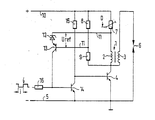
- the circuit part has an ignition coil 1 with a primary winding 2 and a secondary winding 3.
- the primary winding 2 is connected to the collector of a switching transistor 4, the emitter of which is connected to the ground line 5 connected to the negative pole of a current source (not shown).
- the secondary winding 3 has at its one connection to the connection of the primary winding 3 facing the switching transistor 4 and at its other connection directly to the one connection of a spark plug 6.
- the other connection of the spark plug 6 is connected to the ground line 5.
- the primary winding 2 forms a bridge circuit in conjunction with three ohmic resistors 7, 8, 9.
- the primary winding 2 is connected with its connection facing away from the switching transistor 4 via the bridge resistor 7 to a supply line 10 starting from the positive pole of the current source.
- the bridge resistors 8, 9 form a series circuit which has one end at the connection between the primary winding 2 and the switching transistor 4 and the other end at the supply line 10.
- One end of a diagonal branch 11 is connected to the one between the primary winding 2 and the bridge resistor 7 Connection and connected at its other end to the connection existing between bridge resistor 8 and bridge resistor 9.
- Uref reference voltage
- a zener diode 12 and the series-emitter-base path of a (pnp) control transistor 13 are used for this, the cathode of the zener diode 12 of the connection between primary winding 2 and bridge resistor 7 and the base of the control transistor 13 of the connection is facing between bridge resistor 8 and bridge resistor 9.
- the collector of the control transistor 13 is connected to the base of an (npn) driver transistor 14, the emitter of which is connected to the ground line 5 and the collector of which is connected both to the base of the switching transistor 4 and via a resistor 15 to the supply line 10.
- the driver transistor 14 can be controlled by a decoupling resistor 16 on its emitter-collector path in the blocking state and, depending on this, the switching transistor 4 on its emitter-collector path in its current transmission state can be controlled by a pulse i supplied by a signal generator (not shown).
- the bridge circuit can be adjusted as a function of an operating parameter of the internal combustion engine.
- the bridge resistance 7 is designed to be adjustable in the example, the resistance value of the bridge resistance 7 being intended to decrease as the compression D in the cylinder increases.
- the circuit section just described has the following mode of operation: As soon as the pulse i turns the driver transistor 14 off and the switching transistor 4 on, the current in the primary winding 2 begins to rise.
- This increase should be at least almost optimal, that is, on the one hand, it should be "fast” enough so that even at high speeds between two ignition points there is sufficient time for storing an effective ignition energy amount and at the same time there is time for the formation of powerful ignition sparks, and on the other hand the increase is not so "fast” that the voltage thereby generated in the secondary winding 3 on the spark plug 6 causes an undesirable ignition spark.
- control transistor 13 on its emitter-collector path and, depending on it, the driver transistor 14 on its emitter-collector path is turned on by the reference voltage Uref to such an extent that it causes it at the base of the switching transistor 4 and via the emitter Collector path of the driver transistor 14 running control current branch ensures an optimal charging time constant. Good results can be achieved if the voltage drop dependent on the ohmic resistance of the primary winding 2 is at least almost compensated for with the aid of this control current branch.
- the bridge circuit can be set as a function of at least one operating parameter of the internal combustion engine.
- the resistance value of the bridge resistor 7 is reduced with increasing compression in the cylinder, because then the secondary voltage required for an ignition spark is also at higher values and consequently the advantage of the "rapid" current increase in the primary winding 2 can be used.
- the bridge resistance 7, which is in series with the primary winding 2 can be selected to be higher than is necessary to compensate for the ohmic voltage drop of the primary winding 2.
- the voltage across the secondary winding 3 thus increases with increasing current, which is possible because of the higher sparkover breakdown voltage permitted by the increasing compression
Landscapes
- Engineering & Computer Science (AREA)
- Chemical & Material Sciences (AREA)
- Combustion & Propulsion (AREA)
- Mechanical Engineering (AREA)
- General Engineering & Computer Science (AREA)
- Ignition Installations For Internal Combustion Engines (AREA)
Abstract
Es wird eine Zündanlage für Brennkraftmaschinen vorgeschlagen, die eine wenigstens an eine Zündkerze (6) unmittelbar angeschlossene Sekundärwicklung (3) und eine in Serie zur Schaltstrecke eines Schalttransistors (4) liegende Primärwicklung (2) hat. Erfindungsgemäß ist hier die Primärwicklung (2) Bestandteil einer Brückenschaltung, wobei eine in deren Diagonalzweig (11) erzeugte Referenzspannu ng (Uref) für die Steuerung eines zur Steuerstromabzweigung am Schalttransistor (4) benutzten Schaltgliedes (14) Verwendung findet und wobei ferner mit Hilfe dieser Steuerstromabzweigung eine optimale Ladezeitkonstante in dem Stromkreis der Primärwicklugn (2) festgelegt ist. 
Description
Die Erfindung bezieht sich auf eine Zündanlage nach dem Oberbegriff des Hauptanspruches.The invention relates to an ignition system according to the preamble of the main claim.
In Zündanlagen, in denen die Sekundärwicklungen der Zündspulen mit einer bzw. mehreren Zündkerzen unmittelbare Verbindung haben, wie das beispielsweise bei einkerzigen bzw. verteilerlosen mehrkerzigen zündanlagen der Fall ist, besteht die Gefahr, daß beim Einschalten des für die Zündspule bestimmten Primärstromes in der Sekundärwicklung eine so hohe Spannung induziert wird, daß an der Zündkerze ein Zündfunke auftritt und zwar in einem Zeitpunkt, in dem die Brennkraftmaschine Schaden erleiden kann.In ignition systems in which the secondary windings of the ignition coils have a direct connection to one or more spark plugs, as is the case, for example, in the case of single-plug or distributorless multi-plug ignition systems, there is a risk that when the primary current intended for the ignition coil is switched on in the secondary winding such a high voltage is induced that an ignition spark occurs at the spark plug at a time when the internal combustion engine can be damaged.
Der Erfindung liegt die Aufgabe zugrunde, eine Zündanlage nach dem Oberbegriff des Hauptanspruches zu schaffen und dabei die vorerwähnte Unzulänglichkeit zu vermeiden.The invention has for its object to provide an ignition system according to the preamble of the main claim and to avoid the aforementioned inadequacy.
Diese Aufgabe wird durch Anwendung der im kennzeichnenden Teil des Hauptanspruches aufgeführten Maßnahmen gelöst.This object is achieved by applying the measures listed in the characterizing part of the main claim.
In den Unteransprüchen sind vorteilhafte Maßnahmen für die Realisierung der Erfindung angegeben.Advantageous measures for realizing the invention are specified in the subclaims.
Ein Ausführungsbeispiel der Erfindung ist in der Zeichnung schaltungsmäßig dargestellt und in der nachfolgenden Beschreibung näher erläutert.An embodiment of the invention is shown in the drawing in terms of circuitry and explained in more detail in the following description.
Der dargestellte Schaltungsteil soll zu der Zündanlage einer für ein Kraftfahrzeug bestimmten Brennkraftmaschine gehören. Der Schaltungsteil hat eine Zündspule 1 mit einer Primärwicklung 2 und einer Sekundärwicklung 3. Die Primärwicklung 2 ist an den Kollektor eines Schalttransistors 4 angeschlossen, dessen Emitter an der mit dem Minuspol einer nicht dargestellten Stromquelle verbundenen Masseleitung 5 liegt. Die Sekundärwicklung 3 hat an ihrem einen Anschluß mit dem dem Schalttransistor 4 zugewandten Anschluß der Primärwicklung 3 und an ihrem anderen Anschluß unmittelbar mit dem einen Anschluß einer Zündkerze 6 Verbindung. Der andere Anschluß der Zündkerze 6 liegt an der Masseleitung 5.The circuit part shown should belong to the ignition system of an internal combustion engine intended for a motor vehicle. The circuit part has an ignition coil 1 with a primary winding 2 and a secondary winding 3. The primary winding 2 is connected to the collector of a switching transistor 4, the emitter of which is connected to the
Schließlich bildet die Primärwicklung 2 in Verbindung mit drei ohmschen Widerständen 7, 8, 9 eine Brückenschaltung. Dabei ist die Primärwicklung 2 mit ihrem dem Schalttransistor 4 abgewandten Anschluß über den Brückenwiderstand 7 an eine von dem Pluspol der Stromquelle ausgehende Versorgungsleitung 10 angeschlossen. Die Brückenwiderstände 8, 9 bilden eine Serienschaltung, die mit ihrem einen Ende an der zwischen Primärwicklung 2 und Schalttransistor 4 vorhanden Verbindung und mit ihrem anderen Ende an der Versorgungsleitung 10 liegt. Ein Diagonalzweig 11 ist mit seinem einen Ende an die zwischen Primärwicklung 2 und Brückenwiderstand 7 vorhandene Verbindung und mit seinem anderen Ende an die zwischen Brückenwiderstand 8 und Brückenwiderstand 9 vorhandene Verbindung angeschlossen. Im Diagonalzweig 11 liegt eine Referenzspannung Uref, wofür im bevorzugten Fall Schaltungselemente mit bestimmter Durchbruchsspannung vorgesehen sind. Im vorliegenden Fall sind hierfür eine Zenerdiode 12 und die in Serie dazu liegende Emitter-Basis-Strecke eines (pnp-) Steuertransistors 13 benutzt, wobei die Kathode der Zenerdiode 12 der Verbindung zwischen Primärwicklung 2 und Brückenwiderstand 7 und die Basis des Steuertransistors 13 der Verbindung zwischen Brückenwiderstand 8 und Brückenwiderstand 9 zugewandt ist. Der Kollektor des Steuertransistors 13 ist mit der Basis eines (npn-) Treibertransistors 14 verbunden, dessen Emitter an der Masseleitung 5 und dessen Kollektor sowohl an der Basis des Schalttransistors 4 als auch über einen Widerstand 15 an der Versorgungsleitung 10 liegt.Finally, the primary winding 2 forms a bridge circuit in conjunction with three
Durch einen von einem nicht dargestellten Signalgeber gelieferten Impuls i ist der Treibertransistor 14 über einen Entkopplungswiderstand 16 an seiner Emitter-Kollektor-Strecke in den Sperrzustand und abhängig davon der Schalttransistor 4 an seiner Emitter-Kollektor-Strecke in seinen Stromdurchlaßzustand steuerbar.The
Vorteilhaft ist es, wenn sich die Brückenschaltung in Abhängigkeit von we ngistens einem Betriebsparameter der Brennkraftmaschine verstellen läßt. Zu diesem Zweck ist im Beispielsfall der Brückenwiderstand 7 verstellbar ausgeführt, wobei der Widerstandswert des Brückenwiderstandes 7 mit steigender Verdichtung D im Zylinder kleiner werden soll.It is advantageous if the bridge circuit can be adjusted as a function of an operating parameter of the internal combustion engine. For this purpose, the bridge resistance 7 is designed to be adjustable in the example, the resistance value of the bridge resistance 7 being intended to decrease as the compression D in the cylinder increases.
Der soeben beschriebene Schaltungsteil hat folgende Wirkungsweise:
Sobald der Impuls i den Treibertransistor 14 aus- und den Schalttransistor 4 einschaltet, beginnt der Strom in der Primärwicklung 2 anzusteigen. Dieser Anstieg soll wenigstens nahezu optimal sein, d.h. er soll einerseits "schnell" genug sein, damit auch bei hohen Drehzahlen zwischen zwei Zündpunkten ausreichende Zeit für die Speicherung eines wirkungsvollen Zündenergiebetrages un gleichzeitig auch Zeit für die Ausbildung kräftigen Zündfunkens bleibt, und daß andererseits der Anstieg nicht so "schnell" ist, daß die dabei in der Sekundärwicklung 3 entstehende Spannung an der Zündkerze 6 einen unerwünschten Zündfunken hervorruft. Zu diesem Zweck wird der Steuertransistor 13 an seiner Emitter-Kollektor-Strecke und abhängig davon der Treibertransistor 14 an seiner Emitter-Kollektor-Strecke durch die Referenzspannung Uref so weit aufgesteuert, daß die dadurch an der Basis des Schalttransistors 4 verursachte und über die Emitter-Kollektor-Strecke des Treibertransistors 14 verlaufende Steuerstromabzweigung für eine optimale Ladezeitkonstante sorgt. Dabei erreicht man gute Ergebnisse, wenn mit Hilfe dieser Steuerstromabzweigung der vom ohmschen Widerstand der Primärwicklung 2 abhängige Spannungsabfall wenigstens nahezu kompensiert wird.The circuit section just described has the following mode of operation:
As soon as the pulse i turns the
Vorteilhaft ist es, wenn sich die Brückenschaltung in Abhängigkeit von wenigstens einem Betriebsparameter der Brennkraftmaschine einstellen läßt. Im Beispielsfall wird der Widerstandswert des Brückenwiderstandes 7 mit zunehmender Verdichtung im Zylinder verkleinert, weil dann die für einen Zündfunken notwendige Sekundärspannung ebenfalls bei höheren Werten liegt und demzufolge vom Vorteil des "schnellen" Stromanstieges in der Primärwicklung 2 Gebrauch gemacht werden kann.It is advantageous if the bridge circuit can be set as a function of at least one operating parameter of the internal combustion engine. In the example, the resistance value of the bridge resistor 7 is reduced with increasing compression in the cylinder, because then the secondary voltage required for an ignition spark is also at higher values and consequently the advantage of the "rapid" current increase in the primary winding 2 can be used.
In einer weiteren Variante kann der mit der Primärwicklung 2 in Serie liegende Brückenwiderstand 7 höher gewählt werden als das zur Kompensation des ohmschen Spannungsabfalls der Primärwicklung 2 notwendig ist. Damit nimmt die Spannung über der Sekundärwicklung 3 mit steigendem Strom zu, was wegen der durch die steigende Verdichtung zulässigen höheren Kerzen-Überschlagspannung möglich ist In a further variant, the bridge resistance 7, which is in series with the primary winding 2, can be selected to be higher than is necessary to compensate for the ohmic voltage drop of the primary winding 2. The voltage across the secondary winding 3 thus increases with increasing current, which is possible because of the higher sparkover breakdown voltage permitted by the increasing compression
Claims (3)
Applications Claiming Priority (2)
| Application Number | Priority Date | Filing Date | Title |
|---|---|---|---|
| DE19863615548 DE3615548A1 (en) | 1986-05-09 | 1986-05-09 | IGNITION SYSTEM FOR INTERNAL COMBUSTION ENGINES |
| DE3615548 | 1986-05-09 |
Publications (3)
| Publication Number | Publication Date |
|---|---|
| EP0244633A2 true EP0244633A2 (en) | 1987-11-11 |
| EP0244633A3 EP0244633A3 (en) | 1988-04-06 |
| EP0244633B1 EP0244633B1 (en) | 1991-09-18 |
Family
ID=6300396
Family Applications (1)
| Application Number | Title | Priority Date | Filing Date |
|---|---|---|---|
| EP19870104801 Expired - Lifetime EP0244633B1 (en) | 1986-05-09 | 1987-04-01 | Ignition device for combustion engines |
Country Status (3)
| Country | Link |
|---|---|
| US (1) | US4886037A (en) |
| EP (1) | EP0244633B1 (en) |
| DE (2) | DE3615548A1 (en) |
Cited By (1)
| Publication number | Priority date | Publication date | Assignee | Title |
|---|---|---|---|---|
| WO1991015058A1 (en) * | 1990-03-23 | 1991-10-03 | Robert Bosch Gmbh | Short-circuit resistant transistor final stage, in particular ignition final stage for motor vehicles |
Families Citing this family (9)
| Publication number | Priority date | Publication date | Assignee | Title |
|---|---|---|---|---|
| JPH08270534A (en) * | 1995-03-31 | 1996-10-15 | Mitsubishi Electric Corp | Ignition device for internal combustion engine |
| JP3216966B2 (en) * | 1995-04-04 | 2001-10-09 | 三菱電機株式会社 | Ignition device for internal combustion engine |
| DE19605803A1 (en) * | 1996-02-16 | 1997-08-21 | Daug Deutsche Automobilgesells | Circuit arrangement for ion current measurement |
| DE19711204C2 (en) * | 1997-03-18 | 1999-01-14 | Bosch Gmbh Robert | Circuit arrangement of an ignition output stage |
| DE19741439A1 (en) * | 1997-09-19 | 1999-03-25 | Bayerische Motoren Werke Ag | IC engine ignition preparation, ignition coil primary current switching on device |
| US6131555A (en) * | 1998-04-20 | 2000-10-17 | Cummins Engine Company, Inc. | System for controlling ignition energy of an internal combustion engine |
| US6035838A (en) * | 1998-04-20 | 2000-03-14 | Cummins Engine Company, Inc. | Controlled energy ignition system for an internal combustion engine |
| JP2000205034A (en) * | 1999-01-18 | 2000-07-25 | Mitsubishi Electric Corp | Device for detecting combustion state of internal combustion engine |
| US6247465B1 (en) * | 2000-02-11 | 2001-06-19 | Delphi Technologies, Inc. | System and method for preventing spark-on-make in an internal combustion engine using manifold pressure |
Family Cites Families (12)
| Publication number | Priority date | Publication date | Assignee | Title |
|---|---|---|---|---|
| US432493A (en) * | 1890-07-15 | Martin s | ||
| US2487186A (en) * | 1946-01-23 | 1949-11-08 | Teletype Corp | Plural transmitter telegraph system with number transmitter |
| US3145727A (en) * | 1962-08-17 | 1964-08-25 | Ajinomoto Kk | Automatic liquid level control device |
| US3206032A (en) * | 1963-06-24 | 1965-09-14 | M C Nottingham Co Of Temple Ci | Sewage disposal tank |
| US3805957A (en) * | 1972-03-31 | 1974-04-23 | Oldham R Inc | Floating solids return device |
| FR2217566A1 (en) * | 1973-02-10 | 1974-09-06 | Lucas Electrical Co Ltd | |
| US3931817A (en) * | 1975-01-27 | 1976-01-13 | Leonard Infranca | Pediatric corrective device |
| DE2542677C3 (en) * | 1975-09-25 | 1978-11-23 | Robert Bosch Gmbh, 7000 Stuttgart | Ignition device for an internal combustion engine |
| JPS6053795B2 (en) * | 1978-03-14 | 1985-11-27 | 株式会社デンソー | internal combustion engine ignition system |
| US4326493A (en) * | 1979-07-26 | 1982-04-27 | Autotronic Controls, Corp. | Multiple spark discharge ignition system |
| DE3007335A1 (en) * | 1980-02-27 | 1981-09-10 | Robert Bosch Gmbh, 7000 Stuttgart | IGNITION SYSTEM FOR AN INTERNAL COMBUSTION ENGINE |
| JPH0694864B2 (en) * | 1984-07-26 | 1994-11-24 | 日本電装株式会社 | Ignition device for internal combustion engine |
-
1986
- 1986-05-09 DE DE19863615548 patent/DE3615548A1/en not_active Withdrawn
-
1987
- 1987-03-17 US US07/026,864 patent/US4886037A/en not_active Expired - Fee Related
- 1987-04-01 DE DE8787104801T patent/DE3773043D1/en not_active Expired - Lifetime
- 1987-04-01 EP EP19870104801 patent/EP0244633B1/en not_active Expired - Lifetime
Cited By (1)
| Publication number | Priority date | Publication date | Assignee | Title |
|---|---|---|---|---|
| WO1991015058A1 (en) * | 1990-03-23 | 1991-10-03 | Robert Bosch Gmbh | Short-circuit resistant transistor final stage, in particular ignition final stage for motor vehicles |
Also Published As
| Publication number | Publication date |
|---|---|
| DE3615548A1 (en) | 1987-11-12 |
| EP0244633A3 (en) | 1988-04-06 |
| EP0244633B1 (en) | 1991-09-18 |
| DE3773043D1 (en) | 1991-10-24 |
| US4886037A (en) | 1989-12-12 |
Similar Documents
| Publication | Publication Date | Title |
|---|---|---|
| DE2340865C3 (en) | Ignition device for an internal combustion engine | |
| EP0640761B2 (en) | Controllable ignition system | |
| DE2636945A1 (en) | IGNITION SYSTEM FOR COMBUSTION MACHINES WITH A MAGNETIC GENERATOR | |
| DE2734164A1 (en) | ELECTRONIC IGNITION CONTROL SYSTEM FOR COMBUSTION ENGINE, IN PARTICULAR FOR MOTOR VEHICLES | |
| EP0034787A1 (en) | Ignition system for internal-combustion engines | |
| EP0244633B1 (en) | Ignition device for combustion engines | |
| DE2927058C2 (en) | Control device for an ignition coil | |
| DE69019323T2 (en) | Speed limiter for internal combustion engines. | |
| EP0489264B1 (en) | Electronic ignition system | |
| DE2433155B2 (en) | Ignition circuit for a multi-cylinder internal combustion engine | |
| EP0850358B1 (en) | Final ignition stage | |
| DE19755140B4 (en) | Ignition system with ignition coil | |
| DE3404245C2 (en) | High-voltage generator circuit for a motor vehicle ignition system | |
| DE2920831C2 (en) | Ignition system for internal combustion engines with a magnet generator | |
| DE69813953T2 (en) | Ignition device for internal combustion engines | |
| DE19741963C1 (en) | Device for suppressing undesired ignition in petrol engine | |
| DE2527725B2 (en) | Circuit arrangement for internal combustion engine ignition devices | |
| DE102004015543B4 (en) | Ignition system for an internal combustion engine | |
| DE3152015C2 (en) | Electronic ignition device for internal combustion engines | |
| DE3215728A1 (en) | IGNITION SYSTEM FOR AN INTERNAL COMBUSTION ENGINE | |
| DE2825830A1 (en) | Ignition system for IC engine - has cold start facility and controls switching as function of temp. and speed to raise current level in primary winding | |
| DE3423949A1 (en) | IGNITION SYSTEM FOR INTERNAL COMBUSTION ENGINES | |
| DE4133253A1 (en) | IC engine ignition system with overvoltage protection - has blocking diode connected in series with resistor and in parallel with spark plug, to limit current flow | |
| EP0230405B1 (en) | Ignition device with magnetic generator for internal combustion engine | |
| DE10260321B4 (en) | Circuit arrangement for radio interference suppression of a motor vehicle ignition system |
Legal Events
| Date | Code | Title | Description |
|---|---|---|---|
| PUAI | Public reference made under article 153(3) epc to a published international application that has entered the european phase |
Free format text: ORIGINAL CODE: 0009012 |
|
| AK | Designated contracting states |
Kind code of ref document: A2 Designated state(s): DE FR IT SE |
|
| PUAL | Search report despatched |
Free format text: ORIGINAL CODE: 0009013 |
|
| AK | Designated contracting states |
Kind code of ref document: A3 Designated state(s): DE FR IT SE |
|
| 17P | Request for examination filed |
Effective date: 19880831 |
|
| 17Q | First examination report despatched |
Effective date: 19910228 |
|
| GRAA | (expected) grant |
Free format text: ORIGINAL CODE: 0009210 |
|
| AK | Designated contracting states |
Kind code of ref document: B1 Designated state(s): DE FR IT SE |
|
| ET | Fr: translation filed | ||
| REF | Corresponds to: |
Ref document number: 3773043 Country of ref document: DE Date of ref document: 19911024 |
|
| ITF | It: translation for a ep patent filed | ||
| RAP4 | Party data changed (patent owner data changed or rights of a patent transferred) |
Owner name: ROBERT BOSCH GMBH |
|
| PLBE | No opposition filed within time limit |
Free format text: ORIGINAL CODE: 0009261 |
|
| STAA | Information on the status of an ep patent application or granted ep patent |
Free format text: STATUS: NO OPPOSITION FILED WITHIN TIME LIMIT |
|
| 26N | No opposition filed | ||
| PGFP | Annual fee paid to national office [announced via postgrant information from national office to epo] |
Ref country code: SE Payment date: 19940421 Year of fee payment: 8 |
|
| PGFP | Annual fee paid to national office [announced via postgrant information from national office to epo] |
Ref country code: FR Payment date: 19940429 Year of fee payment: 8 |
|
| PGFP | Annual fee paid to national office [announced via postgrant information from national office to epo] |
Ref country code: DE Payment date: 19940628 Year of fee payment: 8 |
|
| EAL | Se: european patent in force in sweden |
Ref document number: 87104801.3 |
|
| PG25 | Lapsed in a contracting state [announced via postgrant information from national office to epo] |
Ref country code: SE Effective date: 19950402 |
|
| PG25 | Lapsed in a contracting state [announced via postgrant information from national office to epo] |
Ref country code: FR Effective date: 19951229 |
|
| PG25 | Lapsed in a contracting state [announced via postgrant information from national office to epo] |
Ref country code: DE Effective date: 19960103 |
|
| EUG | Se: european patent has lapsed |
Ref document number: 87104801.3 |
|
| REG | Reference to a national code |
Ref country code: FR Ref legal event code: ST |
|
| PG25 | Lapsed in a contracting state [announced via postgrant information from national office to epo] |
Ref country code: IT Free format text: LAPSE BECAUSE OF NON-PAYMENT OF DUE FEES;WARNING: LAPSES OF ITALIAN PATENTS WITH EFFECTIVE DATE BEFORE 2007 MAY HAVE OCCURRED AT ANY TIME BEFORE 2007. THE CORRECT EFFECTIVE DATE MAY BE DIFFERENT FROM THE ONE RECORDED. Effective date: 20050401 |