EP0244574A1 - Device for the treatment of a body having a cylindrical surface by using a laser - Google Patents
Device for the treatment of a body having a cylindrical surface by using a laser Download PDFInfo
- Publication number
- EP0244574A1 EP0244574A1 EP87102289A EP87102289A EP0244574A1 EP 0244574 A1 EP0244574 A1 EP 0244574A1 EP 87102289 A EP87102289 A EP 87102289A EP 87102289 A EP87102289 A EP 87102289A EP 0244574 A1 EP0244574 A1 EP 0244574A1
- Authority
- EP
- European Patent Office
- Prior art keywords
- bearing
- shaft
- carrier shaft
- laser
- axis
- Prior art date
- Legal status (The legal status is an assumption and is not a legal conclusion. Google has not performed a legal analysis and makes no representation as to the accuracy of the status listed.)
- Granted
Links
Images

Classifications
-
- B—PERFORMING OPERATIONS; TRANSPORTING
- B23—MACHINE TOOLS; METAL-WORKING NOT OTHERWISE PROVIDED FOR
- B23K—SOLDERING OR UNSOLDERING; WELDING; CLADDING OR PLATING BY SOLDERING OR WELDING; CUTTING BY APPLYING HEAT LOCALLY, e.g. FLAME CUTTING; WORKING BY LASER BEAM
- B23K26/00—Working by laser beam, e.g. welding, cutting or boring
- B23K26/08—Devices involving relative movement between laser beam and workpiece
- B23K26/0823—Devices involving rotation of the workpiece
Definitions
- the invention relates to a device for machining a body with a circular cylindrical surface by means of a laser, with bearing means by means of which the body is rotatably mounted in a stand about an axis of rotation coaxial with its circular cylindrical surface, with a straight guide for the laser parallel to the axis of rotation , with a linear drive for the laser and a rotary drive for the body and with a control for the synchronized drive of the laser with the body.
- a device of this type is known from EP-PS 72 609.
- the laser is used to produce depressions in the cylindrical surface of a gravure cylinder.
- the cylinder is rotated at a constant speed and the laser is moved in parallel to the cylinder axis.
- the output of the laser is controlled depending on the movement of the laser and the rotation of the cylinder according to a specific pattern by the controller.
- the invention is based on the object of designing a device of the type mentioned at the outset in such a way that it can be used to produce a roller with inserted knives, by means of which blanks are then cut from a sheet-like material, e.g. from cardboard sheets, for the production of folding boxes, similar to what can be cut with rotary printing.
- the bearing means are designed to hold at least one circular-cylindrical, bowl-shaped body, that an incremental length measuring device for the movement of the laser, an incremental angle measuring device for the rotary movement of the carrier shaft and there is a computer which controls the linear drive and the rotary drive as a function of measured values of the length and angle measuring devices.
- the bearing means are designed to hold at least one circular-cylindrical, bowl-shaped body
- at least one bowl-shaped body can be used for processing by the laser through which incisions which are then continuous for the insertion of knives can be made by means of the laser, for example by burning out.
- a cutting roller can then be put together on a carrier, which can then be used to cut the film-shaped material according to the above-mentioned object.
- linear drive of the laser and the rotary drive of the body are controlled as a function of measured values of the incremental length and angle measuring devices ensures that, with a suitable program of the computer, the laser with one for perfect manufacture for any cutting direction on the curved shell , e.g. burning out, a continuous incision required optimal constant relative speed is movable relative to the shell. ,.
- the invention also enables a particularly advantageous embodiment of the device according to the invention in that the distance of the axis of rotation from the guide of the laser can be adjusted in one setting direction.
- any line-shaped incisions can be made in shell-shaped bodies which are bent to any desired radius with a constant relative speed.
- the rotary bearing has two bearing blocks for the rotatable mounting of one bearing shaft each and that the one bearing shaft is connected to a drive. This creates the possibility that a carrier shaft can be used for the rotating body, the ends of which can be connected coaxially to the mutually facing ends of the bearing shafts.
- a particularly simple connection of the ends of the carrier shaft to the bearing shafts results from the fact that to form bearing surfaces for the ends of the carrier shaft in the ends of the bearing shafts along a surface parallel to the shaft axis, preferably along a diametrical plane, and along an angle forming an angle therewith Surface, preferably along a radial plane, cylinder segments are cut out, so that the remaining cylinder segment forms the bearing surface.
- the carrier shaft has two bearing wheels for mounting shell-shaped bodies.
- the bowl-shaped bodies to be machined can be attached to the rims of the bearing wheels, e.g. to be screwed onto this.
- the bowl-shaped bodies enclose an intermediate space between them and the carrier shaft. This gap can be used in further advantageous embodiments to ensure that when the incisions are burned out in e.g. Plywood resulting smoke gases can be extracted through this space.
- this is achieved in that the carrier shaft is hollow at least at its output end and the bearing shaft and in that the cavity of the carrier shaft is connected to the outside space, that is to say the said space, by radial openings. If you then connect a suction hose to the free end of the bearing shaft at the output end of the carrier shaft, the flue gases generated during the cutting are immediately sucked into the space and through it through the cavities of the carrier shaft and the bearing shaft.
- the device shown in FIGS. 1 to 5 is used to produce continuous incisions in two circular cylindrical half-shells 11 and 12 by means of a laser 13, which is guided along a guide 14 parallel to the axis 15 of the half-shells 11 and 12 vertically above this and via a in the drawing, not shown spindle is movable by a motor 16.
- the guide 14 and the motor 16 are carried by a stand 17 arranged behind the device.
- the half-shells 11 and 12 are made of plywood. Through the beam of the laser 13, the continuous incisions are burned into the half-shells, which are used to hold knives. These half-shells 11 and 12 are then attached to a roller. This roller then interacts with a counter roller, so that cardboard blanks are cut out of cardboard sheets which are passed through the roll gap.
- the burnt-out incisions can also be used so that, in addition to the knives, tools for embossing grooves are also used, so that the cut or punched-out cardboard blanks are simultaneously provided with folding grooves in the rotation process.
- a hollow carrier shaft 18 is mounted under the guide 14 of the laser 13 between two bearing blocks designated 19 and 21 as a whole in FIG.
- two bearing wheels 22 and 23 are fastened in the vicinity of the two ends of the carrier shaft 18, one of which bearing wheel 23 is axially displaceable and clampable on the carrier shaft 18 by means of a clamping device 24, which can be actuated by handles 25, of which only one is shown in the drawing.
- This is a known clamping device using a screw-in truncated cone, which is therefore neither shown nor described in detail.
- Each bearing wheel 22 and 23 is provided with a rim-like widening 26 which is provided with radial hollow threads which serve to receive fastening screws by means of which the shells 11 and 12 can be fastened to the wheels 22 and 23.
- spokes 27 are also provided between the wheels 22 and 23, which also serve to connect the shells 11 and 142 to the carrier shaft 18 by screws.
- cover disks 29 and 31 are provided outside the bearing wheels 22 and 23 provided with holes to reduce the inertial mass.
- the carrier shaft 18 has radial bores 32 which connect the intermediate space 28 to the cavity 33 of the carrier shaft.
- the connected to the adjacent cover plate 31 and axially displaceable bearing wheel 23 is connected to the adjacent end of the carrier shaft 18 with a bellows 30 comprising the carrier shaft 18, which serves to prevent the radial bores 32 opening into the intermediate space 28 when the bearing wheel is displaced connect to.
- Each of the two bearing blocks 19 and 21 can be moved up and down by means of a hydraulic cylinder 34 and 35 and for this purpose has a frame 37 and 3A guided in four vertical columns 36.
- a detent column 39 and 41 Coaxial with the cylinders 34 and 35 is a detent column 39 and 41, respectively, which is provided on its outer circumference with detent recesses 42 into which a bolt 43 engages in its locking position, from which it is lifted when the pedestal 19 and 21 respectively inclined boundary surfaces of the locking recess are pressed out against the force of a spring 44 into an unlocking position and held in this by an electromagnet 45.
- the locking device formed by the locking bolt 43, the spring 44 and the electromagnet 45 is arranged in a ring 46 fastened to the frame 37 or 38 and comprising the remaining column 39 or 41.
- the frames 37 and 38 of the bearing blocks 19 and 21 carry rotary bearings for the carrier shaft 18.
- the rotary bearing of the bearing block 19 has a bearing shaft 47 which is rotatably mounted in bearings 48 and is not axially displaceable.
- the bearings 48 are arranged on a platform 49 which is connected to the frame 37 by means of a linkage 51 and to the piston rod 53 of the hydraulic cylinder 34 by means of an adjusting device 52.
- the adjusting device 52 serves to be able to precisely adjust the position of the platform relative to the piston rod 53.
- An incremental angle measuring device 54 is attached to the platform 49, which measures the angle of rotation of the bearing shaft 47, the output of which is connected to a computer 55, which is also connected to the output of an incremental length measuring device 20 which gives the computer the position of the laser 13.
- a gear 56 is fastened, which is used for driving by a toothed belt 57 which is omitted in FIG. 1 and which can be driven by the pinion 58 of a motor 59.
- a tensioning roller 61 is provided for tensioning the toothed belt 57.
- the motor 59 is connected to the computer 55 for receiving control signals, as is the drive motor of the laser 13.
- the piston rod 64 of the cylinder 35 is connected via an actuating device 62 to a bearing 68 which is connected to the frame 38 by a frame 60 and in which a hollow bearing shaft 67 is rotatably and axially immovable.
- the bearing shaft 67 has the same diameter as the carrier shaft 18.
- suction hose 65 which is only schematically indicated in the drawing, to a suction device 66, by means of which suction device 66 is used to cut continuous incisions into the half-shells from the space 28 11 and 12 resulting smoke gases through the radial bores 32, the cavities 33 and 63 of the carrier shaft 18 or bearing shaft 67 can be extracted.
- a blind bore 70 which is coaxial with the bearing shaft axis is drilled in the end of the bearing shaft 47.
- a cylinder segment 71 is then cut out from this end of the bearing shaft 47 along a diametral plane 72 and a radial plane aligned with the bottom of the blind bore 70.
- the carrier shaft 18 is connected for connection to the bearing shaft 47 with a connector 74 made of solid material, which closes the cavity of the carrier shaft 18 at this end.
- This connecting piece 74 has a stub shaft 75 which is coaxial with the carrier shaft and which is provided at its end with a pin 76 which has essentially the same length and the same diameter as the blind bore 70.
- the remaining cylinder segment 77 of the bearing shaft 47 forms an upwardly open bearing shell for the pin 76 of the carrier shaft 18, so that this pin can be inserted into the shell from above. If you then reinsert the cut-out cylinder segment 71 and connect it to the pin 76 and the remaining cylinder segment 77 by means of a screw 79, then you get a very easily detachable and perfect rotationally fixed connection between the two shaft ends.
- a similar connection is provided between the hollow end of the support shaft 18 and the hollow end of the bearing shaft 67.
- the relevant end of the bearing shaft 67 is connected to a coaxial pipe socket 80, from the free end of which, just like from the end of the bearing shaft 47, a cylinder segment 81 is cut out, so that the remaining cylinder segment 82 is shown in FIG Rotary position of the bearing shaft 67 forms an upwardly open trough.
- a cover sleeve 83 is slidably mounted, which has two circumferential inner grooves 84 and 85 for a spring-loaded detent ball 86.
- the locking ball is arranged in the pipe socket 80 so that the cover sleeve 83 is held in its release position (Fig.5) so that the Cylinder segment cutout is open and the carrier shaft 18 can be inserted from above into the trough formed by the remaining cylinder segment 82. If the cut-out cylinder segment 81 is then inserted into the cylinder segment cutout and the cover sleeve is moved from the release position into its cover position comprising the end of the holding shaft and the remaining cylinder segment until the latching ball engages in the second inner groove 84 (FIG.
- FIG. 6 shows yet another positive connection between the ends of the carrier shaft and the adjacent ends of the bearing shaft by means of a connection.
- the drawing shows the connection of two shaft ends 90 and 91 made of solid material with the same diameter. The same applies to two hollow shaft ends if they have the same diameter.
- an identical cylinder segment is cut out in both shaft ends 90 and 91 to be connected.
- the shafts are joined together in such a way that the remaining cylinder segments 92 and 93 lie against one another with their flat diametrical surfaces.
- a cover sleeve 94 corresponding to the cover sleeve 83 can be locked with a locking ball from a release position (FIG. 6) on the shaft end 91 to a cover position in which it connects the two shaft ends coaxially with one another, so that these form-fittingly as a result of the abutment of the two diametral planes are interconnected.
- incisions in the half-shells 11 and 12 can be made by means of the laser 13 in that the positions of the laser on its path and the angular positions of the carrier shaft 18 and thus of the shells 11 by the incremental position measuring devices, namely the incremental length measuring device - Device 20 and the incremental angle measuring device 54, measured and the measured values are entered into the computer 55, which coordinates the control of the motors 16 and 59 for producing cuts with a predetermined course according to a program.
- a scanner is connected to the known lasers 13, which scans the surface to be machined and ensures that the laser is always at the same distance from the surface, not only circular cylindrical surfaces but also irregular surfaces can be in particular, rotating surfaces are processed which have different diameters, by means of which the distance from the laser path does not exceed the setting of the laser made possible by the scanning device.
- the device shown can be set not only for diameters of the rotating surfaces determined by the locking recesses 42, but also for intermediate values.
- the latching device mainly serves that if, due to a sudden event, the pressure of the pressure medium in the cylinder should give way, the bearing blocks 19 and 21 do not fall down over the entire stroke of the cylinder, but are intercepted by the latching device by engaging in the next latching recess 42 will.
Abstract
Description
Vorrichtung zum Bearbeiten eines Körpers mit zylindrischer Oberfläche mittels eines Lasers.Device for processing a body with a cylindrical surface by means of a laser.
Die Erfindung betrifft eine Vorrichtung zum Bearbeiten eines Körpers mit kreiszylindrischer Oberfläche mittels eines Lasers,mit Lagermitteln, mittels deren der Körper um eine zu seiner kreiszylindrischen Oberfläche koaxialen Drehachse in einem Ständer drehbar gelagert ist, mit einer zur Drehachse' parallelen, geraden Führung für den Laser, mit einem Linearantrieb für den Laser und einem Drehantrieb für den Körper und mit einer Steuerung für den synchronisierten Antrieb des Lasers mit dem Körper.The invention relates to a device for machining a body with a circular cylindrical surface by means of a laser, with bearing means by means of which the body is rotatably mounted in a stand about an axis of rotation coaxial with its circular cylindrical surface, with a straight guide for the laser parallel to the axis of rotation , with a linear drive for the laser and a rotary drive for the body and with a control for the synchronized drive of the laser with the body.
Eine Vorrichtung dieser Art ist durch die EP-PS 72 609 bekannt. Bei dieser bekannten Vorrichtung dient der Laser zum Herstellen von Vertiefungen in der zylindrischen Oberfläche eines Tiefdruckzylinders. Zu diesem Zweck wird der Zylinder mit konstanter Geschwindigkeit gedreht und der Laser synchron dazu parallel zur Zylinderachse bewegt.A device of this type is known from EP-
Der output des Lasers wird dabei in Abhängigkeit von der Bewegung des Lasers und der Drehung des Zylinders nach einem bestimmten Muster durch die Steuerung gesteuert.The output of the laser is controlled depending on the movement of the laser and the rotation of the cylinder according to a specific pattern by the controller.
Eine ähnliche Vorrichtung ist durch die US-PS 4 427 872 bekannt, um mittels eines ein zylindrisches Werkstück tangierenden Laserstrahles die Werkstückoberfläche durch Abtragen des Werkstückmaterials zu bearbeiten. Bei dieser bekannten Vorrichtung ist der Laser fest angeordnet und die Lagerung des Werkstückes ist nach kartesischen Koordinaten bewegbar.A similar device is known from US Pat. No. 4,427,872, in order to machine the workpiece surface by removing the workpiece material by means of a laser beam which is tangent to a cylindrical workpiece. In this known device, the laser is fixed and the bearing of the workpiece can be moved according to Cartesian coordinates.
Der Erfindung liegt die Aufgabe zu Grunde, eine Vorrichtung der eingangs genannten Art so auszugestalten, daß sie zum Herstellen einer Walze mit eingesetzten Messern verwenbar ist, mittels deren dann Zuschnitte aus einem folienförmigen Material, z.B. aus Kartonbögen, zum Herstellen von Faltschachteln, ähnlich wie beim Rotationsdruck ausgeschnitten werden können.The invention is based on the object of designing a device of the type mentioned at the outset in such a way that it can be used to produce a roller with inserted knives, by means of which blanks are then cut from a sheet-like material, e.g. from cardboard sheets, for the production of folding boxes, similar to what can be cut with rotary printing.
Diese Aufgabe ist bei einer Vorrichtung der eingangs genannten Art gemäß der Erfindung dadurch gelöst, daß die Lagermittel zum Halten mindestens eines kreiszylindrisch gebogenen, schalenförmigen Körpers ausgebildet sind, daß eine inkrementale Längenmeßeinrichtung für die Bewegung des Lasers, eine inkrementale Winkelmeßeinrichtung für die Drehbewegung der Trägerwelle und ein Rechner vorhanden sind, der den Linearantrieb und den Drehantrieb in Abhängigkeit von Meßwerten der Längen-und Winkelmeßeinrichtungen steuert.This object is achieved in a device of the type mentioned according to the invention in that the bearing means are designed to hold at least one circular-cylindrical, bowl-shaped body, that an incremental length measuring device for the movement of the laser, an incremental angle measuring device for the rotary movement of the carrier shaft and there is a computer which controls the linear drive and the rotary drive as a function of measured values of the length and angle measuring devices.
Dadurch, daß die Lagermittel zum Halten mindestens eines kreiszylindrisch gebogenen, schalenförmigen Körpers ausgebildet sind, kann für die Bearbeitung durch den Laser mindestens ein schalenförmiger Körper benutzt werden, bei dem dann für das Einsetzen vqn Messern durchgehende Einschnitte mittels des Lasers, z.B. durch Ausbrennen, hergestellt werden können. Aus einem oder mehreren so bearbeiteten schalenförmigen Körpern kann dann auf einem Träger eine Schneidwalze zusammengestellt werden, die dann zum Zuschneiden des folienförmigen Materials na'ch der oben genannten Aufgabe verwendbar ist.Because the bearing means are designed to hold at least one circular-cylindrical, bowl-shaped body, at least one bowl-shaped body can be used for processing by the laser through which incisions which are then continuous for the insertion of knives can be made by means of the laser, for example by burning out. From one or more bowl-shaped bodies processed in this way, a cutting roller can then be put together on a carrier, which can then be used to cut the film-shaped material according to the above-mentioned object.
Dadurch, daß der Linearantrieb des Lasers und der Drehantrieb des Körpers in Abhängigkeit von Meßwerten der inkrementalen Längen- und Winkelmeßeinrichtungen gesteuert werden, wird erreicht, daß bei einem geeigneten Programm des Rechners für jede beliebige Schnittrichtung auf der gebogenen Schale der Laser mit einer zum einwandfreien Herstellen, z.B.Ausbrennen, eines durchgehenden Einschnittes erforderlichen optimalen konstanten Relativgeschwindigkeit gegenüber der Schale bewegbar ist. ,.The fact that the linear drive of the laser and the rotary drive of the body are controlled as a function of measured values of the incremental length and angle measuring devices ensures that, with a suitable program of the computer, the laser with one for perfect manufacture for any cutting direction on the curved shell , e.g. burning out, a continuous incision required optimal constant relative speed is movable relative to the shell. ,.
Die Erfindung ermöglicht auch eine besonders vorteilhafte Ausgestaltung der erfindungsgemäßen Vorrichtung dadurch, daß der Abstand der Drehachse von der Führung des Lasers in einer Stellrichtung verstellbar ist. Dadurch können durch entsprechende Programmierung des Rechners beliebig gerichtete linienförmige Einschnitte in nach beliebig großen Radien gebogenen schalenförmigen Körpern mit konstanter Relativgeschwindigkeit hergestellt werden.The invention also enables a particularly advantageous embodiment of the device according to the invention in that the distance of the axis of rotation from the guide of the laser can be adjusted in one setting direction. As a result, by appropriately programming the computer, any line-shaped incisions can be made in shell-shaped bodies which are bent to any desired radius with a constant relative speed.
Bei einer anderen vorteilhaften Ausführungsform ist vorgesehen, daß die Drehlagerung zwei Lagerböcke für die drehbare Lagerung von je einer Lagerwelle aufweist und daß die eine Lagerwelle mit einem Antrieb verbunden ist. Dadurch wird die Möglichkeit geschaffen, daß für den Rotationskörper eine Trägerwelle verwendet werden kann, deren Enden mit den einander zugekehrten Enden der Lagerwellen koaxial verbindbar sind.In another advantageous embodiment it is provided that the rotary bearing has two bearing blocks for the rotatable mounting of one bearing shaft each and that the one bearing shaft is connected to a drive. This creates the possibility that a carrier shaft can be used for the rotating body, the ends of which can be connected coaxially to the mutually facing ends of the bearing shafts.
Dies hat den Vorteil, daß für die Befestigung von schalenförmigen Körpern, deren Oberfläche bearbeitet werden soll, die Trägerwelle von der Vorrichtung leicht abgenommen werden kann. Eine besonders einfache Verbindung der Enden der Trägerwelle mit den Lagerwellen ergibt sich dadurch, daß zur Bildung von Lagerflächen für die Enden der Trägerwelle in den Enden der Lagerwellen längs einer zur Wellenachse parallelen Fläche, vorzugsweise längs einer Diametralebene, und entlang einer mit dieser einen Winkel bildenden Fläche, vorzugsweise längs einer Radialebene, Zylindersegmente ausgeschnitten sind, so daß das verbleibende Zylindersegment die Lagerfläche bildet.This has the advantage that the carrier shaft can be easily removed from the device for the attachment of bowl-shaped bodies whose surface is to be machined. A particularly simple connection of the ends of the carrier shaft to the bearing shafts results from the fact that to form bearing surfaces for the ends of the carrier shaft in the ends of the bearing shafts along a surface parallel to the shaft axis, preferably along a diametrical plane, and along an angle forming an angle therewith Surface, preferably along a radial plane, cylinder segments are cut out, so that the remaining cylinder segment forms the bearing surface.
Nach einer weiteren vorteilhaften Ausführungsform kann vorgesehen sein, daß die Trägerwelle zur Lagerung von schalenförmigen Körpern zwei Lagerräder aufweist. Die schalenförmigen, zu bearbeitenden Körper können hierbei auf den Felgen der Lagerräder befestigte z.B. an diesen angeschraubt werden. Dabei wird von den schalenförmigen Körpern ein Zwischenraum zwischen diesen und der Trägerwelle eingeschlossen. Dieser Zwischenraum kann bei weiteren vorteilhaften Ausführungsformen dazu ausgenutzt werden, daß die beim Ausbrennen der Einschnitte in z.B. Sperrholz entstehenden Rauchgase durch diesen Zwischenraum abgesaugt werden.According to a further advantageous embodiment, it can be provided that the carrier shaft has two bearing wheels for mounting shell-shaped bodies. The bowl-shaped bodies to be machined can be attached to the rims of the bearing wheels, e.g. to be screwed onto this. The bowl-shaped bodies enclose an intermediate space between them and the carrier shaft. This gap can be used in further advantageous embodiments to ensure that when the incisions are burned out in e.g. Plywood resulting smoke gases can be extracted through this space.
Dies wird bei einer vorteilhaften Ausführungsform dadurch erreicht, daß die Trägerwelle mindestens an ihrem Abtriebsende und die Lagerwelle hohl sind und daß der Hohlraum der Trägerwelle durch radiale Öffnungen mit dem Außenraum, also mit dem genannten Zwischenraum, verbunden ist. Schließt man dann an das freie Ende der Lagerwelle am Abtriebsende der Trägerwelle einen Saugschlauch an, dann werden dadurch die beim Einschneiden entstehenden Rauchgase gleich in den Zwischenraum und durch diesen durch die Hohlräume der Trägerwelle und der Lagerwelle abgesaugt.In an advantageous embodiment, this is achieved in that the carrier shaft is hollow at least at its output end and the bearing shaft and in that the cavity of the carrier shaft is connected to the outside space, that is to say the said space, by radial openings. If you then connect a suction hose to the free end of the bearing shaft at the output end of the carrier shaft, the flue gases generated during the cutting are immediately sucked into the space and through it through the cavities of the carrier shaft and the bearing shaft.
Die Erfindung ist in der folgenden Beschreibung von in der Zeichnung dargestellten Ausführungsbeispielen im einzelnen erläutert.The invention is explained in detail in the following description of exemplary embodiments shown in the drawing.
Es zeigen:
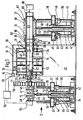
- Fig. 1 eine teilweise im Schnitt dargestellte Seitenansicht eines Ausführungsbeispiels;
- Fig. 2 eine Ansicht in Richtung des Pfeiles II in Fig.l;
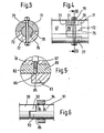
- Fig. 3 einen vergrößert dargestellten Schnitt nach der Linie III - III in Fig.l;
- Fig. 4 eine Seitenansicht der in Fig.3 im Schnitt dargestellten Verbindung der Wellenenden;
- Fig. 5 einen vergrößerten Ausschnitt der Verbindung des Abtriebsendes der Trägerwelle mit der in Fig.1 rechten Lagerwelle;
- Fig. 6 ein abgewandeltes Ausführungsbeispiel der Verbindung von zwei Wellenenden für die Vorrichtung nach Fig.l.
- Fig. 1 is a side view, partially in section, of an embodiment;
- Fig. 2 is a view in the direction of arrow II in Fig.l;
- Fig. 3 is an enlarged section along the line III - III in Fig.l;
- 4 shows a side view of the connection of the shaft ends shown in section in FIG. 3;
- 5 shows an enlarged detail of the connection of the output end of the carrier shaft to the right bearing shaft in FIG. 1;
- 6 shows a modified embodiment of the connection of two shaft ends for the device according to FIG.
Die in den Fig. 1 bis 5 dargestellte Vorrichtung dient zum Herstellen von durchgehenden Einschnitten in zwei kreiszylindrische Halbschalen 11 und 12 mittels eines Lasers 13, der längs einer Führung 14 parallel zur Achse 15 der Halbschalen 11 und 12 vertikal über dieser geführt und über eine in der Zeichnung nicht dargestellte Spindel von einem Motor 16 bewegbar ist. Die Führung 14 und der Motor 16 werden von einem hinter der Vorrichtung angeordneten Ständer 17 getragen.The device shown in FIGS. 1 to 5 is used to produce continuous incisions in two circular cylindrical half-
Die Halbschalen 11 und 12 bestehen aus Sperrholz. Durch den Strahl des Lasers 13 werden in die Halbschalen die durchgehenden Einschnitte ausgebrannt, die zur Aufnahme von Messern dienen. Diese Halbschalen 11 und 12 werden dann auf einer Walze befestigt. Diese Walze wirkt dann mit einer Gegenwalze zusammen, so daß aus Kartonbögen, die durch den Walzp-nspalt hindurchgeführt werden, im Durchlauf Kartonzuschnitte ausgeschnitten werden. Die ausgebrannten Einschnitte können auch dazu verwendet werden, daß außer den Messern auch Werkzeuge zum Einprägen von Rillen eingesetzt werden, so daß im Rotationsverfahren die ausgeschnittenen oder ausgestanzten Kartonzuschnitte gleichzeitig mit Faltrillen versehen werden.The half-
Um diese Einschnitte in die Halbschalen 11 und 12 möglichst schnell und einfach erzeugen zu können, ist unter der Führung 14 des Lasers 13 eine hohle Trägerwelle 18 zwischen zwei in Fig.1 als Ganzes mit 19 und 21 bezeichneten Lagerböcken gelagert. Zum Befestigen der Lagerschalen 11 und 12 sind in der Nähe der beiden Enden der Trägerwelle 18 zwei Lagerräder 22 und 23 befestigt, von denen das eine Lagerrad 23 axial verschiebbar und auf der Trägerwelle 18 mittels einer Klemmvorrichtung 24 festklemmbar ist, die durch Handgriffe 25, von denen in der Zeichnung nur einer dargestellt ist, betätigbar ist. Es handelt sich hierbei um eine bekannte, einen einschraubbaren Kegelstumpf benutzende Klemmvorrichtung, die daher im einzelnen weder dargestellt noch beschrieben ist. Jedes Lagerrad 22 und 23 ist mit einer felgenartigen Verbreiterung 26 versehen, die mit radialen Hohlgewinden versehen ist, die zur Aufnahme von Befestigungsschrauben dienen, mittels deren die Schalen 11 und 12 an den Rädern 22 und 23 befestigt werden können.In order to be able to produce these incisions in the half-
Außerdem sind zwischen den Rädern 22 und 23 noch Speichen 27 vorgesehen, die ebenfalls dazu dienen, die Schalen 11 und 142 mit der Trägerwelle 18 durch Schrauben zu verbinden.In addition,
. Um den ringförmigen Zwischenraum 28 zwischen den Halbschalen 11 und 12-und der Trägerwelle 18 nach außen abzuschließen, sind außerhalb der zur Verringerung der Trägheitsmasse mit Löchern versehenen Lagerräder 22 und 23 Deckscheiben 29 und 31 vorgesehen.. In order to close off the
Die Trägerwelle 18 hat radiale Bohrungen 32, die den Zwischenraum 28 mit dem Hohlraum 33 der Trägerwelle verbinden.The
Das mit der benachbarten Deckscheibe 31 verbundene und axial verschiebbare Lagerrad 23 ist mit dem benachbarten Ende der Trägerwelle 18 mit einem die Trägerwelle 18 umfassenden Faltenbalg 30 verbunden, der dazu dient, die beim Verschieben des Lagerrades nicht mehr in den Zwischenraum 28 mündenden Radialbohrungen 32 mit diesem zu verbinden.The connected to the
Jeder der beiden Lagerböcke 19 und 21 ist mittels eines hydraulischen Zylinders 34 bzw. 35 auf und ab bewegbar und weist zu diesem Zweck einen in vier vertikalen Säulen 36 geführten Rahmen 37 bzw. 3A auf.Each of the two
Koaxial zu den Zylindern 34 und 35 ist eine Rastensäule 39 bzw. 41 angeordnet, die an ihrem Außenumfang mit Rastaussparungen 42 versehen ist, in die ein Riegel 43 in seiner Riegelstellung eingreift, aus der er beim Heben des Lagerbockes 19 bzw.. 21 durch entsprechend geneigte Begrenzungsflächen der Rastaussparung gegen die Kraft einer Feder 44 in eine Entriegelungsstellung herausgedrückt und in dieser durch einen Elektromagneten 45 gehalten wird. Die durch den Riegel 43, die Feder 44 und den Elektromagneten 45 gebildete Riegelvorrichtung ist in einem am Rahmen 37 bzw. 38 befestigten, die Restensäule 39 bzw. 41 umfassenden Ring 46 angeordnet.Coaxial with the
Die Rahmen 37 und 38 der Lagerböcke 19 und 21 tragen Drehlagerungen für die Trägerwelle 18. Die Drehlagerung des Lagerbockes 19 weist eine Lagerwelle 47 auf, die in Lagern 48 drehbar und axial nicht verschiebbar gelagert ist. Die Lager 48 sind auf einer Plattform 49 angeordnet, die mittels eines Gestänges 51 mit dem Rahmen 37 und mittels einer Stellvorrichtung 52 mit der Kolbenstange 53 des hydraulischen Zylinders 34 verbunden. Die Stellvorrichtung 52 dient dazu, die Lage der Plattform gegenüber der Kolbenstange 53 genau justieren zu können. An der Plattform 49 ist eine inkrementale Winkelmeßeinrichtung 54 befestigt, die den Drehwinkel der Lagerwelle 47 mißt, deren Ausgang mit einem Rechner 55 verbunden ist, der auch mit dem Ausgang einer inkrementalen Längenmeßeinrichtung 20 verbunden ist, die dem Rechner die Position des Lasers 13 angibt.The
Auf der Lagerwelle 47 ist ein Zahnrad 56 befestigt, das für den Antrieb durch einen in Fig.1 weggelassenen Zahnriemen 57 dient, der vom Ritzel 58 eines Motors 59 antreibbar ist. Zum Spannen des Zahnriemens 57 ist eine Spannrolle 61 vorgesehen. Der Motor 59 ist zur Aufnahme von Steuersignalen, ebenso wie der Antriebsmotor des Lasers 13, mit dem Rechner 55 verbunden.On the bearing
Ähnlich wie die Kolbenstange 53 des Zylinders 34 mit der Plattform 49 des Lagerbockes 19 ist die Kolbenstange 64 des Zylinders 35 über eine Stellvorrichtung 62 mit einem Lager 68 verbunden, das mit dem Rahmen 38 durch ein Gestell 60 verbunden ist und in dem eine hohle Lagerwelle 67 drehbar und axial unverschiebbar gelagert ist. Die Lagerwelle 67 hat den gleichen Durchmesser wie die Trägerwelle 18. Ihr von der Trägerwelle 18 abgekehrtes Ende ist Ober einen in der Zeichnung nur schematisch angedeutetem Saugschlauch 65 mit einer Absaugvorrichtung 66 verbunden, mittels deren aus dem Zwischenraum 28 beim Einschneiden von durchgehenden Einschnitten in die Halbschalen 11 und 12 entstehende Rauchgase durch die radialen Bohrungen 32, die Hohlräume 33 und 63 der Trägerwelle 18 bzw. Lagerwelle 67 abgesaugt werden können.Similar to the
In den Fig.3 und 4 ist die Verbindung der Enden der Lagerwelle 47 des Lagerbockes 19 mit der Trägerwelle 18 dargestellt. Die beiden zu verbindenden Wellenenden bestehen aus einem Vollmaterial. In das Ende der Lagerwelle 47 ist eine zur Lagerwellenachse koaxiale Sackbohrung 70 gebohrt. Anschließend ist von diesem Ende der Lagerwelle 47 ein Zylindersegment 71 längs einer Diametralebene 72 und einer mit dem Boden der Sackbohrung 70 fluchtenden Radialebene herausgeschnitten.3 and 4, the connection of the ends of the bearing
Die Trägerwelle 18 ist für die Verbindung mit der Lagerwelle 47 mit einem Anschlußstück 74 aus Vollmaterial verbunden, das den Hohlraum der Trägerwelle 18 an diesem Ende verschließt. Dieses Anschlußstück 74 weist einen zur Trägerwelle koaxialen Wellenstumpf 75 auf, der an seinem Ende mit einem Zapfen 76 versehen ist, der im wesentlichen die gleiche-Länge und den gleichen Durchmesser wie die Sackbohrung 70 aufweist.The
In der in Fig.3 dargestellten Drehstellung bildet das verbliebene Zylindersegment 77 der Lagerwelle 47 eine nach oben offene Lagerschale für den Zapfen 76 der Trägerwelle 18, so daß dieser Zapfen von oben in die Schale eingesetzt werden kann. Setzt man anschließend das herausge- _ schnittene Zylindersegment 71 wieder ein und verbindet es mit dem Zapfen 76 und dem verbliebenen Zylindersegment 77 mittels einer Schraube 79, dann erhält man dadurch eine sehr leicht lösbare und einwandfreie drehfeste Verbindung zwischen den beiden Wellenenden.In the rotational position shown in FIG. 3, the remaining
Eine ähnliche Verbindung ist zwischen dem hohlen Ende der Trägerwelle 18 und dem hohlen Ende der Lagerwelle 67 vorgesehen. Zu diesem Zweck ist das betreffende Ende der Lagerwelle 67 mit einem koaxialen Rohrstutzen 80 verbunden, aus dessen freiem Ende, ebenso wie aus dem Ende der Lagerwelle 47, ein Zylindersegment 81 herausgeschnitten ist, so daß das verbliebene Zylindersegment 82 in der in Fig.1 dargestellten Drehstellung der Lagerwelle 67 eine nach oben offene Mulde bildet.A similar connection is provided between the hollow end of the
Auf dem Rohrstutzen 80 ist eine Deckhülse 83 verschiebbar gelagert, die zwei umlaufende Innennuten 84 und 85 für eine gefederte Rastkugel 86 aufweist. Die Rastkugel ist im Rohrstutzen 80 so angeordnet, daß die Deckhülse 83 in ihrer Freigabestellung (Fig.5) so gehalten ist, daß der Zylindersegmentausschnitt offen ist und die Trägerwelle 18 von oben in die durch das verbliebene Zylindersegment 82 gebildete Mulde eingesetzt werden kann. Wird dann das ausgeschnittene Zylindersegment 81 in den Zylindersegmentausschnitt eingelegt und die Deckhülse aus der Freigabestellung in ihre, das Ende der Haltewelle und das verbliebene Zylindersegment umfassende Deckstellung bis zum Einrasten der Rastkugel in die zweite Innennut 84 verschoben (Fig.1), dann werden die beiden Wellenenden koaxial zusammengehalten. Auf Drehung sind sie nur durch die durch das Gewicht der Trägerwelle verursachte Reibung kraftschlüssig miteinander verbunden. Im vorliegenden Fall ist jedoch eine formschlüssige Verbindung nicht notwendig, da diese Verbindung lediglich ausreichen soll, um die Trägerwelle zu tragen und eine Absaugung des Zwischenraumes 28 zu ermöglichen.On the
In Fig.6 ist noch eine weitere formschlüssige Verbindung zwischen den Enden der Trägerwelle und den benachbarten Enden der Lagerwelle an Hand einer Verbindung dargestellt. Die Zeichnung zeigt die Verbindung von zwei Wellenenden 90 und 91 aus Vollmaterial mit gleichem Durchmesser. Das gleiche gilt für zwei hohle Wellenenden, wenn diese den gleichen Durchmesser haben. In beide zu verbindende Wellenenden 90 und 91 wird, wie oben beschrieben, je ein gleiches Zylindersegment herausgeschnitten. Die Wellen sind so aneinandergefügt, daß die verbliebenen Zylindersegmente 92 bzw. 93 mit ihren ebenen Diametralflächen aneinanderliegen. Eine der Deckhülse 83 entsprechende Deckhülse 94 ist mit einer Rastkugel arretierbar aus einer Freigabestellung (Fig.6) auf dem Wellenende 91 in eine Deckstellung verschiebbar, in der sie die beiden Wellenenden koaxial miteinander verbindet, so daß diese infolge der Anlage der beiden Diametralebenen aneinander formschlüssig miteinander verbunden sind.6 shows yet another positive connection between the ends of the carrier shaft and the adjacent ends of the bearing shaft by means of a connection. The drawing shows the connection of two shaft ends 90 and 91 made of solid material with the same diameter. The same applies to two hollow shaft ends if they have the same diameter. As described above, an identical cylinder segment is cut out in both shaft ends 90 and 91 to be connected. The shafts are joined together in such a way that the remaining
Mit der dargestellten Vorrichtung können Einschnitte in die Halbschalen 11 und 12 mittels des Lasers 13 dadurch hergestellt werden, daß die Positionen des Lasers auf seiner Bahn und die Winkelstellungen der Trägerwelle 18 und damit der Schalen 11 durch die inkrementalen Positionsmeßeinrichtungen, nämlich die inkrementale Lä'ngenmeßeinrich- tung 20 und die inkrementale Winkelmeßeinrichtung 54, gemessen und die gemessenen Werte in den Rechner 55 eingegeben werden, der nach einem Programm die Steuerung der Motoren 16 bzw. 59 zum Herstellen von Einschnitten mit einem vorbestimmten Verlauf miteinander koordiniert.With the device shown, incisions in the half-
Da mit den bekannten Lasern 13 eine Tastvorrichtung verbunden ist, die die zu bearbeitende Oberfläche abtastet und dafür sorgt, daß der Laser immer den gleichen Abstand von der Oberfläche hat, können mit der beschriebenen und dargestellten Vorrichtung nicht nur kreiszylindrische Oberflächen, sondern auch unregelmäßige Oberflächen, insbesondere Rotationsflächen bearbeitet werden, die verschiedene Durchmesser haben, durch die der Abstand von der Laserbahn nicht Ober die durch die Tastvorrichtung ermöglichte Einstellung des Lasers hinausgeht.Since a scanner is connected to the known
Mittels der Zylinder 34 und 35 kann die dargestellte Vorrichtung nicht nur für durch die Rastaussparungen 42 bestimmte Durchmesser der Rotationsflächen eingestellt werden, sondern auch für Zwischenwerte. Die Rasteinrichtung dient vor allem dazu, daß, wenn durch ein plötzliches Ereignis der Druck des Druckmittels im Zylinder nachgeben sollte, die Lagerböcke 19 und 21 nicht um den ganzen Hub des Zylinders herunterstürzen, sondern durch die Rasteinrichtung durch den Eingriff in die nächste Rastaussparung 42 abgefangen werden.By means of the
Dadurch, daß die Kraft des Magneten nur dazu ausreicht, den Riegel 43 in der entriegelten Stellung zu halten und nicht aus der Riegelstellung herauszuheben, wird ein Unfall durch ein unsachgemäßes Betätigen des Elektromagneten vermieden.Because the force of the magnet is only sufficient to hold the
Alle in der vorstehenden Beschreibung erwähnten sowie auch die nur allein aus der Zeichnung entnehmbaren Merkmale sind als weitere Ausgestaltungen Bestandteile der Erfindung, auch wenn sie nicht besonders hervorgehoben und insbesondere nicht in den Ansprüchen erwähnt sind.All of the features mentioned in the above description and also the features that can only be inferred from the drawing are further refinements of the invention, even if they are not particularly emphasized and are not mentioned in the claims.
Claims (22)
Priority Applications (1)
| Application Number | Priority Date | Filing Date | Title |
|---|---|---|---|
| AT87102289T ATE59318T1 (en) | 1986-04-25 | 1987-02-18 | DEVICE FOR PROCESSING A BODY WITH CYLINDRICAL SURFACE BY MEANS OF A LASER. |
Applications Claiming Priority (2)
| Application Number | Priority Date | Filing Date | Title |
|---|---|---|---|
| DE19863614082 DE3614082A1 (en) | 1986-04-25 | 1986-04-25 | DEVICE AND METHOD FOR MAKING CUTS IN THE EXTERNAL SURFACES OF AT LEAST ONE BODY |
| DE3614082 | 1986-04-25 |
Publications (2)
| Publication Number | Publication Date |
|---|---|
| EP0244574A1 true EP0244574A1 (en) | 1987-11-11 |
| EP0244574B1 EP0244574B1 (en) | 1990-12-27 |
Family
ID=6299555
Family Applications (1)
| Application Number | Title | Priority Date | Filing Date |
|---|---|---|---|
| EP87102289A Expired - Lifetime EP0244574B1 (en) | 1986-04-25 | 1987-02-18 | Device for the treatment of a body having a cylindrical surface by using a laser |
Country Status (6)
| Country | Link |
|---|---|
| US (1) | US4742206A (en) |
| EP (1) | EP0244574B1 (en) |
| AT (1) | ATE59318T1 (en) |
| DE (2) | DE3614082A1 (en) |
| ES (1) | ES2019308B3 (en) |
| GR (1) | GR3001251T3 (en) |
Cited By (3)
| Publication number | Priority date | Publication date | Assignee | Title |
|---|---|---|---|---|
| US5653900A (en) * | 1991-01-17 | 1997-08-05 | United Distillers Plc | Dynamic laser marking |
| US6791592B2 (en) | 2000-04-18 | 2004-09-14 | Laserink | Printing a code on a product |
| US10583668B2 (en) | 2018-08-07 | 2020-03-10 | Markem-Imaje Corporation | Symbol grouping and striping for wide field matrix laser marking |
Families Citing this family (10)
| Publication number | Priority date | Publication date | Assignee | Title |
|---|---|---|---|---|
| US5073694A (en) * | 1991-02-21 | 1991-12-17 | Synthes (U.S.A.) | Method and apparatus for laser cutting a hollow metal workpiece |
| US5493095A (en) * | 1994-02-14 | 1996-02-20 | Data Technology, Inc. | Laser beam divergence compensation apparatus |
| IT1287906B1 (en) * | 1996-05-22 | 1998-08-26 | L C G Srl | CUTTING UNIT FOR CONTINUOUSLY PRODUCED PIPES |
| US5994667A (en) * | 1997-10-15 | 1999-11-30 | Scimed Life Systems, Inc. | Method and apparatus for laser cutting hollow workpieces |
| IT1308986B1 (en) * | 1999-01-28 | 2002-01-15 | Sacmi | MACHINE FOR CUTTING THE CYLINDRICAL WALL OF PLASTIC CAPS TO FORM A FRACTURE LINE SUITABLE TO PROMOTE THE DETACHMENT OF A |
| JP3607259B2 (en) * | 2002-04-16 | 2005-01-05 | ヤマザキマザック株式会社 | 3D linear processing equipment |
| US20050088510A1 (en) * | 2003-10-24 | 2005-04-28 | Shlomo Assa | Low angle optics and reversed optics |
| US7046267B2 (en) * | 2003-12-19 | 2006-05-16 | Markem Corporation | Striping and clipping correction |
| US7394479B2 (en) | 2005-03-02 | 2008-07-01 | Marken Corporation | Pulsed laser printing |
| US7353612B1 (en) | 2005-12-27 | 2008-04-08 | World-B Enterprises, L.L.C. | Laser system and method for alignment of tooling onto corrugated box cutting machines |
Citations (2)
| Publication number | Priority date | Publication date | Assignee | Title |
|---|---|---|---|---|
| DE2950149A1 (en) * | 1979-12-13 | 1981-06-19 | R + S Stanzformen GmbH, 6000 Frankfurt | Cutting of notches in plywood base-plate - employs hollow, notched cylindrical drum under laser cutting set with drive wheel mounted on drum shaft |
| EP0072609A1 (en) * | 1981-06-22 | 1983-02-23 | Zed Instruments Limited | Improvement in or relating to methods and apparatus for laser engraving |
Family Cites Families (3)
| Publication number | Priority date | Publication date | Assignee | Title |
|---|---|---|---|---|
| JPS5269091A (en) * | 1975-12-05 | 1977-06-08 | Nec Corp | Laser working device |
| US4427872A (en) * | 1978-09-22 | 1984-01-24 | Coherent, Inc. | Precision machining apparatus and method utilizing a laser |
| LU80792A1 (en) * | 1979-01-15 | 1980-08-08 | Ntre De Rech Metallurg Ct Voor | DISPSITIVE AND METHOD FOR PERFORMING PERFORATIONS ON THE SURFACE OF ROLLING MILLS |
-
1986
- 1986-04-25 DE DE19863614082 patent/DE3614082A1/en not_active Withdrawn
-
1987
- 1987-02-18 ES ES87102289T patent/ES2019308B3/en not_active Expired - Lifetime
- 1987-02-18 EP EP87102289A patent/EP0244574B1/en not_active Expired - Lifetime
- 1987-02-18 AT AT87102289T patent/ATE59318T1/en not_active IP Right Cessation
- 1987-02-18 DE DE8787102289T patent/DE3767021D1/en not_active Expired - Fee Related
- 1987-04-17 US US07/039,212 patent/US4742206A/en not_active Expired - Fee Related
-
1990
- 1990-12-28 GR GR90401057T patent/GR3001251T3/en unknown
Patent Citations (2)
| Publication number | Priority date | Publication date | Assignee | Title |
|---|---|---|---|---|
| DE2950149A1 (en) * | 1979-12-13 | 1981-06-19 | R + S Stanzformen GmbH, 6000 Frankfurt | Cutting of notches in plywood base-plate - employs hollow, notched cylindrical drum under laser cutting set with drive wheel mounted on drum shaft |
| EP0072609A1 (en) * | 1981-06-22 | 1983-02-23 | Zed Instruments Limited | Improvement in or relating to methods and apparatus for laser engraving |
Cited By (4)
| Publication number | Priority date | Publication date | Assignee | Title |
|---|---|---|---|---|
| US5653900A (en) * | 1991-01-17 | 1997-08-05 | United Distillers Plc | Dynamic laser marking |
| US6791592B2 (en) | 2000-04-18 | 2004-09-14 | Laserink | Printing a code on a product |
| US6829000B2 (en) | 2000-04-18 | 2004-12-07 | Laserink | Printing a code on a product |
| US10583668B2 (en) | 2018-08-07 | 2020-03-10 | Markem-Imaje Corporation | Symbol grouping and striping for wide field matrix laser marking |
Also Published As
| Publication number | Publication date |
|---|---|
| DE3767021D1 (en) | 1991-02-07 |
| DE3614082A1 (en) | 1987-10-29 |
| EP0244574B1 (en) | 1990-12-27 |
| GR3001251T3 (en) | 1992-08-25 |
| ATE59318T1 (en) | 1991-01-15 |
| US4742206A (en) | 1988-05-03 |
| ES2019308B3 (en) | 1991-06-16 |
Similar Documents
| Publication | Publication Date | Title |
|---|---|---|
| EP0970770B1 (en) | Apparatus and method for working drill holes | |
| EP0244574B1 (en) | Device for the treatment of a body having a cylindrical surface by using a laser | |
| DE4234115A1 (en) | CAN SEALING MACHINE | |
| DE2602262B2 (en) | Device for the folding of cup-shaped, metal workpieces, in particular Dosenriimpfen and the like | |
| DE3441821A1 (en) | KNIFE HEAD | |
| CH657567A5 (en) | REVOLVER PUNCH. | |
| EP3017909A1 (en) | Adjusting device for a printing roller of a processing machine, in particular a moulder, and processing machine, in particular moulder, with such an adjustment device | |
| DE3131107A1 (en) | Device for adjusting the axis of rotation of a joint for the swivellable suspension of a radius arm of a wheel on the body of a motor vehicle | |
| EP0120302B1 (en) | Universal milling head for machine tools | |
| DE1577366B1 (en) | Cylindrical grinding machine for the simultaneous processing of two rotating workpieces with one rotating tool | |
| DE2931970C2 (en) | Cutting device for longitudinal cutting of a paper web | |
| DE4406597A1 (en) | Adjustable wall cutting attachment | |
| DE2559145B2 (en) | Deburring tool | |
| DE4308419C2 (en) | Tool turret | |
| DE3239720T1 (en) | INTERNAL GRINDING MACHINE | |
| DE3708341A1 (en) | Feeding device to be used in connection with woodworking machines for feeding the workpiece | |
| DE8611435U1 (en) | Device for making incisions in the outer surfaces of at least one body | |
| DE3539335C2 (en) | ||
| EP0800877A1 (en) | Thread rolling head | |
| DE3116389C2 (en) | Self-propelled flame cutting machine for bevel cuts | |
| DE3247672C2 (en) | Adjustable beveling cutter head | |
| DE19943776A1 (en) | Ritz circular saw | |
| DE1477040A1 (en) | Tool holder for rolling tools | |
| DE1627381B2 (en) | PORTABLE DEVICE FOR THREADING ON PIPES OR DGL. | |
| DE1561413C3 (en) | Scoring and slitting device equipped with tools that work together in pairs |
Legal Events
| Date | Code | Title | Description |
|---|---|---|---|
| PUAI | Public reference made under article 153(3) epc to a published international application that has entered the european phase |
Free format text: ORIGINAL CODE: 0009012 |
|
| AK | Designated contracting states |
Kind code of ref document: A1 Designated state(s): AT BE CH DE ES FR GB GR IT LI LU NL SE |
|
| 17P | Request for examination filed |
Effective date: 19880414 |
|
| 17Q | First examination report despatched |
Effective date: 19890712 |
|
| GRAA | (expected) grant |
Free format text: ORIGINAL CODE: 0009210 |
|
| AK | Designated contracting states |
Kind code of ref document: B1 Designated state(s): AT BE CH DE ES FR GB GR IT LI LU NL SE |
|
| REF | Corresponds to: |
Ref document number: 59318 Country of ref document: AT Date of ref document: 19910115 Kind code of ref document: T |
|
| GBT | Gb: translation of ep patent filed (gb section 77(6)(a)/1977) | ||
| REF | Corresponds to: |
Ref document number: 3767021 Country of ref document: DE Date of ref document: 19910207 |
|
| ET | Fr: translation filed | ||
| ITF | It: translation for a ep patent filed |
Owner name: MODIANO & ASSOCIATI S.R.L. |
|
| PLBE | No opposition filed within time limit |
Free format text: ORIGINAL CODE: 0009261 |
|
| STAA | Information on the status of an ep patent application or granted ep patent |
Free format text: STATUS: NO OPPOSITION FILED WITHIN TIME LIMIT |
|
| 26N | No opposition filed | ||
| REG | Reference to a national code |
Ref country code: GR Ref legal event code: FG4A Free format text: 3001251 |
|
| PGFP | Annual fee paid to national office [announced via postgrant information from national office to epo] |
Ref country code: GB Payment date: 19930205 Year of fee payment: 7 |
|
| PGFP | Annual fee paid to national office [announced via postgrant information from national office to epo] |
Ref country code: CH Payment date: 19930208 Year of fee payment: 7 |
|
| PGFP | Annual fee paid to national office [announced via postgrant information from national office to epo] |
Ref country code: ES Payment date: 19930211 Year of fee payment: 7 |
|
| PGFP | Annual fee paid to national office [announced via postgrant information from national office to epo] |
Ref country code: LU Payment date: 19930212 Year of fee payment: 7 |
|
| PGFP | Annual fee paid to national office [announced via postgrant information from national office to epo] |
Ref country code: AT Payment date: 19930215 Year of fee payment: 7 |
|
| PGFP | Annual fee paid to national office [announced via postgrant information from national office to epo] |
Ref country code: SE Payment date: 19930216 Year of fee payment: 7 |
|
| PGFP | Annual fee paid to national office [announced via postgrant information from national office to epo] |
Ref country code: GR Payment date: 19930217 Year of fee payment: 7 |
|
| PGFP | Annual fee paid to national office [announced via postgrant information from national office to epo] |
Ref country code: FR Payment date: 19930225 Year of fee payment: 7 |
|
| PGFP | Annual fee paid to national office [announced via postgrant information from national office to epo] |
Ref country code: NL Payment date: 19930228 Year of fee payment: 7 |
|
| PGFP | Annual fee paid to national office [announced via postgrant information from national office to epo] |
Ref country code: BE Payment date: 19930305 Year of fee payment: 7 |
|
| PGFP | Annual fee paid to national office [announced via postgrant information from national office to epo] |
Ref country code: DE Payment date: 19930401 Year of fee payment: 7 |
|
| EPTA | Lu: last paid annual fee | ||
| PG25 | Lapsed in a contracting state [announced via postgrant information from national office to epo] |
Ref country code: LU Free format text: LAPSE BECAUSE OF NON-PAYMENT OF DUE FEES Effective date: 19940218 Ref country code: GB Effective date: 19940218 Ref country code: AT Effective date: 19940218 |
|
| PG25 | Lapsed in a contracting state [announced via postgrant information from national office to epo] |
Ref country code: SE Effective date: 19940219 Ref country code: ES Free format text: LAPSE BECAUSE OF NON-PAYMENT OF DUE FEES Effective date: 19940219 |
|
| PG25 | Lapsed in a contracting state [announced via postgrant information from national office to epo] |
Ref country code: LI Effective date: 19940228 Ref country code: CH Effective date: 19940228 Ref country code: BE Effective date: 19940228 |
|
| BERE | Be: lapsed |
Owner name: ELCEDE G.M.B.H. Effective date: 19940228 |
|
| PG25 | Lapsed in a contracting state [announced via postgrant information from national office to epo] |
Ref country code: GR Free format text: THE PATENT HAS BEEN ANNULLED BY A DECISION OF A NATIONAL AUTHORITY Effective date: 19940831 |
|
| PG25 | Lapsed in a contracting state [announced via postgrant information from national office to epo] |
Ref country code: NL Effective date: 19940901 |
|
| GBPC | Gb: european patent ceased through non-payment of renewal fee |
Effective date: 19940218 |
|
| NLV4 | Nl: lapsed or anulled due to non-payment of the annual fee | ||
| PG25 | Lapsed in a contracting state [announced via postgrant information from national office to epo] |
Ref country code: FR Effective date: 19941031 |
|
| REG | Reference to a national code |
Ref country code: CH Ref legal event code: PL |
|
| PG25 | Lapsed in a contracting state [announced via postgrant information from national office to epo] |
Ref country code: DE Effective date: 19941101 |
|
| REG | Reference to a national code |
Ref country code: FR Ref legal event code: ST Ref country code: GR Ref legal event code: MM2A Free format text: 3001251 |
|
| EUG | Se: european patent has lapsed |
Ref document number: 87102289.3 Effective date: 19940910 |
|
| REG | Reference to a national code |
Ref country code: ES Ref legal event code: FD2A Effective date: 19990201 |
|
| PG25 | Lapsed in a contracting state [announced via postgrant information from national office to epo] |
Ref country code: IT Free format text: LAPSE BECAUSE OF NON-PAYMENT OF DUE FEES;WARNING: LAPSES OF ITALIAN PATENTS WITH EFFECTIVE DATE BEFORE 2007 MAY HAVE OCCURRED AT ANY TIME BEFORE 2007. THE CORRECT EFFECTIVE DATE MAY BE DIFFERENT FROM THE ONE RECORDED. Effective date: 20050218 |