EP0244350B1 - Frame for platform or box freight lorries comprising transversely arranged floorboards - Google Patents
Frame for platform or box freight lorries comprising transversely arranged floorboards Download PDFInfo
- Publication number
- EP0244350B1 EP0244350B1 EP87810147A EP87810147A EP0244350B1 EP 0244350 B1 EP0244350 B1 EP 0244350B1 EP 87810147 A EP87810147 A EP 87810147A EP 87810147 A EP87810147 A EP 87810147A EP 0244350 B1 EP0244350 B1 EP 0244350B1
- Authority
- EP
- European Patent Office
- Prior art keywords
- grooves
- frame according
- floor boards
- cross
- aluminium
- Prior art date
- Legal status (The legal status is an assumption and is not a legal conclusion. Google has not performed a legal analysis and makes no representation as to the accuracy of the status listed.)
- Expired - Lifetime
Links
- 229910052782 aluminium Inorganic materials 0.000 claims abstract description 23
- XAGFODPZIPBFFR-UHFFFAOYSA-N aluminium Chemical compound [Al] XAGFODPZIPBFFR-UHFFFAOYSA-N 0.000 claims abstract description 19
- 210000002105 tongue Anatomy 0.000 claims abstract description 12
- 239000004411 aluminium Substances 0.000 claims abstract 7
- 239000010410 layer Substances 0.000 claims description 7
- 239000002131 composite material Substances 0.000 claims description 5
- 239000012792 core layer Substances 0.000 claims description 3
- 239000011120 plywood Substances 0.000 claims description 2
- 239000002245 particle Substances 0.000 claims 1
- 239000002023 wood Substances 0.000 claims 1
- 239000000853 adhesive Substances 0.000 description 6
- 230000001070 adhesive effect Effects 0.000 description 6
- 238000010276 construction Methods 0.000 description 5
- 239000000463 material Substances 0.000 description 4
- 238000012360 testing method Methods 0.000 description 4
- 230000007797 corrosion Effects 0.000 description 3
- 238000005260 corrosion Methods 0.000 description 3
- 239000006260 foam Substances 0.000 description 3
- 238000010422 painting Methods 0.000 description 3
- XEEYBQQBJWHFJM-UHFFFAOYSA-N Iron Chemical group [Fe] XEEYBQQBJWHFJM-UHFFFAOYSA-N 0.000 description 2
- 238000005265 energy consumption Methods 0.000 description 2
- 238000004026 adhesive bonding Methods 0.000 description 1
- 230000004888 barrier function Effects 0.000 description 1
- 238000009792 diffusion process Methods 0.000 description 1
- 238000006073 displacement reaction Methods 0.000 description 1
- 230000000694 effects Effects 0.000 description 1
- 150000002505 iron Chemical class 0.000 description 1
- 229910052742 iron Inorganic materials 0.000 description 1
- DMKSVUSAATWOCU-HROMYWEYSA-N loteprednol etabonate Chemical compound C1CC2=CC(=O)C=C[C@]2(C)[C@@H]2[C@@H]1[C@@H]1CC[C@@](C(=O)OCCl)(OC(=O)OCC)[C@@]1(C)C[C@@H]2O DMKSVUSAATWOCU-HROMYWEYSA-N 0.000 description 1
- 238000012423 maintenance Methods 0.000 description 1
- 238000004519 manufacturing process Methods 0.000 description 1
- 238000005259 measurement Methods 0.000 description 1
- 230000008092 positive effect Effects 0.000 description 1
- 239000007787 solid Substances 0.000 description 1
- 239000004575 stone Substances 0.000 description 1
Images


Classifications
-
- B—PERFORMING OPERATIONS; TRANSPORTING
- B62—LAND VEHICLES FOR TRAVELLING OTHERWISE THAN ON RAILS
- B62D—MOTOR VEHICLES; TRAILERS
- B62D33/00—Superstructures for load-carrying vehicles
- B62D33/04—Enclosed load compartments ; Frameworks for movable panels, tarpaulins or side curtains
- B62D33/044—Enclosed load compartments ; Frameworks for movable panels, tarpaulins or side curtains built up with profiles of constant elongated shape, e.g. extruded, mechanically interconnected by coupling members, e.g. by clamping, riveting or bolting
-
- B—PERFORMING OPERATIONS; TRANSPORTING
- B62—LAND VEHICLES FOR TRAVELLING OTHERWISE THAN ON RAILS
- B62D—MOTOR VEHICLES; TRAILERS
- B62D25/00—Superstructure or monocoque structure sub-units; Parts or details thereof not otherwise provided for
- B62D25/20—Floors or bottom sub-units
- B62D25/2054—Load carrying floors for commercial vehicles
Definitions
- the invention relates to a chassis for platform or box vehicles of the construction specified in the preamble of claim 1. Street vehicles with an aluminum chassis have been in use for twenty years. With an aluminum chassis, depending on the type of trailer or semi-trailer and its dimensions, a weight saving of 200 to 1000 kg is achieved. Further decisive advantages are the corrosion resistance, the low maintenance costs, the longer service life and the lower energy consumption.
- an aluminum chassis can be fitted with transverse or longitudinally laid aluminum floor planks, made from extruded profiles, or wooden-based floor plates.
- Chassis types and floor planks or floor plates are adapted to the total weight and the application and have a smooth or corrugated loading surface.
- the platform floor can be driven on with forklifts and hand pallet trucks.
- Cross-laid aluminum floor planks made of extruded profiles are fastened to the side members and the outer frames running in the longitudinal direction of the vehicle using clamping pieces. There is no need to perforate the floor planks.
- cross-laid floor panels are screwed onto the longitudinal beams and / or on cross beams running between the floor panels.
- base plates which are solid, the use of clamping pieces is not possible or is uneconomical.
- a construction corresponding to the preamble of claim 1 is known from DE-A 2 522 477.
- two spaced-apart cross members made of bent and welded profiled iron form grooves between them, into which the transverse ends of the base plates are inserted.
- the two profile bars are connected by screwing, the distance corresponding to the thickness of the base plate.
- the disadvantages of this iron construction have already been described above (e.g. greater weight, greater manufacturing effort, less corrosion resistance and thus the need for painting, more individual parts).
- the inventor has therefore set itself the task of creating a chassis for platform or box vehicles according to the preamble of claim 1, which avoids the disadvantages mentioned and allows a simpler and less expensive, but still stable arrangement of the base plates, for which the base plates connecting cross member, extruded aluminum profiles should be used from one piece.
- the cross members are preferably made of extruded aluminum profiles.
- the crossbeams can have grooves extending on both sides over the entire length, in which correspondingly shaped springs of the base plates, which correspond to the grooves in their geometrical shape, engage. It has proven to be advantageous to form only one groove or only one tongue per positive connection point.
- the cross member formed from an extruded aluminum profile can have springs extending on both sides over the entire length of the side faces.
- the side surfaces of the floor panels must have appropriately shaped grooves.
- grooves are preferred which narrow inward in cross section and are, for example, trapezoidal, semicircular or triangular. It goes without saying that the spring to be inserted must have a corresponding geometric shape.
- the base plates can easily be clamped or the like without any screws. be fixed to the cross members.
- the grooves, which preferably narrow inwards, and the correspondingly shaped springs ensure that there is no play during tensioning.
- the grooves and tongues are connected to one another by the use of known adhesives, it being possible for prestressing to take place to a greater or lesser extent.
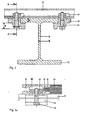
- the longitudinal member 10 shown in FIG. 1 comprises a lower flange 12 and an upper flange 16.
- This longitudinal frame upper flange 16 is connected to the lower flange 12 by means of weld seams 18.
- the cross member 20 is fastened to the longitudinal member upper flange 16 by means of two clamping plates 22.
- the cross member 20 can be freely moved and fixed along the side member 10. Furthermore, when using clamping plates, there is no need to drill through the top flange 16 of the side member.
- a wheel bolt 24 with a corrugated head 26 passes through the cross member 20 and the clamping plate 22 and is tightened by a self-locking nut 28 with washer 30.
- the clamping plate 22 is a special embodiment. In the present case, it can optimally attach a longitudinal girder top chord of thickness a. If the clamping plate 22 is pulled out of the wheel bolt, rotated through 180 ° and reinserted, it develops its optimal effect over a distance b.
- the distance a can be 15 mm, b 20 mm, for example.
- the cross member has a cross section which is in principle similar to a lying H.
- the spring 32 also called a comb, which protrudes from the base plate 34, tapers in the form of an isosceles cross-section.
- the base plate fits into the correspondingly designed lateral groove 36 of the cross member 20.
- the tongue 32 of the braced base plate 34 does not extend all the way to the rearmost end of the groove 36, a small space remains open. This serves to collect adhesive pushed backwards when the base plate 34 is pushed in. All common adhesives, seal material, elastic putty etc. are suitable for gluing, which is advantageously used.
- the crossbeams are 90 mm wide, the base plates 625-750 mm wide.
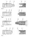
- the cross member 20 with bore 44 has a spring 54 which is guided into a correspondingly adapted groove in the base plate 34.
- the cross member 20 shown in Fig. 5 has a bore 44 for attachment to the side member.
- the groove 36 in the cross member 20 for receiving the tongue 32 of the base plate 34 made of plywood is made substantially smaller than, for example, that in FIG. 2. Nevertheless, the groove 36 and the corresponding tongue 32 are conical.
- the base plate 34 has a completely different structure. It consists of an aluminum-plastic-aluminum composite.
- the cover layer 46 consists of a corrugated aluminum sheet, followed by a layer 48 of a rigid rigid foam, known under the brand name FOREX by Lonza.
- the core layer 50 consists of a coarse-cell foam, known under the brand name AIREX by Lonza.
- a layer 48 made of a rigid rigid foam is again arranged below this core layer 50.
- the composite material is bounded at the bottom by an aluminum sheet 52, which acts as a diffusion barrier and protection against stone chips.
- the aluminum-plastic-aluminum composite is clamped in the groove 36 of the cross member 20.
- the cross member 20 shown in Fig. 7 differs from the previous one. that it shows not a groove, but a tongue 54 in the lateral area.
- the spring is semicircular in cross-section, that is three-dimensionally has the shape of a half cylinder.
- a groove 56 which is semicircular in cross section, is recessed in the base plate 34, into which the spring 54 is inserted during tensioning.
- FIG. 8 shows a perspective view of a longitudinal member 10 and an outer frame 14, on which cross member 20 and base plates 34 are alternately fastened.
- the width of the cross member 20 is preferably between 50 and 100 mm, that of the base plates 34 between 500 and 1500 mm.
Abstract
Description
Die Erfindung bezieht sich auf ein Chassis für Pritschen- oder Kastenfahrzeuge der im Oberbegriff des Anspruchs 1 angegebenen Konstruktion. Seit nunmehr zwanzig Jahren sind Strassenfahrzeuge mit einem Aluminium-Chassis in Gebrauch. Mit einem Aluminium-Chassis wird je nach Anhänger- oder Sattelanhänger-Typ und deren Abmessungen eine Gewichtseinsparung von 200 bis 1000 kg erzielt. Weitere entscheidende Vorteile sind die Korrosionsbeständigkeit, die geringen Unterhaltskosten, die längere Lebensdauer und der kleinere Energieverbrauch.The invention relates to a chassis for platform or box vehicles of the construction specified in the preamble of claim 1. Street vehicles with an aluminum chassis have been in use for twenty years. With an aluminum chassis, depending on the type of trailer or semi-trailer and its dimensions, a weight saving of 200 to 1000 kg is achieved. Further decisive advantages are the corrosion resistance, the low maintenance costs, the longer service life and the lower energy consumption.
Dank umfassender Tests mit Chassis-Trägern und verschiedenen Untersuchungen mit Spannungsmessungen an Fahrzeugen auf Prüfstrecken und langjähriger Praxiserproblung ist es heute möglich, für jeden Fahrzeugtyp und für jedes Transportgut das optimale Aluminium-Chassis anzubieten. Dem Fahrzeughersteller bieten sich für bewährte Chassis-Konstruktionen aus Aluminium u.a. folgende Vorteile an:
- - Einbaufertige Längsträger,
- - wenig Bauteile, daher einfache Materialbewirtschaftung und niedrige Montagezeiten,
- - es ist keine Lackierung erforderlich,
- - die Werkstoffe können rezykliert werden.
- - ready-to-install side members,
- - few components, therefore simple material management and short assembly times,
- - no painting is required,
- - The materials can be recycled.
Auch dem Fahrzeughalter bieten Fahrzeuge mit einem Aluminium-Chassis bedeutende Vorteile:
- - Ein geringeres Eigengewicht lässt eine höhere Nutzlast zu, was eine höhere Wirtschaftlichkeit bedeutet,
- - bei Leerfahrten oder Teillast ist der Energieverbrauch geringer,
- - die hohe Korrosionsbeständigkeit macht eine Lackierung überflüssig, das System ist unterhaltsfreundlich,
- - die robuste Bauweise ermöglicht eine lange Lebensdauer und trägt mit dem hohen Schrottwert weiter zur Wirtschaftlichkeit bei.
- - A lower dead weight allows a higher payload, which means greater economy,
- - the energy consumption is lower during empty runs or partial load,
- - the high corrosion resistance makes painting unnecessary, the system is easy to maintain,
- - The robust design enables a long service life and, with its high scrap value, further contributes to economy.
Für Pritschen- oder Kastenfahrzeuge kann ein Aluminium-Chassis mit quer- oder längsverlegten Aluminiumbodenplanken, hergestellt aus Strangpressprofilen, oder Bodenplatten auf Holzbasis bestückt werden.For flatbed or box vehicles, an aluminum chassis can be fitted with transverse or longitudinally laid aluminum floor planks, made from extruded profiles, or wooden-based floor plates.
Chassis-Typen und Bodenplanken bzw. Bodenplatten sind dem Gesamtgewicht und dem Einsatz entsprechend angepasst und mit einer glatten oder geriffelten Ladefläche versehen. Je nach Einsatz ist der Pritschenboden mit Hubstaplern und Handhubwager befahrbar.Chassis types and floor planks or floor plates are adapted to the total weight and the application and have a smooth or corrugated loading surface. Depending on the application, the platform floor can be driven on with forklifts and hand pallet trucks.
Querverlegte Aluminium-Bodenplanken aus Strangpressprofilen werden mit Klemmstücken an den Längsträgem und den in Längsrichtung des Fahrzeugs verlaufenden Aussenrahmen befestigt. Die Bodenplanken müssen nicht durchlöchert werden.Cross-laid aluminum floor planks made of extruded profiles are fastened to the side members and the outer frames running in the longitudinal direction of the vehicle using clamping pieces. There is no need to perforate the floor planks.
Querverlegte Bodenplatten dagegen werden in den bekannten Ausführungsformen mittels Schrauben an den Längsträgem und/oder an zwischen den Bodenplatten verlaufenden Querträgem angeschraubt. Bei Bodenplatten, welche massiv ausgebildet sind, ist die Verwendung von Klemmstücken nicht möglich oder unwirtschaftlich.In contrast, in the known embodiments, cross-laid floor panels are screwed onto the longitudinal beams and / or on cross beams running between the floor panels. In the case of base plates which are solid, the use of clamping pieces is not possible or is uneconomical.
Eine, dem Oberbegriff von Patentanspruch 1 entsprechende Konstruktion ist aus der DE-A 2 522 477 bekannt. Bei dieser Konstruktion bilden zwei in Abstand übereinander angeordnete Querträger aus gebogenen und geschweissten Profileisen zwischen sich Nuten, in welche die quer verlaufenden Enden der Bodenplatten eingeschoben werden. Die beiden Profileisen werden durch Verschrauben miteinander verbunden, wobei der Abstand der Dicke der Bodenplatte entspricht. Die Nachteile dieser Eisenkonstruktion sind schon oben beschrieben (z.B.: grösseres Gewicht, grösserer Fertigungsaufwand, geringere Korrosionsbeständigkeit und damit Notwendigkeit von Anstrichen, mehr Einzelteile).A construction corresponding to the preamble of claim 1 is known from DE-A 2 522 477. In this construction, two spaced-apart cross members made of bent and welded profiled iron form grooves between them, into which the transverse ends of the base plates are inserted. The two profile bars are connected by screwing, the distance corresponding to the thickness of the base plate. The disadvantages of this iron construction have already been described above (e.g. greater weight, greater manufacturing effort, less corrosion resistance and thus the need for painting, more individual parts).
Der Erfinder hat sich deshalb die Aufgabe gestellt, ein Chassis für Pritschen- oder Kastenfahrzeuge gemäss dem Oberbegriff von Patentanspruch 1 zu schaffen, das die genannten Nachteile vermeidet und eine einfachere und kostengünstigere, aber dennoch stabile Anordnung der Bodenplatten erlaubt, wobei für die, die Bodenplatten verbindenden Querträger, Aluminiumstrangpressprofile aus einem Stück verwendbar sein sollen.The inventor has therefore set itself the task of creating a chassis for platform or box vehicles according to the preamble of claim 1, which avoids the disadvantages mentioned and allows a simpler and less expensive, but still stable arrangement of the base plates, for which the base plates connecting cross member, extruded aluminum profiles should be used from one piece.
Die Aufgabe wird durch den Wortlaut von Patentanspruch 1 gelöst.The object is achieved by the wording of claim 1.
Weitere vorteilhafte Ausgestaltungen sind in den Unteransprüchen 2 bis 10 dargestellt.Further advantageous refinements are presented in
Vorzugsweise bestehen die Querträger, wie auch die Längsträger und der Aussenrahmen, aus Aluminiumstrangpressprofilen.The cross members, like the longitudinal members and the outer frame, are preferably made of extruded aluminum profiles.
Die Querträger können beidseits sich über die ganze Länge erstreckende Nuten haben, in welche entsprechend geformte Federn der Bodenplatten, welche in ihrer geometrischen Form den Nuten entsprechen, eingreifen. Als vorteilhaft hat sich erwiesen, pro formschlüssige Verbindungsstelle nur eine Nut bzw. nur eine Feder auszubilden.The crossbeams can have grooves extending on both sides over the entire length, in which correspondingly shaped springs of the base plates, which correspond to the grooves in their geometrical shape, engage. It has proven to be advantageous to form only one groove or only one tongue per positive connection point.
Nach einer weiteren Variante der Erfindung kann der aus einem Aluminiumstrangpressprofil ausgebildete Querträger sich beidseits über die ganze Länge der Seitenflächen erstreckende Federn haben. Zum formschlüssien Verbund müssen die Seitenflächen der Bodenplatten entsprechend geformte Nuten haben.According to a further variant of the invention, the cross member formed from an extruded aluminum profile can have springs extending on both sides over the entire length of the side faces. For a positive connection, the side surfaces of the floor panels must have appropriately shaped grooves.
Aus praktischen Gründen sind Nuten bevorzugt, welche sich im Querschnitt nach innen verengen und beispielsweise trapezförmig, halbkreisförmig oder dreieckig sind. Es versteht sich von selbst, dass die einzuführende Feder von entsprechender geometrischer Form sein muss.For practical reasons, grooves are preferred which narrow inward in cross section and are, for example, trapezoidal, semicircular or triangular. It goes without saying that the spring to be inserted must have a corresponding geometric shape.
In der Praxis hat es sich als zweckmässig erwiesen, die Tiefe der Nuten wenig grösser als die Höhe der entsprechenden Federn auszubilden. Damit wird einerseits die Formschlüssigkeit gewährleistet und andererseits können sich abgestossene bzw. ausgepresste Klebemittel in diesem Zwischenraum sammeln.In practice, it has proven expedient to make the depth of the grooves a little greater than the height of the corresponding springs. On the one hand, this ensures the form fit and, on the other hand, repelled or squeezed out adhesives can collect in this space.
Die Bodenplatten können durch Verspannen problemlos ohne jegliche Schrauben od.dgl. an den Querträgem fixiert werden. Die sich vorzugsweise nach innen verengenden Nuten und die entsprechend geformten Federn bewirken beim Spannen, dass kein Spiel entsteht.The base plates can easily be clamped or the like without any screws. be fixed to the cross members. The grooves, which preferably narrow inwards, and the correspondingly shaped springs ensure that there is no play during tensioning.
Nach einer weiteren Ausführungsform sind die Nuten und Federn durch die Verwendung von bekannten Klebemitteln mit einander verbunden, wobei ein Vorspannen in mehr oder weniger ausgeprägtem Masse erfolgen kann.According to a further embodiment, the grooves and tongues are connected to one another by the use of known adhesives, it being possible for prestressing to take place to a greater or lesser extent.
Die Erfindung wird in der Zeichnung näher erläutert. Die schematischen Vertikalschnitte zeigen in
- - Fig. 1 einen mit einem Längsträger verbundenen Querträger, geschnitten in Querrichtung zum Fahrzeug,
- - Fig. 2 einen Schnitt durch A-A von Fig. 1,
- - Fig. 3 eine Befestigungsvariante eines Querträgers an einem Längsträger, welche keine Bohrungen im Querträger erforderlich macht,
- - Fig. 3a einen Schnitt durch A-A von Fig. 2,
- - Fig. 4-7 Varianten von geometrischen Ausführungsformen zur Verbindung eines Querträgers mit einer Bodenplatte, und
- - Fig. 8 eine perspektivische Teildarstellung des Chassis mit querverlegten Bodenplatten, von unten.
- 1 shows a cross member connected to a longitudinal member, cut in the transverse direction to the vehicle,
- 2 shows a section through AA of FIG. 1,
- 3 shows a variant of fastening a cross member to a longitudinal member, which does not require any holes in the cross member,
- 3a shows a section through AA of FIG. 2,
- - Fig. 4-7 variants of geometric embodiments for connecting a cross member to a base plate, and
- - Fig. 8 is a partial perspective view of the chassis with transverse floor panels, from below.
Der in Fig. 1 dargestellte Längsträger 10 umfasst einen Untergurt 12 und einen Obergurt 16. Dieser Längsträger-Obergurt 16 ist mit dem Untergurt 12 mittels Schweissnähten 18 verbunden. So kann die Höhe des Längsträgers 10 variiert und gegebenenfalls der Längsträger-Obergurt 16 ausgewechselt werden. Der Querträger 20 ist mittels zweier Klemmplatten 22 am Längsträger-Obergurt 16 befestigt. Somit kann der Querträger 20 frei entlang des Längsträgers 10 verschoben und befestigt werden. Weiter entfällt bei Verwendung von Klemmplatten die Notwendigkeit, den Obergurt 16 des Längsträgers zu durchbohren.The
Eine Radbolzenschraube 24 mit geriffeltem Kopf 26 durchgreift den Querträger 20 und die Klemmplatte 22 und wird durch eine selbstsichernde Mutter 28 mit Unterlagscheibe 30 festgezogen.A
Bei der Klemmplatte 22 handlet es sich um eine spezielle Ausführungsform. Im vorliegenden Fall kann sie einen Längsträger-Obergurt der Dicke a optimal befestigen. Wird die Klemmplatte 22 aus der Radbolzenschraube gezogen, um 180° gedreht und wieder eingeführt, so entfaltet sie ihre optimale Wirkung über eine Distanz b. Die Distanz a kann beispielsweise 15 mm, b 20 mm betragen.The clamping
Aus Fig. 2 ist ersichtlich, dass der Querträger einen Querschnitt hat, der im Prinzip einem liegenden H änhlich ist. Die Feder 32, auch Kamm genannt, welche von der Bodenplatte 34 abkragt, verjüngt sich in Form eines im Querschnitt gleichschenkligen Trapezes. Die Bodenplatte passt in die entsprechend ausgebildete seitliche Nut 36 des Querträgers 20. Die Feder 32 der verspannten Bodenplatte 34 reicht jedoch nicht ganz bis zum hintersten Ende der Nut 36, es bleibt noch ein kleiner Raum offen. Dieser dient dazu, beim Einstossen der Bodenplatte 34 nach hinten gedrückten Klebstoff aufzufangen. Zum Kleben, was vorteilhaft angewendet wird, eignen sich alle üblichen Klebstoffe, Seal-Material, elastischer Kitt usw.From Fig. 2 it can be seen that the cross member has a cross section which is in principle similar to a lying H. The
Im Querschnitt rechteckige Federn mit paralleln Flächen werden in der Praxis wenig bis nie eingesetzt, weil sie einerseits Spiel haben müssen, und andererseits beim Einsetzen der Klebstoff praktisch vollständig abgestreift wird.In practice, rectangular cross-section springs with parallel surfaces are used little or never in practice because on the one hand they have to have play and on the other hand the adhesive is practically completely stripped off when the adhesive is inserted.
In den Fig. 3 und 3a ist ein Querträger 20 spezieller Bauart mit einer Holzplatte 34 verbunden. In Längsrichtung des Querträgers 20 verläuft eine hinterschnittene Nut 38, in welche ein Nutenstein 40, ein Profilstück aus Aluminium, von unten eingeführt ist. Eine Schraube 42 durchgreift ein Klemmstück 22 und ist in eine Gewindeöffnung des Nutensteins 40 eingeführt. Durch Anziehen der Schraube 42 dreht sich der Nutenstein 40 quer zur Oeffnung 38 und befestigt den Querträger 20 am Längsträger-Obergurt 16. Damit sind beide in der Horizontalebene möglichen Freiheitsgrade gewahrt:
- -
Die Querträger 20 können durch Verschieben der Klemmplättchen 22 entlang der Längsträger-Obergurten 16 in beliebiger Position fixiert werden. - - Das
Verschieben der Nutensteine 40 entlang der Querträger 20 erlaubt, dass dieLängsträger 10 einen beliebigen Abstand haben können.
- - The
cross member 20 can be fixed in any position by moving the clampingplate 22 along the longitudinal beamtop chords 16. - - The displacement of the sliding
blocks 40 along thecross member 20 allows theside members 10 to have any distance.
Durch Ausbilden einer Nut 39 kann eine zusätzliche Gewichtsersparnis erzielt werden, was sich auf den Material- und Energieaufwand positiv auswirkt.By forming a
Beispielsweise sind die Querträger 90 mm, die Bodenplatten 625-750 mm breit.For example, the crossbeams are 90 mm wide, the base plates 625-750 mm wide.
Gemäss Fig. 4 weist der Querträger 20 mit Bohrung 44 eine Feder 54 auf, welche in eine entsprechend angepasste Nut der Bodenplatte 34 geführt wird.4, the
Der in Fig. 5 gezeigte Querträger 20 hat eine Bohrung 44 zur Befestigung am Längsträger. Die Nut 36 im Querträger 20 zur Aufnahme der Feder 32 der Bodenplatte 34 aus Sperrholz ist wesentlich kleiner ausgebildet als beispielsweise diejenigen in Fig. 2. Dennoch verlaufen die Nut 36 und die entsprechende Feder 32 konisch.The
Der Querträger von Fig. 6 entspricht, abgesehen von der Grösse der Nut 36 demjenigen von Fig. 5. Einen völlig anders gearteten Aufbau weist dagegen die Bodenplatte 34 aus. Sie besteht aus einem Aluminium-Kunststoff-Aluminium-Verbundwerkstoff. Die Deckschicht 46 besteht aus einem geriffelten Aluminiumblech, dann folgt eine Schicht 48 aus einem steifen Hartschaumstoff, bekannt unter dem Markennamen FOREX der Firma Lonza. Die Kernschicht 50 besteht aus einem grobzelligen Schaumstoff, bekannt unter der Markenbezeichnung AIREX der Firma Lonza. Unterhalb dieser Kernschicht 50 ist wieder eine Schicht 48 aus einem steifen Hartschaumstoff angeordnet. Der Verbundwerkstoff ist unten durch ein Aluminiumblech 52 begrenzt, welches als Diffusions-Sperre und Schutz gegen Steinschlag wirkt.6, apart from the size of the
Der Aluminium-Kunststoff-Aluminium-Verbund wird in der Nut 36 des Querträgers 20 verspannt.The aluminum-plastic-aluminum composite is clamped in the
Der in Fig. 7 dargestellte Querträger 20 unterscheidet sich von den vorhergehenden dadurch. dass er im seitlichen Bereich nicht eine Nut, sondern eine Feder 54 ausweist. Die Feder ist im Querschnitt halbkreisförmig, hat also dreidimensional betrachtet die Form eines Halbzylinders. Entsprechend ist in der Bodenplatte 34 eine im Querschnitt halbkreisförmige Nut 56 ausgespart, in welche beim Verspannen die Feder 54 eingeführt wird.The
Fig. 8 zeigt in perspektivischer Darstellung einen Längsträger 10 und einen Aussenrahmen 14, auf welchen Querträger 20 und Bodenplatten 34 alternierend befestigt sind.8 shows a perspective view of a
Aus allen in der Zeichnung dargestellten Ausführungsformen ist ersichtlich, dass die Bodenplatten 34 nirgends verschraubt werden müssen, und dass die Querträger und Bodenplatten exakt gleich hoch sind. Die Breite der Querträger 20 liegt vorzugsweise zwischen 50 und 100 mm, diejenige der Bodenplatten 34 zwischen 500 und 1500 mm.It can be seen from all the embodiments shown in the drawing that the
Claims (10)
Priority Applications (1)
| Application Number | Priority Date | Filing Date | Title |
|---|---|---|---|
| AT87810147T ATE54632T1 (en) | 1986-03-27 | 1987-03-13 | CHASSIS FOR PLATFORM OR PANEL VEHICLES WITH CROSS-LAID FLOORING PANELS. |
Applications Claiming Priority (2)
| Application Number | Priority Date | Filing Date | Title |
|---|---|---|---|
| CH124586 | 1986-03-27 | ||
| CH1245/86 | 1986-03-27 |
Publications (2)
| Publication Number | Publication Date |
|---|---|
| EP0244350A1 EP0244350A1 (en) | 1987-11-04 |
| EP0244350B1 true EP0244350B1 (en) | 1990-07-18 |
Family
ID=4205870
Family Applications (1)
| Application Number | Title | Priority Date | Filing Date |
|---|---|---|---|
| EP87810147A Expired - Lifetime EP0244350B1 (en) | 1986-03-27 | 1987-03-13 | Frame for platform or box freight lorries comprising transversely arranged floorboards |
Country Status (5)
| Country | Link |
|---|---|
| EP (1) | EP0244350B1 (en) |
| AT (1) | ATE54632T1 (en) |
| DE (1) | DE3763739D1 (en) |
| DK (1) | DK163723C (en) |
| ES (1) | ES2016113B3 (en) |
Cited By (2)
| Publication number | Priority date | Publication date | Assignee | Title |
|---|---|---|---|---|
| DE102006040472A1 (en) * | 2006-08-29 | 2008-03-20 | Helmut Reinsch | Tunnel container chassis alternating system, has base system, which is plate and operates on respective chassis in convenient manner |
| DE102018211822A1 (en) | 2018-07-17 | 2020-01-23 | Karl Müller GmbH & Co KG Fahrzeugwerk | Vehicle with a loading area and method for building such a vehicle |
Families Citing this family (5)
| Publication number | Priority date | Publication date | Assignee | Title |
|---|---|---|---|---|
| US7261947B2 (en) * | 2003-12-04 | 2007-08-28 | Awi Licensing Company | Plywood laminate having improved dimensional stability and resistance to warping and delamination |
| IT1399381B1 (en) * | 2010-03-29 | 2013-04-16 | Gema S R L | JUNCTION BETWEEN PLANABLE ELEMENTS INTENDED FOR CONSTITUTIONS THE LOADING PLAN OF COMMERCIAL AND SIMILAR VEHICLES. |
| EP3090926B1 (en) * | 2015-05-05 | 2019-07-03 | Schmitz Cargobull AG | Floor of a structure of a commercial vehicle |
| CN112061007B (en) * | 2020-08-21 | 2021-06-22 | 重庆铝器时代科技有限公司 | Lightweight semi-mounted self-discharging carriage based on modular assembly design |
| CN112158266B (en) * | 2020-09-30 | 2022-04-19 | 福建省闽铝轻量化汽车制造有限公司 | Assembling type carriage transverse-paving bottom plate structure |
Family Cites Families (3)
| Publication number | Priority date | Publication date | Assignee | Title |
|---|---|---|---|---|
| GB1455564A (en) * | 1972-11-30 | 1976-11-17 | Carter M J | Decking systems for skeletals |
| DK135663B (en) * | 1974-05-21 | 1977-06-06 | Jan Moeller | Trolley base, preferably of wood, for trucks. |
| DE2753957C2 (en) * | 1977-12-03 | 1982-07-15 | M.A.N. Maschinenfabrik Augsburg-Nürnberg AG, 8000 München | Association consisting of a vehicle frame and body parts, in particular floor panels |
-
1987
- 1987-03-13 ES ES87810147T patent/ES2016113B3/en not_active Expired - Lifetime
- 1987-03-13 DE DE8787810147T patent/DE3763739D1/en not_active Expired - Fee Related
- 1987-03-13 EP EP87810147A patent/EP0244350B1/en not_active Expired - Lifetime
- 1987-03-13 AT AT87810147T patent/ATE54632T1/en not_active IP Right Cessation
- 1987-03-23 DK DK146987A patent/DK163723C/en not_active IP Right Cessation
Cited By (2)
| Publication number | Priority date | Publication date | Assignee | Title |
|---|---|---|---|---|
| DE102006040472A1 (en) * | 2006-08-29 | 2008-03-20 | Helmut Reinsch | Tunnel container chassis alternating system, has base system, which is plate and operates on respective chassis in convenient manner |
| DE102018211822A1 (en) | 2018-07-17 | 2020-01-23 | Karl Müller GmbH & Co KG Fahrzeugwerk | Vehicle with a loading area and method for building such a vehicle |
Also Published As
| Publication number | Publication date |
|---|---|
| ATE54632T1 (en) | 1990-08-15 |
| DE3763739D1 (en) | 1990-08-23 |
| DK146987D0 (en) | 1987-03-23 |
| DK146987A (en) | 1987-09-28 |
| DK163723C (en) | 1992-09-07 |
| DK163723B (en) | 1992-03-30 |
| ES2016113B3 (en) | 1990-10-16 |
| EP0244350A1 (en) | 1987-11-04 |
Similar Documents
| Publication | Publication Date | Title |
|---|---|---|
| EP0063214B1 (en) | Assembly of a vehicle floor sub-assembly with fixing means | |
| EP0465427B1 (en) | Body structure for railway vehicles | |
| DE4301763C2 (en) | Body structure, in particular for railway carriages for passenger transport | |
| DE19927006C2 (en) | Flooring for vehicles, in particular rail vehicles for the transportation of people | |
| DE2751753A1 (en) | CAR BOX CONSTRUCTION FOR ROAD OR RAIL VEHICLES FOR PERSONAL TRANSPORTATION, ESPECIALLY IN LIGHT METAL CONSTRUCTION | |
| EP0186625B1 (en) | Vehicle frame | |
| DE2636853A1 (en) | RAILWAY CROSS TENSION | |
| DE2945550A1 (en) | LOAD CARRIER | |
| DE3934561A1 (en) | PALLET, IN PARTICULAR POOL FLAT PALLET | |
| DE102010036517A1 (en) | Floor for vehicles with hollow profiles for attachment, as well as vehicle with floor | |
| EP3247842B1 (en) | Formwork beam and formwork construction | |
| EP0244350B1 (en) | Frame for platform or box freight lorries comprising transversely arranged floorboards | |
| DE3903770A1 (en) | Connection-type support for erecting container housings and/or prefabricated three-dimensional bodies | |
| DE19742772A1 (en) | Intermediate floor for a double-decker car | |
| WO2010025754A1 (en) | Truck | |
| EP0542782B1 (en) | Railway level crossing | |
| DE60009330T2 (en) | DEVICE AND METHOD FOR FASTENING A FLAT ELEMENT TO A VEHICLE | |
| DE102009003087A1 (en) | Heavy duty distribution plate for use as e.g. support plate between supporting pistons of crane and bottom areas, has interface layer whose predominant part is formed by chambers with walls arranged parallel to direction of normal surface | |
| DE1575090A1 (en) | Construction unit composed of thermal insulating panels and a method for manufacturing, connecting and reinforcing such panels | |
| DE3701618C2 (en) | Ramp for loading bridge | |
| DE3417321A1 (en) | Panel-shaped building element for the universal production of dismantleable floors of all types | |
| DE3901895A1 (en) | COMMERCIAL VEHICLE WITH REVERSIBLE LOADING FLOOR | |
| DE19937793A1 (en) | Loading floor for vehicles | |
| EP0116682A1 (en) | Container | |
| WO2003016633A1 (en) | Level-crossing device |
Legal Events
| Date | Code | Title | Description |
|---|---|---|---|
| PUAI | Public reference made under article 153(3) epc to a published international application that has entered the european phase |
Free format text: ORIGINAL CODE: 0009012 |
|
| AK | Designated contracting states |
Kind code of ref document: A1 Designated state(s): AT BE CH DE ES FR GB IT LI NL SE |
|
| 17P | Request for examination filed |
Effective date: 19880328 |
|
| 17Q | First examination report despatched |
Effective date: 19890622 |
|
| ITF | It: translation for a ep patent filed |
Owner name: DE DOMINICIS & MAYER S.R.L. |
|
| RAP1 | Party data changed (applicant data changed or rights of an application transferred) |
Owner name: ALUSUISSE-LONZA SERVICES AG |
|
| GRAA | (expected) grant |
Free format text: ORIGINAL CODE: 0009210 |
|
| AK | Designated contracting states |
Kind code of ref document: B1 Designated state(s): AT BE CH DE ES FR GB IT LI NL SE |
|
| REF | Corresponds to: |
Ref document number: 54632 Country of ref document: AT Date of ref document: 19900815 Kind code of ref document: T |
|
| GBT | Gb: translation of ep patent filed (gb section 77(6)(a)/1977) | ||
| REF | Corresponds to: |
Ref document number: 3763739 Country of ref document: DE Date of ref document: 19900823 |
|
| ET | Fr: translation filed | ||
| ITTA | It: last paid annual fee | ||
| PLBE | No opposition filed within time limit |
Free format text: ORIGINAL CODE: 0009261 |
|
| STAA | Information on the status of an ep patent application or granted ep patent |
Free format text: STATUS: NO OPPOSITION FILED WITHIN TIME LIMIT |
|
| 26N | No opposition filed | ||
| EAL | Se: european patent in force in sweden |
Ref document number: 87810147.6 |
|
| PGFP | Annual fee paid to national office [announced via postgrant information from national office to epo] |
Ref country code: GB Payment date: 19950220 Year of fee payment: 9 |
|
| PGFP | Annual fee paid to national office [announced via postgrant information from national office to epo] |
Ref country code: FR Payment date: 19950302 Year of fee payment: 9 |
|
| PGFP | Annual fee paid to national office [announced via postgrant information from national office to epo] |
Ref country code: SE Payment date: 19950309 Year of fee payment: 9 Ref country code: BE Payment date: 19950309 Year of fee payment: 9 Ref country code: AT Payment date: 19950309 Year of fee payment: 9 |
|
| PGFP | Annual fee paid to national office [announced via postgrant information from national office to epo] |
Ref country code: ES Payment date: 19950317 Year of fee payment: 9 |
|
| PGFP | Annual fee paid to national office [announced via postgrant information from national office to epo] |
Ref country code: NL Payment date: 19950331 Year of fee payment: 9 |
|
| PGFP | Annual fee paid to national office [announced via postgrant information from national office to epo] |
Ref country code: DE Payment date: 19950412 Year of fee payment: 9 |
|
| PGFP | Annual fee paid to national office [announced via postgrant information from national office to epo] |
Ref country code: CH Payment date: 19950505 Year of fee payment: 9 |
|
| PG25 | Lapsed in a contracting state [announced via postgrant information from national office to epo] |
Ref country code: GB Effective date: 19960313 Ref country code: AT Effective date: 19960313 |
|
| PG25 | Lapsed in a contracting state [announced via postgrant information from national office to epo] |
Ref country code: SE Effective date: 19960314 Ref country code: ES Free format text: LAPSE BECAUSE OF NON-PAYMENT OF DUE FEES Effective date: 19960314 |
|
| PG25 | Lapsed in a contracting state [announced via postgrant information from national office to epo] |
Ref country code: LI Effective date: 19960331 Ref country code: CH Effective date: 19960331 Ref country code: BE Effective date: 19960331 |
|
| BERE | Be: lapsed |
Owner name: ALUSUISSE-LONZA SERVICES A.G. Effective date: 19960331 |
|
| PG25 | Lapsed in a contracting state [announced via postgrant information from national office to epo] |
Ref country code: NL Effective date: 19961001 |
|
| GBPC | Gb: european patent ceased through non-payment of renewal fee |
Effective date: 19960313 |
|
| REG | Reference to a national code |
Ref country code: CH Ref legal event code: PL |
|
| PG25 | Lapsed in a contracting state [announced via postgrant information from national office to epo] |
Ref country code: FR Effective date: 19961129 |
|
| NLV4 | Nl: lapsed or anulled due to non-payment of the annual fee |
Effective date: 19961001 |
|
| PG25 | Lapsed in a contracting state [announced via postgrant information from national office to epo] |
Ref country code: DE Effective date: 19961203 |
|
| EUG | Se: european patent has lapsed |
Ref document number: 87810147.6 |
|
| REG | Reference to a national code |
Ref country code: FR Ref legal event code: ST |
|
| REG | Reference to a national code |
Ref country code: ES Ref legal event code: FD2A Effective date: 19990405 |
|
| PG25 | Lapsed in a contracting state [announced via postgrant information from national office to epo] |
Ref country code: IT Free format text: LAPSE BECAUSE OF NON-PAYMENT OF DUE FEES;WARNING: LAPSES OF ITALIAN PATENTS WITH EFFECTIVE DATE BEFORE 2007 MAY HAVE OCCURRED AT ANY TIME BEFORE 2007. THE CORRECT EFFECTIVE DATE MAY BE DIFFERENT FROM THE ONE RECORDED. Effective date: 20050313 |