EP0244044B1 - Akustisches Filter - Google Patents
Akustisches Filter Download PDFInfo
- Publication number
- EP0244044B1 EP0244044B1 EP87201090A EP87201090A EP0244044B1 EP 0244044 B1 EP0244044 B1 EP 0244044B1 EP 87201090 A EP87201090 A EP 87201090A EP 87201090 A EP87201090 A EP 87201090A EP 0244044 B1 EP0244044 B1 EP 0244044B1
- Authority
- EP
- European Patent Office
- Prior art keywords
- diffuser
- tube
- rings
- filter according
- bladder
- Prior art date
- Legal status (The legal status is an assumption and is not a legal conclusion. Google has not performed a legal analysis and makes no representation as to the accuracy of the status listed.)
- Expired - Lifetime
Links
- 239000007788 liquid Substances 0.000 claims description 11
- 239000000463 material Substances 0.000 claims description 9
- 125000006850 spacer group Chemical group 0.000 claims description 4
- 230000002787 reinforcement Effects 0.000 claims 4
- 239000012530 fluid Substances 0.000 description 10
- 229920001971 elastomer Polymers 0.000 description 9
- 239000000806 elastomer Substances 0.000 description 9
- 239000002184 metal Substances 0.000 description 2
- 235000008612 Gnetum gnemon Nutrition 0.000 description 1
- 240000000018 Gnetum gnemon Species 0.000 description 1
- 230000015556 catabolic process Effects 0.000 description 1
- 238000006731 degradation reaction Methods 0.000 description 1
- 230000006866 deterioration Effects 0.000 description 1
- 230000000694 effects Effects 0.000 description 1
- 238000001125 extrusion Methods 0.000 description 1
- 239000012535 impurity Substances 0.000 description 1
- 239000012528 membrane Substances 0.000 description 1
- 230000010349 pulsation Effects 0.000 description 1
- 238000004080 punching Methods 0.000 description 1
Images


Classifications
-
- F—MECHANICAL ENGINEERING; LIGHTING; HEATING; WEAPONS; BLASTING
- F15—FLUID-PRESSURE ACTUATORS; HYDRAULICS OR PNEUMATICS IN GENERAL
- F15B—SYSTEMS ACTING BY MEANS OF FLUIDS IN GENERAL; FLUID-PRESSURE ACTUATORS, e.g. SERVOMOTORS; DETAILS OF FLUID-PRESSURE SYSTEMS, NOT OTHERWISE PROVIDED FOR
- F15B1/00—Installations or systems with accumulators; Supply reservoir or sump assemblies
- F15B1/02—Installations or systems with accumulators
- F15B1/04—Accumulators
- F15B1/08—Accumulators using a gas cushion; Gas charging devices; Indicators or floats therefor
- F15B1/10—Accumulators using a gas cushion; Gas charging devices; Indicators or floats therefor with flexible separating means
- F15B1/16—Accumulators using a gas cushion; Gas charging devices; Indicators or floats therefor with flexible separating means in the form of a tube
- F15B1/165—Accumulators using a gas cushion; Gas charging devices; Indicators or floats therefor with flexible separating means in the form of a tube in the form of a bladder
-
- F—MECHANICAL ENGINEERING; LIGHTING; HEATING; WEAPONS; BLASTING
- F15—FLUID-PRESSURE ACTUATORS; HYDRAULICS OR PNEUMATICS IN GENERAL
- F15B—SYSTEMS ACTING BY MEANS OF FLUIDS IN GENERAL; FLUID-PRESSURE ACTUATORS, e.g. SERVOMOTORS; DETAILS OF FLUID-PRESSURE SYSTEMS, NOT OTHERWISE PROVIDED FOR
- F15B2201/00—Accumulators
- F15B2201/20—Accumulator cushioning means
- F15B2201/205—Accumulator cushioning means using gas
-
- F—MECHANICAL ENGINEERING; LIGHTING; HEATING; WEAPONS; BLASTING
- F15—FLUID-PRESSURE ACTUATORS; HYDRAULICS OR PNEUMATICS IN GENERAL
- F15B—SYSTEMS ACTING BY MEANS OF FLUIDS IN GENERAL; FLUID-PRESSURE ACTUATORS, e.g. SERVOMOTORS; DETAILS OF FLUID-PRESSURE SYSTEMS, NOT OTHERWISE PROVIDED FOR
- F15B2201/00—Accumulators
- F15B2201/30—Accumulator separating means
- F15B2201/315—Accumulator separating means having flexible separating means
- F15B2201/3151—Accumulator separating means having flexible separating means the flexible separating means being diaphragms or membranes
-
- F—MECHANICAL ENGINEERING; LIGHTING; HEATING; WEAPONS; BLASTING
- F15—FLUID-PRESSURE ACTUATORS; HYDRAULICS OR PNEUMATICS IN GENERAL
- F15B—SYSTEMS ACTING BY MEANS OF FLUIDS IN GENERAL; FLUID-PRESSURE ACTUATORS, e.g. SERVOMOTORS; DETAILS OF FLUID-PRESSURE SYSTEMS, NOT OTHERWISE PROVIDED FOR
- F15B2201/00—Accumulators
- F15B2201/30—Accumulator separating means
- F15B2201/315—Accumulator separating means having flexible separating means
- F15B2201/3152—Accumulator separating means having flexible separating means the flexible separating means being bladders
-
- F—MECHANICAL ENGINEERING; LIGHTING; HEATING; WEAPONS; BLASTING
- F15—FLUID-PRESSURE ACTUATORS; HYDRAULICS OR PNEUMATICS IN GENERAL
- F15B—SYSTEMS ACTING BY MEANS OF FLUIDS IN GENERAL; FLUID-PRESSURE ACTUATORS, e.g. SERVOMOTORS; DETAILS OF FLUID-PRESSURE SYSTEMS, NOT OTHERWISE PROVIDED FOR
- F15B2201/00—Accumulators
- F15B2201/40—Constructional details of accumulators not otherwise provided for
- F15B2201/41—Liquid ports
- F15B2201/411—Liquid ports having valve means
-
- F—MECHANICAL ENGINEERING; LIGHTING; HEATING; WEAPONS; BLASTING
- F15—FLUID-PRESSURE ACTUATORS; HYDRAULICS OR PNEUMATICS IN GENERAL
- F15B—SYSTEMS ACTING BY MEANS OF FLUIDS IN GENERAL; FLUID-PRESSURE ACTUATORS, e.g. SERVOMOTORS; DETAILS OF FLUID-PRESSURE SYSTEMS, NOT OTHERWISE PROVIDED FOR
- F15B2201/00—Accumulators
- F15B2201/40—Constructional details of accumulators not otherwise provided for
- F15B2201/415—Gas ports
-
- F—MECHANICAL ENGINEERING; LIGHTING; HEATING; WEAPONS; BLASTING
- F15—FLUID-PRESSURE ACTUATORS; HYDRAULICS OR PNEUMATICS IN GENERAL
- F15B—SYSTEMS ACTING BY MEANS OF FLUIDS IN GENERAL; FLUID-PRESSURE ACTUATORS, e.g. SERVOMOTORS; DETAILS OF FLUID-PRESSURE SYSTEMS, NOT OTHERWISE PROVIDED FOR
- F15B2201/00—Accumulators
- F15B2201/40—Constructional details of accumulators not otherwise provided for
- F15B2201/43—Anti-extrusion means
Definitions
- the present invention relates to an acoustic filter comprising a body having an inlet orifice and an outlet, a tube pierced with orifices connecting the inlet orifice to the outlet orifice of the body and intended for circulation of a liquid, a bladder made of a flexible and deformable material, said bladder surrounding the tube and delimiting an external chamber for a gas under pressure.
- the invention solves the problem of creating a filter in which the risks of rupture of the membrane are eliminated.
- diffuser holder assembly mounted around the tube is made of a flexible material close to that of the bladder and has orifices having a large passage cross section relative to that of the orifices of the tube.
- diffuser holder consists of diffuser rings mounted on the tube with a spacing determined so as to leave an annular passage for the liquid between two successive diffuser rings.
- the diffuser rings are shaped so that the annular passages existing between two successive rings are open when the pressure prevailing inside the tube is greater than the pressure outside bladder and closed otherwise.
- each diffuser consists of a metal frame surrounded externally by an elastomer ring.
- the frame has a male cone section, the elastomer ring having a female cone-shaped portion of larger diameter than that of the male cone.
- each diffuser ring consists of a cylindrical metal frame surrounded externally by an elastomer ring having lips capable of approaching those of the neighboring diffuser when hydraulic pressure is exerted from the outside on said rings.
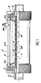
- FIG. 1 shows an acoustic filter produced in accordance with the invention.
- This filter is intended to be mounted in line on a pipe. It is used to absorb pressure waves caused for example by piston pumps or any other material. It includes, for example, a body 2 consisting of a cylinder 2a with relatively thick walls, at each end of which are mounted two attachment screws 2b. A notched nut is screwed onto each of the hooking screws. A hooking ring is mounted in a recess of each of the hooking screws. Inside the attachment rings there are fittings for connecting the filter to a pipe.
- a deformable bladder 9 made of a flexible material is mounted on each of the hooking screws 2b -
- This bladder has the shape of a cylindrical sleeve which surrounds the tube 7 and the diffuser rings 20.
- the ends of the bladder 9 are housed in a corresponding groove hooking screws 2b.
- the bladder 9 defines with the inner wall of the cylinder 2a a chamber 8 intended to receive a gas under pressure. This gas is introduced by means of a valve 8a mounted on the wall of the body 2a.
- the elastomer rings 20 prevent perforation and wear of the bladder 9 while allowing free passage of a fluid, in particular a liquid circulating in the pipe to which the acoustic filter is connected.
- a fluid in particular a liquid circulating in the pipe to which the acoustic filter is connected.
- this fluid is subjected to pulsations, for example because it is moved by a piston pump, it penetrates as shown diagrammatically by the arrows 16 in the orifices of the tube 7 and between the diffuser rings.
- the bladder then lifts up to occupy a position such as that designated by the reference 9 '.
- a knurled plug 6 is screwed onto a thread of the cylinder 2a.
- Diffuser rings 20 according to the invention are mounted on the tube 7.
- FIG. 2 a sectional view of the acoustic filter of Figure 1.
- the tube 7 is pierced with holes 13.
- the diffusers, designated by the reference 20a are constituted by a frame 21a surrounded externally by a ring 23a made of elastomer.
- Each frame 21a has a cylindrical shape of circular section. It is centered on the tube 7 of polygonal outer section. It has at one of its ends a spacer constituted, in the embodiment described, by four projections formed on the frame 21a. Of course, these spacers could also be constituted by added parts.
- FIG 3 a perspective view and partially in section of three superimposed diffusers.
- the diffuser rings 20a shown in the upper part of Figure 3 are seen in longitudinal section.
- the slots 29 formed at the end of the frame 21a In the embodiment described, there are four slots 29 which determine four passages 31 for the liquid. Of course, this number could be different depending on another embodiment. One could for example provide three slots 29 only.
- the orientation of two consecutive rings with respect to each other is indifferent.
- the lower diffuser ring 20a shown in the lower part of Figure 3 is seen from the outside. Note the passage section left free between two consecutive rings.
- the tube 7 has a polygonal outer section, for example square. This shape allows to clear four passages 33, between the faces of the square and the internal bore of the frame 21a. Four holes 13 located at 90 ° from each other are drilled in each of the faces of the square. Each orifice 13 opens into a passage 33. It is noted that the orientation of the diffuser ring 20a with respect to the square of the diffuser holder tube is indifferent. Indeed, whatever this orientation, there is a sufficient passage section for the liquid. The tube 7 also ensures the centering of the diffuser rings 20a on the tops of the square.
- the outer rings 23a ( Figures 2 and 3) have a generally cylindrical shape of circular section. They have a shallow groove 23b of rounded profile on its outer surface.
- the upper and lower faces 23c of the ring 23a form aveç the axis of the tube 7, and therefore with the axis of the diffusers, a re-entrant angle, that is to say less than 90 °. For example, this angle can be equal to 75 °.
- the faces of two successive rings 23a move closer together and leave for the fluid an outlet space which is narrower than the inlet space as can be seen in FIGS. 2 and 3. These edges thus form a kind lip.
- the rings 23a are made of a material which is compatible with that of the bladder, so that the latter does not wear out or deteriorate when it is applied to the outer periphery of the rings. They are made of the same material as the latter, namely elastomer.
- elastomer rings 23a are molded directly on the tube 7, thus constituting a tube in one piece which could also be made entirely of elastomer for low pressure applications.
- the frame 21b has a part male conical 25 connected by a round.
- the outer ring 23b has an inner cone 27 whose diameter is larger than the diameter of the male cone 25 so as to leave a space between these two cones when the rings are mounted on the tube 7.
- the spacing between two successive rings is ensured by means of slots 29 made on the terminal part of the frame. The liquid flows through the space left free between the spacers 29.
- the tube 7 causes a low pressure drop. It is unclogged. It does not filter the impurities which can be contained in the liquid, due to the large passage section offered to the fluid. It brings the fluid into the bladder 9 at reduced speed; it does not act as a filter or an oil trap; it supports without permanent deformation and without degradation of fluid / fluid back pressures greater than 250 bars; it does not cause any deterioration in the bladder when the latter is applied to the tube under the effect of a back pressure greater than 250 bars.
Landscapes
- Engineering & Computer Science (AREA)
- Physics & Mathematics (AREA)
- Fluid Mechanics (AREA)
- Mechanical Engineering (AREA)
- General Engineering & Computer Science (AREA)
- Supply Devices, Intensifiers, Converters, And Telemotors (AREA)
- Pipe Accessories (AREA)
Claims (9)
- Akustisches Filter mit einem Körper (2) mit einer Eingangsöffnung (5) und einer Ausgangsöffnung (5), einem Rohr (7), das von Öffnungen (13) durchbohrt ist, den Eingang mit dem Ausgang des körpers (2) verbindet und zur Zirkulation einer Flüssigkeit bestimmt ist, einer Base (9) aus einem weichen und verformbaren Material wobei die Blase (9) das Rohr (7) umgibt und eine äußere Kammer (8) für ein unter Druck stehendes Gas begrenzt, dadurch gekennzeichnet, daß es eine Diffusionsarordnung aufweist die Diffusionsringe (20, 20a, 20b) die auf dem Rohr (7) mit einem vorgegebenen Abstand so montiert sind, daß sie eine ringförmige Durchgangsöffnung (19) für eine Flüssigkeit zwischen zwei aufeinanderfolgenden Diffusionsringen lassen, wobei die Diffusionsanordnung gegenüber der Blase in einem weichen, dem der Blase (9) verwandten Material ausgeführt ist und Durchgangsöffnungen (19) mit einem großen Durchgangsquerschnitt verglichen mit dem der Öffnungen (13) des Rohrs besitzt.
- Filter nach Anspruch 1, dadurch gekennzeichnet, daß die Diffusionsringe (20a, 20b) so geformt sind, daß die ringförmigen Durchgangsöffnungen, die zwischen zwei aufeinanderfolgenden Ringen bestehen, geöffnet sind, wenn der im Inneren des Rohres (7) herrschende Druck gleich dem Druck außerhalb der Blase (9) ist, und geschlossen sind, wenn der Gasdruck den Druck der Flüssigkeit überschreitet
- Filter nach Anspruch 1, dadurch gekennzeichnet, daß jeder Diffusionsring (20a, 20b) sich aus einer Bewehrung (21a, 21 zusammensetzt, die außen von einem Ring (23a) aus einem Elastomer umgeben ist
- Filter nach Anspruch 3, dadurch gekennzeichnet, daß die Bewehrung (21b) einer Querschnitt eines männlichen Kegels aufweist, während der Ring aus einen Elastomer einem Teil (27) in der Form eines weiblichen Kegels mit größerem Durchmesser als der des männlichen Kegels (25) aufweist.
- Filter nach Anspruch 3, dadurch gekennzeichnet, daß Jeder Diffusionsring (20a) sich aus einer zylinderförmigen Bewehrung (21a) zusammensetzt, die außen von einem Ring aus einem Elastomer (23a) umgeben ist, der Lippen aufweist, die geeignet sind sich denen des benachbarten Diffusionsrings zu nähern, wenn ein hydraulischer Druck von außen auf die Ringe (23a) ausgeübt wird.
- Filter nach Anspruch 3, dadurch gekennzeichnet, daß es einen Kollektor (33) aufweist, der das Rohr (7) umgibt, um die Öffnungen (13) mit den Durchgangsöffnungen der Diffusionsringe in Verbindung zu bringen.
- Filter nach Anspruch 1, dadurch gekennzeichnet, daß das Rohr (7) einen äußeren, polygonalen Querschnitt aufweist, wobei eine Öffnung (13) In jede Fläche dieses Polygons auf der Höhe der Verbindung von zwei aufeinander folgenden Diffusionsringen (20) gebohrt ist.
- Filter nach Anspruch 1 dadurch gekennzeichnet, daß der Abstand zwischen zwei aufeinanderfolgenden Diffusionsringen aufgrund von Abstandsstücken (29), die am Ende der Armierung (21a, 21b) gebildet sind, aufrecht erhalten wird.
- Filter nach Anspruch 2, dadurch gekennzeichnet, daß die Ringe aus einem Elasomer (23a) Lippen aufweisen, die geeignet sind, sich denen des benachbarten Rings zu nähern, wenn ein Druck von außen auf die Ringe (23a) ausgeübt wird, und daß sie auf das Rohr (7) geformt sind.
Applications Claiming Priority (2)
| Application Number | Priority Date | Filing Date | Title |
|---|---|---|---|
| FR8312895A FR2550283B1 (fr) | 1983-08-04 | 1983-08-04 | Accumulateur hydropneumatique |
| FR8312895 | 1983-08-04 |
Related Parent Applications (2)
| Application Number | Title | Priority Date | Filing Date |
|---|---|---|---|
| EP84401586A Division EP0134738B1 (de) | 1983-08-04 | 1984-07-27 | Hydropneumatischer Speicher |
| EP84401586A Division-Into EP0134738B1 (de) | 1983-08-04 | 1984-07-27 | Hydropneumatischer Speicher |
Publications (3)
| Publication Number | Publication Date |
|---|---|
| EP0244044A2 EP0244044A2 (de) | 1987-11-04 |
| EP0244044A3 EP0244044A3 (en) | 1988-10-12 |
| EP0244044B1 true EP0244044B1 (de) | 1991-05-08 |
Family
ID=9291409
Family Applications (2)
| Application Number | Title | Priority Date | Filing Date |
|---|---|---|---|
| EP87201090A Expired - Lifetime EP0244044B1 (de) | 1983-08-04 | 1984-07-27 | Akustisches Filter |
| EP84401586A Expired EP0134738B1 (de) | 1983-08-04 | 1984-07-27 | Hydropneumatischer Speicher |
Family Applications After (1)
| Application Number | Title | Priority Date | Filing Date |
|---|---|---|---|
| EP84401586A Expired EP0134738B1 (de) | 1983-08-04 | 1984-07-27 | Hydropneumatischer Speicher |
Country Status (5)
| Country | Link |
|---|---|
| US (2) | US4638838A (de) |
| EP (2) | EP0244044B1 (de) |
| JP (1) | JPS6053201A (de) |
| DE (2) | DE3471979D1 (de) |
| FR (1) | FR2550283B1 (de) |
Families Citing this family (40)
| Publication number | Priority date | Publication date | Assignee | Title |
|---|---|---|---|---|
| US4610369A (en) * | 1985-10-07 | 1986-09-09 | Mercier Jacques H | Pressure vessel |
| JPH0645681Y2 (ja) * | 1987-04-07 | 1994-11-24 | 宣行 杉村 | ブラダ内に入子を設けたアキュムレータ |
| US4872486A (en) * | 1987-04-07 | 1989-10-10 | Nobuyuki Sugimura | Accumulator having inclined communication holes |
| US4949750A (en) * | 1988-10-28 | 1990-08-21 | Peerless Manufacturing Company | Surge reliever relief valve |
| JPH0398395U (de) * | 1990-01-26 | 1991-10-11 | ||
| IT1261305B (it) * | 1993-06-22 | 1996-05-14 | Gevipi Ag | Dispositivo smorzatore di vibrazioni e di rumore, per impianti idraulici |
| US5584512A (en) * | 1993-10-07 | 1996-12-17 | Carstensen; Kenneth J. | Tubing interconnection system with different size snap ring grooves |
| US5536028A (en) * | 1994-09-28 | 1996-07-16 | Howard; Durrell U. | Power centering compensator for vehicle steering systems |
| US6131613A (en) * | 1996-08-26 | 2000-10-17 | Aeroquip Corporation | Noise suppressor |
| ES2158581T3 (es) * | 1996-08-26 | 2001-09-01 | Eaton Aeroquip Inc | Supresor de ruido para instalaciones hidraulicas. |
| DE19747158A1 (de) * | 1997-10-24 | 1999-04-29 | Wolf Woco & Co Franz J | Pulsationsdämpfer |
| FR2772099B1 (fr) * | 1997-12-05 | 2000-02-25 | Peugeot | Sphere ou accumulateur a membrane, par exemple pour suspension hydropneumatique de vehicule automobile |
| US6483778B1 (en) | 1999-04-02 | 2002-11-19 | Raytheon Company | Systems and methods for passively compensating transducers |
| WO2001027445A2 (en) * | 1999-10-11 | 2001-04-19 | Silentor Holding A/S | A silencer |
| US6267395B1 (en) | 1999-10-18 | 2001-07-31 | Durrell U. Howard | Vehicle steering compensator with air actuated trim mechanism |
| US6860296B2 (en) * | 2001-06-27 | 2005-03-01 | Winston B. Young | High flow nozzle system for flow control in bladder surge tanks |
| US6478052B1 (en) * | 2001-07-25 | 2002-11-12 | Jeff Alan Conley | Pulsation damping assembly and method |
| US6530585B1 (en) | 2001-11-16 | 2003-03-11 | Durrell U Howard | Vehicle steering stabilizer with detent ramp in rotary plate |
| US6817620B1 (en) | 2002-08-02 | 2004-11-16 | Durrell U Howard | Precision steer wheel control system with internal solenoid |
| US7207580B2 (en) * | 2002-08-02 | 2007-04-24 | Howard Durrell U | Precision steer wheel control system with remote trim valve assembly |
| DE10241883B4 (de) * | 2002-09-10 | 2012-06-21 | Andreas Stihl Ag & Co. | Handgeführtes Arbeitsgerät mit einem Befestigungsstift für einen Abgasschalldämpfer |
| US6935460B2 (en) * | 2003-05-21 | 2005-08-30 | Airsep Corporation | Noise muffler for oxygen concentrator |
| US7278514B1 (en) * | 2003-10-17 | 2007-10-09 | The United States Of America As Represented By The Secretary Of The Navy | Acoustic noise filter |
| SE526992C2 (sv) * | 2004-03-12 | 2005-12-06 | Atlas Copco Constr Tools Ab | Hydraulisk tryckackumulator |
| US20070056649A1 (en) * | 2005-09-09 | 2007-03-15 | Chang Hsu P | Pressure container with replaceable bellows |
| US7219908B1 (en) | 2005-10-28 | 2007-05-22 | Howard Durrell U | Steer wheel control system with stationary piston and reciprocating cylinder |
| US7806419B1 (en) | 2005-10-28 | 2010-10-05 | Howard Durrell U | Steer wheel control system with reciprocating cylinder |
| US7472720B2 (en) * | 2006-10-30 | 2009-01-06 | Young Engineering & Manufacturing, Inc. | High flow nozzle system for flow control in bladder surge tanks |
| DE102007012527A1 (de) * | 2007-03-15 | 2008-09-18 | Alpha Fluid Hydrauliksysteme Müller GmbH | Diffusorbaugruppe |
| DE102008061221A1 (de) * | 2008-12-09 | 2010-06-10 | Hydac Technology Gmbh | Hydrospeicher, insbesondere Balgspeicher |
| DE102010025627A1 (de) | 2010-06-30 | 2012-01-05 | Hydac Technology Gmbh | Hydropneumatischer Blasenspeicher |
| PL2630414T3 (pl) * | 2010-10-20 | 2016-09-30 | Zespół sterowania przepływem | |
| JP5863298B2 (ja) | 2011-07-08 | 2016-02-16 | 株式会社リブドゥコーポレーション | 吸収性物品用シート部材製造装置 |
| US9352251B2 (en) * | 2014-03-12 | 2016-05-31 | Newkota Services and Rentals, LLC | Open top tank with tandem diffusers |
| DK178247B1 (en) * | 2014-03-14 | 2015-10-05 | Eyecular Technologies Aps | Inlet stratification device |
| US9683700B2 (en) * | 2014-05-20 | 2017-06-20 | Steelhead Composites, Llc. | Metallic liner pressure vessel comprising polar boss |
| JP6560098B2 (ja) * | 2015-10-27 | 2019-08-14 | 古河ロックドリル株式会社 | 油圧ダウンザホールドリルのアキュムレータ |
| FR3074541B1 (fr) * | 2017-12-01 | 2019-10-18 | Safran Aircraft Engines | Accumulateur integre a une canalisation de carburant |
| EP4242105B1 (de) * | 2022-03-11 | 2025-08-20 | Airbus Operations GmbH | Ein wasserversorgungssystem für ein flugzeug, umfassend ein puffer zum speichern von flüssigkeit unter verbraucherdruck |
| US11953154B2 (en) * | 2022-04-22 | 2024-04-09 | Amtrol Licensing Inc. | Method and system for pressure relief in a multi chamber vessel |
Family Cites Families (16)
| Publication number | Priority date | Publication date | Assignee | Title |
|---|---|---|---|---|
| FR942447A (fr) * | 1943-08-16 | 1949-02-08 | Perfectionnement aux accumulateurs d'énergie et aux appareils analogues | |
| US2760518A (en) * | 1953-11-30 | 1956-08-28 | William H Peet | Accumulator |
| US2764537A (en) * | 1954-03-31 | 1956-09-25 | Stillman Rubber Co | Composite article and method of manufacture |
| US2874721A (en) * | 1956-02-23 | 1959-02-24 | Mercier Jean | Liquid port for pressure accumulator |
| FR73894E (fr) * | 1958-07-30 | 1960-09-12 | Perfectionnements aux enceintes de fluides pouvant être mises sous pression et comportant un séparateur | |
| US3161208A (en) * | 1959-04-30 | 1964-12-15 | Mercier Jean | Pressure vessels |
| US3115162A (en) * | 1959-07-16 | 1963-12-24 | American Metal Prod | Accumulator |
| US3165166A (en) * | 1963-12-05 | 1965-01-12 | White Evans Elevator Co Inc | Silencer device for hydraulic jacks |
| FR1408181A (fr) * | 1964-01-24 | 1965-08-13 | Olaer Patent Co | Organe de guidage pour séparateur souple dans un réservoir de pression |
| US3279499A (en) * | 1964-11-06 | 1966-10-18 | Mercier Jean | Pressure vessels |
| DE1525485A1 (de) * | 1966-02-17 | 1969-08-14 | Jean Mercier | Druckbehaelter mit einer nachgiebigen Trennwand |
| FR1487445A (fr) * | 1966-05-25 | 1967-07-07 | Citroen Sa Andre | Perfectionnements apportés aux accumulateurs hydrauliques à membrane |
| FR1533447A (fr) * | 1967-06-09 | 1968-07-19 | Valve | |
| FR2110720A5 (de) * | 1970-10-28 | 1972-06-02 | Mercier J | |
| FR2149592A5 (de) * | 1971-08-13 | 1973-03-30 | Mercier J | |
| US4497388A (en) * | 1981-08-25 | 1985-02-05 | Gaulin Corporation | Pulsation dampener and acoustic attenuator |
-
1983
- 1983-08-04 FR FR8312895A patent/FR2550283B1/fr not_active Expired
-
1984
- 1984-07-24 US US06/633,920 patent/US4638838A/en not_active Expired - Fee Related
- 1984-07-27 DE DE8484401586T patent/DE3471979D1/de not_active Expired
- 1984-07-27 EP EP87201090A patent/EP0244044B1/de not_active Expired - Lifetime
- 1984-07-27 DE DE8787201090T patent/DE3484568D1/de not_active Expired - Lifetime
- 1984-07-27 EP EP84401586A patent/EP0134738B1/de not_active Expired
- 1984-08-03 JP JP59163016A patent/JPS6053201A/ja active Pending
-
1987
- 1987-05-27 US US07/056,354 patent/US4768616A/en not_active Expired - Fee Related
Also Published As
| Publication number | Publication date |
|---|---|
| US4638838A (en) | 1987-01-27 |
| EP0244044A3 (en) | 1988-10-12 |
| EP0244044A2 (de) | 1987-11-04 |
| US4768616A (en) | 1988-09-06 |
| EP0134738A2 (de) | 1985-03-20 |
| DE3484568D1 (de) | 1991-06-13 |
| FR2550283A1 (fr) | 1985-02-08 |
| EP0134738A3 (en) | 1985-07-10 |
| DE3471979D1 (en) | 1988-07-14 |
| EP0134738B1 (de) | 1988-06-08 |
| FR2550283B1 (fr) | 1988-03-18 |
| JPS6053201A (ja) | 1985-03-26 |
Similar Documents
| Publication | Publication Date | Title |
|---|---|---|
| EP0244044B1 (de) | Akustisches Filter | |
| WO2000016000A1 (fr) | Raccord etanche a geometrie variable | |
| EP0321338B1 (de) | Anzeigevorrichtung für den Membranbruch einer Membranpumpe | |
| FR2657138A1 (fr) | Partie de raccord rapide a organe de reduction de pression. | |
| EP3982014B1 (de) | Dichtungsfuge mit einer schürze | |
| FR2746167A1 (fr) | Raccord a emboitement, demontable | |
| FR2793081A1 (fr) | Dispositif d'etancheite du type presse-garniture pour un cable | |
| EP1345672B1 (de) | Dichtung für ein filterelement und modul welcher ein mit einer derartigen dichtung ausgerüstetes filterelement aufweist | |
| FR2562198A1 (fr) | Systeme d'etancheite perfectionne, convenant particulierement pour les joints a rotule des installations immergees a grande profondeur | |
| EP0574357A1 (de) | Zusammenbauvorrichtung durch Klemmen eines elastisch zusammendrückbaren Teiles | |
| EP0187608B1 (de) | Schnellverbindung für unter Druck stehende Flüssigkeitssysteme in denen der Druck 150 bar erreichen kann | |
| EP0084009B1 (de) | Rohrverbindung, insbesondere für Ölfeldröhren | |
| FR2502736A1 (fr) | Dispositif de raccordement d'un conduit de piquage sur un conduit principal | |
| CA2514502C (fr) | Dispositif de raccordement de tuyauteries | |
| EP0034101A1 (de) | Abnehmbare Verbindung, insbesondere zum Verbinden zweier Röhren oder Leitungen | |
| FR2473671A1 (fr) | Vanne a bille demontable | |
| FR2704928A3 (fr) | Elément tubiforme essentiellement flexible et déformable, en particulier pour la connexion de tubulures en général. | |
| EP0421900A1 (de) | Dichtungseinrichtung für ein zylindrisch hin- und hergehendes oder drehendes Teil in einem Raum | |
| FR3073732B1 (fr) | Adaptateur vasculaire et kit d'adaptateurs vasculaires | |
| WO2017093620A1 (fr) | Dispositif pour raccorder entre eux des tubes très haute pression | |
| CA2314770A1 (fr) | Dispositif anti-retour | |
| FR2696366A1 (fr) | Dispositif anti-extrusion pour organes d'étanchéité de sondes de sertissage hydraulique. | |
| FR2578306A1 (fr) | Raccord rapide pour circuits de fluide sous pression | |
| FR2558524A1 (fr) | Pic de taille pour mineraux et ensemble comportant ce pic | |
| FR2705574A1 (fr) | Valve de drainage implantable pour le traitement de l'hydrocéphalie. |
Legal Events
| Date | Code | Title | Description |
|---|---|---|---|
| PUAI | Public reference made under article 153(3) epc to a published international application that has entered the european phase |
Free format text: ORIGINAL CODE: 0009012 |
|
| AC | Divisional application: reference to earlier application |
Ref document number: 134738 Country of ref document: EP |
|
| AK | Designated contracting states |
Kind code of ref document: A2 Designated state(s): BE CH DE GB IT LI |
|
| PUAL | Search report despatched |
Free format text: ORIGINAL CODE: 0009013 |
|
| AK | Designated contracting states |
Kind code of ref document: A3 Designated state(s): BE CH DE GB IT LI |
|
| 17P | Request for examination filed |
Effective date: 19890316 |
|
| 17Q | First examination report despatched |
Effective date: 19900209 |
|
| GRAA | (expected) grant |
Free format text: ORIGINAL CODE: 0009210 |
|
| AC | Divisional application: reference to earlier application |
Ref document number: 134738 Country of ref document: EP |
|
| AK | Designated contracting states |
Kind code of ref document: B1 Designated state(s): BE CH DE GB IT LI |
|
| REF | Corresponds to: |
Ref document number: 3484568 Country of ref document: DE Date of ref document: 19910613 |
|
| ITF | It: translation for a ep patent filed | ||
| GBT | Gb: translation of ep patent filed (gb section 77(6)(a)/1977) | ||
| PLBE | No opposition filed within time limit |
Free format text: ORIGINAL CODE: 0009261 |
|
| STAA | Information on the status of an ep patent application or granted ep patent |
Free format text: STATUS: NO OPPOSITION FILED WITHIN TIME LIMIT |
|
| 26N | No opposition filed | ||
| PGFP | Annual fee paid to national office [announced via postgrant information from national office to epo] |
Ref country code: BE Payment date: 19940627 Year of fee payment: 11 |
|
| PGFP | Annual fee paid to national office [announced via postgrant information from national office to epo] |
Ref country code: DE Payment date: 19940701 Year of fee payment: 11 |
|
| PGFP | Annual fee paid to national office [announced via postgrant information from national office to epo] |
Ref country code: GB Payment date: 19940711 Year of fee payment: 11 |
|
| PGFP | Annual fee paid to national office [announced via postgrant information from national office to epo] |
Ref country code: CH Payment date: 19940713 Year of fee payment: 11 |
|
| PG25 | Lapsed in a contracting state [announced via postgrant information from national office to epo] |
Ref country code: GB Effective date: 19950727 |
|
| PG25 | Lapsed in a contracting state [announced via postgrant information from national office to epo] |
Ref country code: LI Effective date: 19950731 Ref country code: CH Effective date: 19950731 Ref country code: BE Effective date: 19950731 |
|
| BERE | Be: lapsed |
Owner name: COMMISSARIAT A L'ENERGIE ATOMIQUE ETABLISSEMENT D Effective date: 19950731 |
|
| REG | Reference to a national code |
Ref country code: CH Ref legal event code: PL |
|
| GBPC | Gb: european patent ceased through non-payment of renewal fee |
Effective date: 19950727 |
|
| PG25 | Lapsed in a contracting state [announced via postgrant information from national office to epo] |
Ref country code: DE Effective date: 19960402 |