EP0243795A2 - Device for guiding rounded borders through a welding zone - Google Patents
Device for guiding rounded borders through a welding zone Download PDFInfo
- Publication number
- EP0243795A2 EP0243795A2 EP87105558A EP87105558A EP0243795A2 EP 0243795 A2 EP0243795 A2 EP 0243795A2 EP 87105558 A EP87105558 A EP 87105558A EP 87105558 A EP87105558 A EP 87105558A EP 0243795 A2 EP0243795 A2 EP 0243795A2
- Authority
- EP
- European Patent Office
- Prior art keywords
- frames
- chains
- welding
- guide elements
- chain
- Prior art date
- Legal status (The legal status is an assumption and is not a legal conclusion. Google has not performed a legal analysis and makes no representation as to the accuracy of the status listed.)
- Granted
Links
Images


Classifications
-
- B—PERFORMING OPERATIONS; TRANSPORTING
- B23—MACHINE TOOLS; METAL-WORKING NOT OTHERWISE PROVIDED FOR
- B23K—SOLDERING OR UNSOLDERING; WELDING; CLADDING OR PLATING BY SOLDERING OR WELDING; CUTTING BY APPLYING HEAT LOCALLY, e.g. FLAME CUTTING; WORKING BY LASER BEAM
- B23K37/00—Auxiliary devices or processes, not specially adapted for a procedure covered by only one of the other main groups of this subclass
- B23K37/04—Auxiliary devices or processes, not specially adapted for a procedure covered by only one of the other main groups of this subclass for holding or positioning work
- B23K37/053—Auxiliary devices or processes, not specially adapted for a procedure covered by only one of the other main groups of this subclass for holding or positioning work aligning cylindrical work; Clamping devices therefor
-
- B—PERFORMING OPERATIONS; TRANSPORTING
- B23—MACHINE TOOLS; METAL-WORKING NOT OTHERWISE PROVIDED FOR
- B23K—SOLDERING OR UNSOLDERING; WELDING; CLADDING OR PLATING BY SOLDERING OR WELDING; CUTTING BY APPLYING HEAT LOCALLY, e.g. FLAME CUTTING; WORKING BY LASER BEAM
- B23K26/00—Working by laser beam, e.g. welding, cutting or boring
- B23K26/20—Bonding
- B23K26/21—Bonding by welding
- B23K26/24—Seam welding
- B23K26/244—Overlap seam welding
-
- B—PERFORMING OPERATIONS; TRANSPORTING
- B23—MACHINE TOOLS; METAL-WORKING NOT OTHERWISE PROVIDED FOR
- B23K—SOLDERING OR UNSOLDERING; WELDING; CLADDING OR PLATING BY SOLDERING OR WELDING; CUTTING BY APPLYING HEAT LOCALLY, e.g. FLAME CUTTING; WORKING BY LASER BEAM
- B23K26/00—Working by laser beam, e.g. welding, cutting or boring
- B23K26/20—Bonding
- B23K26/21—Bonding by welding
- B23K26/24—Seam welding
- B23K26/26—Seam welding of rectilinear seams
- B23K26/262—Seam welding of rectilinear seams of longitudinal seams of tubes
-
- B—PERFORMING OPERATIONS; TRANSPORTING
- B23—MACHINE TOOLS; METAL-WORKING NOT OTHERWISE PROVIDED FOR
- B23K—SOLDERING OR UNSOLDERING; WELDING; CLADDING OR PLATING BY SOLDERING OR WELDING; CUTTING BY APPLYING HEAT LOCALLY, e.g. FLAME CUTTING; WORKING BY LASER BEAM
- B23K2101/00—Articles made by soldering, welding or cutting
- B23K2101/04—Tubular or hollow articles
- B23K2101/12—Vessels
- B23K2101/125—Cans
Definitions
- the invention relates to a device for passing rounded frames through a welding zone of a machine for welding the longitudinal edges of the frames, with groups of movable guide elements which are opposite one another with respect to the frames and exert radial executives thereon.
- diabolo-like rollers are arranged as guide elements around the axis along which the frames move. Some of these rollers are supported in a radially resilient manner in such a way that they exert forces on the frames which endeavor to press their longitudinal edges against a stationary guide rail of a Z-shaped profile.
- Such guide elements which can only be moved in the radial direction and can be rotated about their own axes, serve their purpose perfectly if the frames which are passed through the welding zone have a diameter of the order of 50 mm or more, in particular if the longitudinal edges of the frames are in one Overlap squeeze seam to be welded.
- Difficulties can occur with known devices of the type described, however, if the frame diameter is less than 50 mm and / or the longitudinal edges of the frames are butt-welded together, especially by means of a laser beam. In such cases, the quality of the weld seam can be reduced by barely noticeable shocks, which occur when one of the numerous roller-shaped guide elements arranged in or near the welding zone only rolls over the front and later over the rear end of a frame.
- the invention is therefore based on the object of designing a device for passing rounded frames through a welding zone in such a way that it is also suitable for frames of small diameter of, for example, 32 or 25 mm and in particular for laser welding the longitudinal edges of such frames. Frames of such a small diameter are required above all for electrical batteries.
- the object is achieved according to the invention in a device of the type described in the introduction in that the guide elements of each group are arranged on an endless chain which has a chain strand running in the direction of movement of the frames, which on both sides contains a plane containing the welding zone and normal to the direction of movement of the frames, the welding plane, is supported by a rail.
- a transport system for can frames in resistance welding machines is known (DE-OS 28 10 188), in which two chains provided with cam-like carriers are arranged one behind the other, one chain of which passes through a station for rounding frames, in which it rotates during the rounding of the frames Frames are at least approximately stationary at times, while the second chain connects to the first chain and takes over the rounded frames from it in order to move them to the welding zone.
- the second chain ends at a distance from the welding plane; it does not guide the rounded frames, but only pushes them forward until they are gripped by two electrode rollers and conveyed by them.
- calibration tools are provided which are independent of the chains and which, like described above, act on the frames with diabolo-type rollers and do not participate in their conveying movement.
- the guide elements while they exercise the necessary radial managers on the frames, move together with them through the welding plane and are supported on both sides of the welding plane, i.e. upstream and downstream of it, on the associated rail .
- This avoids sudden impacts on the frames in the vicinity of the welding plane; the longitudinal edges of the frames consequently move smoothly and evenly through the welding zone.
- Each of the rails preferably extends continuously and in a straight line between a start and an end, the distance from the welding plane of which is greater than the length of each individual frame.
- the guide elements each have a cylindrical contact surface for the frames.
- the chains are preferably designed as roller chains and are supported by their rollers on the associated rail.
- the frames are conveyed through the welding plane in a known manner, for example by means of reciprocating drivers, or are only conveyed up to the welding plane and then moved on by electrode rollers. In such cases, it is basically possible with essentially friction-free guidance and deflection of the chains that the chains are without their own drive and are simply taken along by the frames.
- the chains each wrap around a drive wheel via which they can be driven.
- This preferred embodiment is expediently developed in that at least one of the chains, together with the associated rail and a chain tensioning wheel, can be pivoted away from the opposite chain around the associated drive wheel. In this way, the device according to the invention for maintenance and for eliminating faults can be easily opened.
- each of the rails is supported radially on two springs which are offset from one another in the conveying direction and are adjustable independently of one another.
- a slide rail leading the longitudinal edges of the frames can be arranged, in particular a rail with a Z-shaped profile, which is usually referred to as a Z-rail. It is advantageous if, according to a further feature of the invention, the slide rail is arranged diametrically opposite a magnetic rail additionally guiding the frames.
- a guide sleeve is arranged upstream of the chains, which tapers in a funnel shape in the direction of movement of the frames and minimizes least has an axial slot, along which a pawl for inserting the frames between the chains is movable.
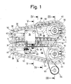
- the device shown has the task of cylindrically rounded frames 10, which consist, for example, of uncoated steel sheet or tinplate, in such a way that their longitudinal edges 12 and 14 can be welded tightly to one another, while the frames 10 along their axis A forward, in Fig. 1 and 2 from left to right, through a normal to the axis A welding plane B.
- Such welded housings are provided in particular as housings for electric batteries.
- the frames 10 were rolled around a stationary lower arm 16 by a round device of conventional design, which extends parallel to the usual horizontal axis A through a likewise stationary guide sleeve 18 and is centered in the illustrated one Device protrudes.
- a round device of conventional design which extends parallel to the usual horizontal axis A through a likewise stationary guide sleeve 18 and is centered in the illustrated one Device protrudes.
- Fixed slide rail 20 of Z-shaped profile, on which the longitudinal edges 14 and 16 of the frames are guided.
- the slide rail 20 ends shortly before the welding plane B, in which a laser cannon 22 is arranged, the beam 24 of which is indicated in FIG. 4.
- the longitudinal edges 12 and 14 run between a front end section 26 of the lower arm 16 and a slide shoe 28 arranged above it, both of which are perforated in such a way that they do not obstruct the beam 24.
- a cooled absorber 30 is arranged vertically below it.
- a pawl 32 is provided which can be moved back and forth parallel to the axis A by means of a conventional drive device, not shown, for example of the type of a crank drive, and each time it moves forward through an axial slot 34 the guide sleeve 18 protrudes into the interior.
- a conventional drive device not shown, for example of the type of a crank drive
- Each frame 10 which emerges from the guide sleeve 18 is gripped by two groups of guide elements 36 which are each arranged on an endless chain 38.
- the two chains 38 are arranged symmetrically with respect to the axis A, each have a chain strand running parallel to it and extend in a horizontal plane around a drive wheel 40 and a chain tensioning wheel 42.
- a chain tensioning wheel 42 Of the chain tensioning wheels 42 from the chains 38 converge towards their axially parallel chain strands.
- both chains 38 are designed as triple roller chains; their members are connected to each other by hinge bolts 44, on which three rollers 46 are mounted.
- Each of the guide elements 36 is fastened to two adjacent hinge pins 44 and has a cylindrical contact surface 48, the diameter of which corresponds to the outer diameter of the frames 10.
- Each of the frames 10 is gripped by three guide elements 36 on both sides of the frame length shown and is guided along the axis A through the welding plane B.
- a driver 50 is attached to the last of the three guide elements 36.
- the drivers 50 on the two axially parallel chain strands face each other in pairs, so that each frame 10 is grasped by a pair of drivers 50, which lies against its rear end, and is therefore reliably moved through the welding plane B when the radial forces are present which the guide elements 36 act on the frames 10 via their contact surfaces 48 should be too weak to generate sufficient frictional forces to take the frames with them.
- the magnitude of the radial forces mentioned is determined in that the straight chain strand of each of the two chains 38 is supported on a rail 52.
- Each of the rails 52 has three guide ribs 54 arranged one above the other parallel to the axis A, on which the rollers 46 of the associated chain 38 run.
- the length of the guide ribs 54 in front of and behind the welding plane B is greater than the frame length; as a result, each frame 10 is guided via the guide elements 36 accompanying it from a point in time before the front end of the frame reaches the welding plane B to a point in time after its rear end has left the welding plane.
- Each of the two rails 52 is slidably guided between two sliding plates 56, each of which is attached to a cheek 58.
- two threaded bolts 60 are screwed, which extend in a horizontal plane radially to the axis A and are guided in a support 62 which is fastened between the two associated cheeks 58.
- two compression springs 64 are clamped, which are arranged around each of the threaded bolts 60 and the rail with a supporting force of the order of magnitude, for example Support 25 to 30 kg. In this way, the axially parallel chain strand of each of the two chains 38 is adjustably supported by the associated rail 52 in a radial direction with respect to the axis A.
- a further support 66 is fastened to the associated cheeks 58, on which the associated chain tensioning wheel 42 is displaceably guided and is also supported by a compression spring 68.
- the two drive wheels 40 are each attached to a vertical shaft 70, which is mounted in a sleeve 72.
- the two sleeves 72 are fastened to a common, fixed base plate 74.
- the two pairs of cheeks 58 belonging together are each mounted on one of the two shafts 70, so that they can be pivoted away from one another into a maintenance position about the associated shaft from their operating position shown in FIGS. 1 to 5.
- a pair of cheeks 58 including associated device parts in particular chain 38 including guide elements 36 and chain tensioning wheel 42, is pivoted into the maintenance position, while the other pair of cheeks 58 including associated device parts are still in their operating position.
- a lock plate 76 is fastened to the upper cheek 58 of one of the two cheek pairs, on which a tie rod 78 is pivotably mounted.
- a lock plate 80 is fastened in a corresponding manner to the upper cheek 58 of the other cheek pair, which can be clamped together with the lock plate 76 in the operating position of the device by means of the tie rod 78 and a screw handle 82 screwed onto it.
- the distance between the axially parallel chain strands of the two chains 38 in the operating position is determined by an adjustable stop screw 84 which is screwed into the lock plate 80 and abuts the lock plate 76 with one of its end faces.
- the two shafts 70 can be driven in opposite directions at exactly the same speed;
- a controllable electric motor 86 is connected via a toothed pinion 88 and a toothed belt 90 to two toothed wheels 92, which are each attached to one of the shafts 70.
- the toothed belt 90 additionally wraps around a deflection wheel 94 which is mounted on the base plate 94.
- the drawings show how four frames 10 pass through the device described in the foregoing at fixed intervals and are guided by the guide elements 36 on the axially parallel chain strands.
- the longitudinal edges 12 and 14 are welded together by the beam 24.
- the welded frames 10 are then conveyed further between the axially parallel chain strands and finally delivered at a relatively large distance from the welding plane B, for example to a further processing device.
- a magnetic rail 96 is fastened on supports 98 below the slide rail 20.
- the frames 10 slide in a region diametrically opposite their longitudinal edges 12 and 14 on the magnetic rail 96 before and while they are gripped by the guide elements 36. This ensures that the frames 10 assume exactly a predetermined position with respect to the guide elements 36.
- the magnet strength is chosen so that the frictional force between each frame 10 and the magnetic rail 96 corresponds at least approximately to the sum of the frictional forces between the longitudinal edges 12 and 14 and the slide rail 20. As a result, the moments of these frictional forces are at least approximately in equilibrium and can therefore not tilt the frame 10.
Landscapes
- Physics & Mathematics (AREA)
- Optics & Photonics (AREA)
- Engineering & Computer Science (AREA)
- Mechanical Engineering (AREA)
- Plasma & Fusion (AREA)
- Advancing Webs (AREA)
- Laser Beam Processing (AREA)
Abstract
An einer Maschine zum Verschweißen der Längsränder (12,14) gerundeter Zargen (10) sind zwei Gruppen von beweglichen Führungselementen (36) einander in bezug auf die Zargen gegenüberliegend angeordnet, die auf die Zargen (10) radiale Führungskräfte ausüben. Die Führungselemente (36) jeder der beiden Gruppen sind an einer endlosen Kette (38) befestigt. Jede dieser Ketten (38) hat einen in Bewegungsrichtung (Achse A) der Zargen (10) verlaufenden Kettenstrang, der beiderseits einer die Schweißzone enthaltenden, zur Bewegungsrichtung der Zargen (10) normalen Schweißebene (B) durch eine Schiene (52) abgestützt ist. Die Führungselemente (36) bewegen sich mit den Zargen (10) durch die Schweißebene (B) hindurch. Dadurch werden stoßartige Einwirkungen auf die Zargen (10) in der Nähe der Schweißebene (B) vermieden; die Längsränder (12, 14) können infolgedessen besonders gleichmäßig miteinander verschweißt werden, insbesondere mittels eines Laserstrahls. On a machine for welding the longitudinal edges (12, 14) of rounded frames (10), two groups of movable guide elements (36) are arranged opposite one another with respect to the frames, which exert radial managers on the frames (10). The guide elements (36) of each of the two groups are attached to an endless chain (38). Each of these chains (38) has a chain strand running in the direction of movement (axis A) of the frames (10), which is supported on both sides of a welding plane (B) which contains the welding zone and is normal to the direction of movement of the frames (10) by a rail (52). The guide elements (36) move with the frames (10) through the welding plane (B). This avoids impact-like effects on the frames (10) in the vicinity of the welding plane (B); the longitudinal edges (12, 14) can consequently be welded to one another in a particularly uniform manner, in particular by means of a laser beam.
Description
Die Erfindung betrifft eine Vorrichtung zum Hindurchführen gerundeter Zargen durch eine Schweißzone einer Maschine zum Verschweißen der Längsränder der Zargen, mit Gruppen von beweglichen Führungselementen, die einander in bezug auf die Zargen gegenüberliegen und auf diese radiale Führungskräfte ausüben.The invention relates to a device for passing rounded frames through a welding zone of a machine for welding the longitudinal edges of the frames, with groups of movable guide elements which are opposite one another with respect to the frames and exert radial executives thereon.
Bei bekannten Vorrichtungen dieser Gattung (DE-PS 25 59 671) sind als Führungselemente diaboloartige Rollen rings um die Achse, längs derer sich die Zargen bewegen, angeordnet. Ein Teil dieser Rollen ist derart radial federnd abgestützt, daß sie auf die Zargen Kräfte ausüben, die bestrebt sind, deren Längsränder gegen eine ortsfeste Führungsschine von Z-förmigem Profil zu drücken. Solche nur in radialer Richtung bewegliche und um je eine eigene Achse drehbare Führungselemente erfüllen ihren Zweck einwandfrei, wenn die Zargen, die durch die Schweißzone hindurchgeführt werden, einen Durchmesser in der Größenordnung von 50 mm oder mehr haben, insbesondere wenn die Längsränder der Zargen in einer Überlappt-Quetschnaht verschweißt werden. Schwierigkeiten können mit bekannten Vorrichtungen der beschriebenen Gattung jedoch dann auftreten, wenn der Zargendurchmesser kleiner als 50 mm ist und/oder die Längsränder der Zargen miteinander stumpf verschweißt werden, insbesondere mittels Laserstrahl. In solchen Fällen kann die Qualität der Schweißnaht durch kaum merkliche Stöße vermindert werden, die jeweils dann auftreten, wenn eines der zahlreichen in oder nahe der Schweißzone angeordneten rollenförmigen Führungselemente erst über das vordere und später über das hintere Ende einer Zarge rollt.In known devices of this type (DE-PS 25 59 671) diabolo-like rollers are arranged as guide elements around the axis along which the frames move. Some of these rollers are supported in a radially resilient manner in such a way that they exert forces on the frames which endeavor to press their longitudinal edges against a stationary guide rail of a Z-shaped profile. Such guide elements, which can only be moved in the radial direction and can be rotated about their own axes, serve their purpose perfectly if the frames which are passed through the welding zone have a diameter of the order of 50 mm or more, in particular if the longitudinal edges of the frames are in one Overlap squeeze seam to be welded. Difficulties can occur with known devices of the type described, however, if the frame diameter is less than 50 mm and / or the longitudinal edges of the frames are butt-welded together, especially by means of a laser beam. In such cases, the quality of the weld seam can be reduced by barely noticeable shocks, which occur when one of the numerous roller-shaped guide elements arranged in or near the welding zone only rolls over the front and later over the rear end of a frame.
Der Erfindung liegt deshalb die Aufgabe zugrunde, eine Vorrichtung zum Hindurchführen gerundeter Zargen durch eine Schweißzone derart zu gestalten, daß sie sich auch für Zargen kleinen Durchmessers von beispielsweise 32 oder 25 mm und insbesondere zum Laserschweißen der Längsränder solcher Zargen eignet. Zargen derart kleinen Durchmessers sind vor allem für elekrische Batterien erforderlich.The invention is therefore based on the object of designing a device for passing rounded frames through a welding zone in such a way that it is also suitable for frames of small diameter of, for example, 32 or 25 mm and in particular for laser welding the longitudinal edges of such frames. Frames of such a small diameter are required above all for electrical batteries.
Die Aufgabe ist bei einer Vorrichtung der eingangs beschriebenen Gattung erfindungsgemäß dadurch gelöst, daß die Führungselemente jeder Gruppe an einer endlosen Kette angeordnet sind, die einen in Bewegungsrichtung der Zargen verlaufenden Kettenstrang aufweist, der beiderseits einer die Schweißzone enthaltenden, zur Bewegungsrichtung der Zargen normalen Ebene, der Schweißebene, durch eine Schiene abgestützt ist.The object is achieved according to the invention in a device of the type described in the introduction in that the guide elements of each group are arranged on an endless chain which has a chain strand running in the direction of movement of the frames, which on both sides contains a plane containing the welding zone and normal to the direction of movement of the frames, the welding plane, is supported by a rail.
Es ist zwar eine Transportanlage für Dosenzargen in Widerstandsschweißmaschinen bekannt (DE-OS 28 10 188), bei der zwei mit nockenartigen Mitnehmern versehende Ketten hintereinander angeordnet sind, von denen eine Kette eine Station zum Runden von Zargen durchläuft, in welcher sie während des Rundens der Zargen zeitweise mindestens annähernd stillsteht, während die zweite Kette sich an die erste Kette anschließt und von dieser die gerundeten Zargen übernimmt, um sie zur Schweißzone zu verschieben. Die zweite Kette endet jedoch in einem Abstand vor der Schweißebene; sie führt die gerundeten Zargen nicht, sondern schiebt sie nur vorwärts, bis sie von zwei Elektrodenrollen erfaßt und von diesen weitergefördert werden. Zum Hindurchführen der Zargen durch die Schweißebene sind von den Ketten unabhängige Kalibrierwerkzeuge vorgesehen, die, wie oben beschrieben, mit diaboloartigen Rollen auf die Zargen einwirken und an deren Förderbewegung nicht teilnehmen.A transport system for can frames in resistance welding machines is known (DE-OS 28 10 188), in which two chains provided with cam-like carriers are arranged one behind the other, one chain of which passes through a station for rounding frames, in which it rotates during the rounding of the frames Frames are at least approximately stationary at times, while the second chain connects to the first chain and takes over the rounded frames from it in order to move them to the welding zone. However, the second chain ends at a distance from the welding plane; it does not guide the rounded frames, but only pushes them forward until they are gripped by two electrode rollers and conveyed by them. For passing the frames through the welding plane, calibration tools are provided which are independent of the chains and which, like described above, act on the frames with diabolo-type rollers and do not participate in their conveying movement.
Demgegenüber wird mit der Erfindung erreicht, daß die Führungselemente, während sie die erforderlichen radialen Führungskräfte auf die Zargen ausüben, sich mit diesen gemeinsam durch die Schweißebene hindurch bewegen und dabei beiderseits der Schweißebene, also förderstromaufwärts und förderstromabwärts von ihr, an der zugehörigen Schiene abgestützt sind. Dadurch werden stoßartige Einwirkungen auf die Zargen in der Nähe der Schweißebene vermieden; die Längsränder der Zargen bewegen sich infolgedessen ruhig und gleichmäßig durch die Schweißzone hindurch.In contrast, it is achieved with the invention that the guide elements, while they exercise the necessary radial managers on the frames, move together with them through the welding plane and are supported on both sides of the welding plane, i.e. upstream and downstream of it, on the associated rail . This avoids sudden impacts on the frames in the vicinity of the welding plane; the longitudinal edges of the frames consequently move smoothly and evenly through the welding zone.
Vorzugsweise erstreckt sich jede der Schienen ununterbrochen und geradlinig zwischen einem Anfang und einem Ende, deren Abstand von der Schweißebene größer ist als die Länge jeder einzelnen Zarge.Each of the rails preferably extends continuously and in a straight line between a start and an end, the distance from the welding plane of which is greater than the length of each individual frame.
Es ist ferner vorteilhaft, wenn die Führungselemente an je zwei Gelenkbolzen der zugehörigen Kette befestigt sind.It is also advantageous if the guide elements are attached to two hinge pins of the associated chain.
Außerdem ist es zweckmäßig, wenn die Führungselemente je eine zylindrische Anlagefläche für die Zargen haben.It is also useful if the guide elements each have a cylindrical contact surface for the frames.
Die Ketten sind vorzugsweise als Rollenketten ausgebildet und über ihre Rollen an der zugehörigen Schiene abgestützt.The chains are preferably designed as roller chains and are supported by their rollers on the associated rail.
Es ist denkbar, daß die Zargen in bekannter Weise, z.B. mittels hin- und hergehender Mitnehmer, durch die Schweißebene hindurchgefördert werden oder nur bis zur Schweißebene gefördert und dann von Elektrodenrollen weiterbewegt werden. In solchen Fällen ist es bei im wesentlichen reibungsfreier Führung und Umlenkung der Ketten grundsätzlich möglich, daß die Ketten ohne eigenen Antrieb sind und von den Zargen einfach mitgenommen werden.It is conceivable that the frames are conveyed through the welding plane in a known manner, for example by means of reciprocating drivers, or are only conveyed up to the welding plane and then moved on by electrode rollers. In such cases, it is basically possible with essentially friction-free guidance and deflection of the chains that the chains are without their own drive and are simply taken along by the frames.
Bei einer bevorzugten Ausführungsform der Erfindung umschlingen die Ketten jedoch je ein Antriebsrad, über das sie antreibbar sind.In a preferred embodiment of the invention, however, the chains each wrap around a drive wheel via which they can be driven.
Diese bevorzugte Ausführungsform ist zweckmäßigerweise dadurch weitergebildet, daß wenigstens eine der Ketten zusammen mit der zugehörigen Schiene und einem Kettenspannrad um das zugehörige Antriebsrad herum von der gegenüberliegenden Kette wegschwenkbar ist. Auf diese Weise läßt sich die erfindungsgemässe Vorrichtung zur Wartung und zur Beseitigung von Störungen leicht öffnen.This preferred embodiment is expediently developed in that at least one of the chains, together with the associated rail and a chain tensioning wheel, can be pivoted away from the opposite chain around the associated drive wheel. In this way, the device according to the invention for maintenance and for eliminating faults can be easily opened.
Es ist ferner vorteilhaft, wenn jede der Schienen an zwei Federn radial abgestützt ist, die in Förderrichtung gegeneinander versetzt und unabhängig voneinander einstellbar sind. Mit dieser Einstellmöglichkeit läßt sich auf besonders ein fache Weise erreichen, daß die Längsränder der Zargen in der Schweißzone eine genau vorbestimmte Lage in bezug zueinander haben, sich also entweder um einen bestimmten Betrag überlappen, wenn eine Überlappt-Schweißnaht hergestellt werden soll oder die Längsränder stumpf aneinanderliegen, wenn, insbesondere mit einem Laserstrahl, eine Stumpfschweißnaht gebildet werden soll.It is also advantageous if each of the rails is supported radially on two springs which are offset from one another in the conveying direction and are adjustable independently of one another. With this setting option it can be achieved in a particularly simple way that the longitudinal edges of the frames in the welding zone have a precisely predetermined position in relation to one another, that is to say they either overlap by a certain amount if an overlapping weld seam is to be produced or the longitudinal edges are blunt abut each other if, especially with a laser beam, a butt weld is to be formed.
In einer Längsmittelebene der erfindungsgemäßen Vorrichtung kann, wie üblich, eine die Längsränder der Zargen führende Gleitschiene angeordnet sein, insbesondere eine Schiene mit Z-förmigem Profil, die üblicherweise als Z-Schiene bezeichnet wird. Dabei ist es vorteilhaft, wenn gemäß einem weiteren Merkmal der Erfindung der Gleitschiene diametral gegenüber eine die Zargen zusätzlich führende Magnetschiene angeordnet ist.In a longitudinal center plane of the device according to the invention, as is customary, a slide rail leading the longitudinal edges of the frames can be arranged, in particular a rail with a Z-shaped profile, which is usually referred to as a Z-rail. It is advantageous if, according to a further feature of the invention, the slide rail is arranged diametrically opposite a magnetic rail additionally guiding the frames.
Schließlich ist es vorteilhaft, wenn förderstromaufwärts von den Ketten eine Führungshülse angeordnet ist, die sich in Bewegungsrichtung der Zargen trichterförmig verjüngt und minde stens einen axialen Schlitz aufweist, längs dessen eine Klinke zum Einschieben der Zargen zwischen die Ketten bewegbar ist.Finally, it is advantageous if a guide sleeve is arranged upstream of the chains, which tapers in a funnel shape in the direction of movement of the frames and minimizes least has an axial slot, along which a pawl for inserting the frames between the chains is movable.
Ein Ausführungsbeispiel der Erfindung wird im folgenden anhand schematischer Zeichnungen mit weiteren Einzelheiten erläutert. Es zeigt:
- Fig. 1 eine erfindungsgemäße Vorrichtung in Draufsicht,
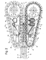
- Fig. 2 diesselbe Vorrichtung in teilweise demontiertem Zustand und teilweise in einem waagerechten Schnitt,
- Fig. 3 den Schnitt in der senkrechten Ebene III-III in Fig. 1,
- Fig. 4 den Schnitt in der senkrechten Ebene IV-IV in Fig. 1,
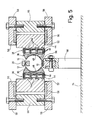
- Fig. 5 den Schnitt in der senkrechten Ebene V-V in Fig. 1 und
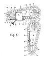
- Fig. 6 die Vorrichtung in einer der Fig. 1 entsprechenden Draufsicht, jedoch in geöffnetem Zustand.
- 1 shows a device according to the invention in plan view,
- 2 the same device in a partially disassembled state and partially in a horizontal section,
- 3 shows the section in the vertical plane III-III in FIG. 1,
- 4 shows the section in the vertical plane IV-IV in FIG. 1,
- Fig. 5 shows the section in the vertical plane VV in Fig. 1 and
- Fig. 6 shows the device in a plan view corresponding to FIG. 1, but in the open state.
Die dargestellte Vorrichtung hat die Aufgabe, zylindrisch um eine Achse A gerundete Zargen 10, die beispielsweise aus unbeschichtetem Stahlblech oder aus Weißblech bestehen, derart zu führen, daß ihre Längsränder 12 und 14 fest aneinanderliegend miteinander verschweißt werden können, während die Zargen 10 längs ihrer Achse A vorwärts, in Fig. 1 und 2 von links nach rechts, durch eine zur Achse A normale Schweißebene B hindurchbewegt werden. Solche geschweißten Gehäuse sind insbesondere als Gehäuse für elektrische Batterien vorgesehen.The device shown has the task of cylindrically
Die Zargen 10 sind, ehe sie die dargestellte Vorrichtung erreichen, von einer Rundvorrichtung üblicher Bauart um einen ortsfesten unteren Arm 16 herum gerollt worden, der sich parallel zu der in üblicher Weise waagerechten Achse A durch eine ebenfalls ortsfeste Führungshülse 18 hindurcherstreckt und mittig in die dargestellte Vorrichtung hineinragt. In Förderrichtung der Zargen 10 stromabwärts von der Führungshülse 18 ist auf dem unteren Arm 16 eine ebenfalls übliche Gleitschiene 20 von Z-förmigem Profil befestigt, an der die Längsränder 14 und 16 der Zargen geführt sind. Die Gleitschiene 20 endet kurz vor der Schweißebene B, in der eine Laserkanone 22 angeordnet ist, deren Strahl 24 in Fig. 4 angedeutet ist. Im Bereich des Strahls 24 laufen die Längsränder 12 und 14 zwischen einem vorderen Endabschnitt 26 des unteren Arms 16 und einem über diesem angeordneten Gleitschuh 28 hindurch, die beide derart gelocht sind, daß sie den Strahl 24 nicht behindern. Senkrecht darunter ist ein gekühlter Absorber 30 angeordnet.Before reaching the device shown, the
Zum Hindurchschieben der Zargen 10 durch die Führungshülse 18 ist eine Klinke 32 vorgesehen, die mittels einer nicht dargestellten, üblichen Antriebsvorrichtung, beispielsweise von der Art eines Kurbeltriebs, parallel zur Achse A hin- und herbewegbar ist und jeweils bei ihrer Vorwärtsbewegung durch einen axialen Schlitz 34 der Führungshülse 18 in deren Innenraum hineinragt. Jede Zarge 10, die aus der Führungshülse 18 austritt, wird von zwei Gruppen von Führungselementen 36 erfaßt, die an je einer endlosen Kette 38 angeordnet sind.To push the
Die beiden Ketten 38 sind in der Betriebsstellung der Vorrichtung in bezug auf die Achse A symmetrisch angeordnet, haben je einen zu dieser parallelen, vorwärtslaufenden Kettenstrang und erstrecken sich in einer waagerechten Ebene um je ein Antriebsrad 40 und je ein Kettenspannrad 42. Von den Kettenspannrädern 42 aus konvergieren die Ketten 38 zu ihren achsparallelen Kettensträngen hin.In the operating position of the device, the two
Im dargestellten Beispiel sind beide Ketten 38 als Dreifachrollenketten ausgebildet; ihre Glieder sind miteinander durch Gelenkbolzen 44 verbunden, auf denen je drei Rollen 46 gelagert sind. Jedes der Führungselemente 36 ist an zwei benachbarten Gelenkbolzen 44 befestigt und hat eine zylindrische Anlagefläche 48, deren Durchmesser mit dem Außendurchmesser der Zargen 10 übereinstimmt.In the example shown, both
Jede der Zargen 10 wird bei der dargestellten Zargenlänge an ihren beiden Seiten von je drei Führungselementen 36 erfaßt und längs der Achse A durch die Schweißebene B hindurchgeführt. Am letzten der je drei Führungselemente 36 ist ein Mitnehmer 50 befestigt. Die Mitnehmer 50 an den beiden achsparallelen Kettensträngen stehen einander paarweise gegenüber, sodaß jede Zarge 10 von einem Paar Mitnehmer 50, das sich an ihr hinteres Ende anlegt, erfaßt und somit auch dann zuverlässig durch die Schweißebene B hindurchbewegt wird, wenn die radialen Kräfte, mit denen die Führungselemente 36 über ihre Anlageflächen 48 auf die Zargen 10 einwirken, zu schwach sein sollten, um zum Mitnehmen der Zargen ausreichende Reibungskräfte zu erzeugen.Each of the
Die Größe der genannten radialen Kräfte wird dadurch bestimmt, daß der gerade Kettenstrang jeder der beiden Ketten 38 an einer Schiene 52 abgestützt ist. Jede der Schienen 52 hat drei parallel zur Achse A übereinander angeordnete Führungsrippen 54, auf denen die Rollen 46 der zugehörigen Kette 38 laufen. Die Länge der Führungsrippen 54 vor und hinter der Schweißebene B ist größer als die Zargenlänge; infolgedessen ist jede Zarge 10 über die sie begleitenden Führungselemente 36 von einem Zeitpunkt, ehe das vordere Ende der Zarge die Schweißebene B erreicht, bis zu einem Zeitpunkt, nach dem ihr hinteres Ende die Schweißebene verlassen hat, erschütterungsfrei geführt.The magnitude of the radial forces mentioned is determined in that the straight chain strand of each of the two
Jede der beiden Schienen 52 ist verschiebbar zwischen zwei Gleitplatten 56 geführt, die an je einer Wange 58 befestigt sind. In jede der Schienen 52 sind zwei Gewindebolzen 60 eingeschraubt, die sich in einer waagerechten Ebene radial zur Achse A erstrecken und in einer Stütze 62 geführt sind, die zwischen den beiden zugehörigen Wangen 58 befestigt ist. Zwischen jeder der beiden Schienen 52 und der zugehörigen Stütze 62 sind zwei Druckfedern 64 eingespannt, die rings um je einen der Gewindebolzen 60 angeordnet sind und die Schiene mit einer Stützkraft in der Größenordnung von beispielsweise 25 bis 30 kg abstützen. Auf diese Weise ist der achsparallele Kettenstrang jeder der beiden Ketten 38 durch die zugehörige Schiene 52 in einer bezüglich der Achse A radialen Richtung einstellbar abgestützt.Each of the two
In der Nachbarschaft der Schienen 52 ist an den jeweils zugehörigen Wangen 58 eine weitere Stütze 66 befestigt, an der das zugehörige Kettenspannrad 42 verschiebbar geführt und ebenfalls über eine Druckfeder 68 abgestützt ist.In the vicinity of the
Die beiden Antriebsräder 40 sind an je einer senkrechten Welle 70 befestigt, die in je einer Büchse 72 gelagert ist. Die beiden Büchsen 72 sind an einer gemeinsamen, ortsfesten Grundplatte 74 befestigt. Die beiden Paare zusammengehöriger Wangen 58 sind auf je einer der beiden Wellen 70 gelagert, sodaß sie sich um die zugehörige Welle aus ihrer in Fig. 1 bis 5 abgebildeten Betriebsstellung voneinander weg in eine Wartungsstellung schwenken lassen.The two
In Fig. 6 ist ein Paar Wangen 58 samt zugehörigen Vorrichtungsteilen, insbesondere Kette 38 samt Führungselementen 36 und Kettenspannrad 42, in die Wartungsstellung geschwenkt, während das andere Paar Wangen 58 samt zugehörigen Vorrichtungsteilen noch seine Betriebsstellung einnimmt. An der oberen Wange 58 eines der beiden Wangenpaare ist eine Schloßplatte 76 befestigt, an der ein Zuganker 78 schwenkbar gelagert ist. An der oberen Wange 58 des anderen Wangenpaars ist in entsprechender Weise eine Schloßplatte 80 befestigt, die sich in der Betriebsstellung der Vorrichtung mittels des Zugankers 78 und eines auf diesen aufgeschraubten Schraubgriffs 82 mit der Schloßplatte 76 zusammenspannen läßt. Der Abstand, den die achsparallelen Kettenstränge der beiden Ketten 38 in der Betriebsstellung voneinander einhalten, wird durch eine einstellbare Anschlagschraube 84 bestimmt, die in die Schloßplatte 80 eingeschraubt ist und mit einer ihrer Stirnflächen gegen die Schloßplatte 76 stößt.In Fig. 6, a pair of
Die beiden Wellen 70 sind gegensinnig mit genau gleicher Geschwindigkeit antreibbar; zu diesem Zweck ist ein regelbarer Elektromotor 86 über ein Zahnritzel 88 und einen Zahnriemen 90 mit zwei Zahnrädern 92 verbunden, die auf je einer der Wellen 70 befestigt sind. Der Zahnriemen 90 umschlingt zusätzlich ein Umlenkrad 94, das an der Grundplatte 94 gelagert ist.The two
In den Zeichnungen ist dargestellt, wie vier Zargen 10 in festgelegten Abständen hintereinander die im vorstehenden bechriebene Vorrichtung durchlaufen und dabei von den Führungselementen 36 an den achsparallelen Kettensträngen geführt sind. In der Schweißzone werden die Längsränder 12 und 14 durch den Strahl 24 miteinander verschweißt. Die fertiggeschweißten Zargen 10 werden danach zwischen den achsparallelen Kettensträngen weitergefördert und schließlich in einem verhältnismäßig großen Abstand von der Schweißebene B abgegeben, beispielsweise an eine weiterverarbeitende Vorrichtung.The drawings show how four
Um die Führung der Zargen 10 noch weiter zu verbessern, ist unterhalb der Gleitschiene 20 eine Magnetschiene 96 auf Stützen 98 befestigt. Die Zargen 10 gleiten in einem ihren Längsrändern 12 und 14 diametral gegenüberliegenden Bereich auf der Magnetschiene 96, ehe und während sie von den Führungselementen 36 erfaßt werden. Dadurch wird sichergestellt, daß die Zargen 10 genau eine vorbestimmte Lage in bezug auf die Führungselemente 36 einnehmen. Die Magnetstärke ist so gewählt, daß die Reibungskraft zwischen jeder Zarge 10 und der Magnetschiene 96 mit der Summe der Reibungskräfte zwischen den Längsrändern 12 und 14 und der Gleitschiene 20 mindestens ungefähr übereinstimmt. Dadurch stehen die Momente dieser Reibungskräfte wenigstens anähernd im Gleichgewicht und können die Zarge 10 deshalb nicht verkanten.In order to further improve the guidance of the
Claims (10)
dadurch gekennzeichnet, daß jede der Schienen (52) sich ununterbrochen und geradlinig zwischen einem Anfang und einem Ende erstreckt, deren Abstand von der Schweißebene B größer ist als die Länge jeder einzelnen Zarge (10).2. Device according to claim 1,
characterized in that each of the rails (52) extends continuously and in a straight line between a start and an end, the distance from the welding plane B of which is greater than the length of each individual frame (10).
dadurch gekennzeichnet, daß die Führungselemente (36) an je zwei Gelenkbolzen (44) der zugehörigen Kette (38) befestigt sind.3. Device according to claim 1 or 2,
characterized in that the guide elements (36) are each attached to two hinge pins (44) of the associated chain (38).
dadurch gekennzeichnet, daß die Führungselemente (36) je eine zylindrische Anlagefläche (48) für die Zargen (10) haben.4. Device according to one of claims 1 to 3,
characterized in that the guide elements (36) each have a cylindrical contact surface (48) for the frames (10).
dadurch gekennzeichnet, daß die Ketten (38) als Rollenketten ausgebildet und über ihre Rollen (46) an der zugehörigen Schiene (52) abgestützt sind.5. Device according to one of claims 1 to 4,
characterized in that the chains (38) are designed as roller chains and are supported by their rollers (46) on the associated rail (52).
dadurch gekennzeichnet, daß die Ketten (38) je ein Antriebsrad (40) umschlingen, über das sie antreibbar sind.6. Device according to one of claims 1 to 5,
characterized in that the chains (38) each wrap around a drive wheel (40) via which they can be driven.
dadurch gekennzeichnet, daß wenigstens eine der Ketten (38) zusammen mit der zugehörigen Schiene (52) und einem Kettenspannrad (42) um das zugehörige Antriebsrad (40) herum von der gegenüberliegenden Kette (38) wegschwenkbar ist.7. The device according to claim 6,
characterized in that at least one of the chains (38) together with the associated rail (52) and a chain tensioning wheel (42) can be pivoted away from the opposite chain (38) around the associated drive wheel (40).
dadurch gekennzeichnet, daß jede der Schienen (52) an zwei Federn (64) radial abgestützt ist, die in Bewegungsrichtung der Zargen (10) gegeneinander versetzt und unabhängig voneinander einstellbar sind.8. Device according to one of claims 1 to 7,
characterized in that each of the rails (52) is supported radially on two springs (64) which are offset from one another in the direction of movement of the frames (10) and are adjustable independently of one another.
dadurch gekennzeichnet, daß der Gleitschiene (20) diametral gegenüber eine die Zargen (10) zusätzlich führende Magnetschiene (96) angeordnet ist.9. Device according to one of claims 1 to 8 with one of the longitudinal edges (12, 14) of the frames (10) leading slide rail (20),
characterized in that the slide rail (20) is arranged diametrically opposite a magnetic rail (96) additionally guiding the frames (10).
dadurch gekennzeichnet, daß förderstromaufwärts von den Ketten (38) eine Führungshülse (18) angeordnet ist, die sich in Bewegungsrichtung der Zargen (10) trichterförmig verengt und mindestens einen axialen Schlitz (34) aufweist, längs dessen eine Klinke (32) zum Einschieben der Zargen (10) zwischen die Ketten (38) bewegbar ist.10. The device according to one of claims 1 to 9,
characterized in that upstream of the chains (38) there is a guide sleeve (18) which narrows in a funnel shape in the direction of movement of the frames (10) and has at least one axial slot (34) along which a pawl (32) for inserting the Frames (10) between the chains (38) can be moved.
Applications Claiming Priority (2)
| Application Number | Priority Date | Filing Date | Title |
|---|---|---|---|
| CH1628/86A CH669921A5 (en) | 1986-04-22 | 1986-04-22 | |
| CH1628/86 | 1986-04-22 |
Publications (3)
| Publication Number | Publication Date |
|---|---|
| EP0243795A2 true EP0243795A2 (en) | 1987-11-04 |
| EP0243795A3 EP0243795A3 (en) | 1989-01-04 |
| EP0243795B1 EP0243795B1 (en) | 1990-07-25 |
Family
ID=4214888
Family Applications (1)
| Application Number | Title | Priority Date | Filing Date |
|---|---|---|---|
| EP87105558A Expired - Lifetime EP0243795B1 (en) | 1986-04-22 | 1987-04-14 | Device for guiding rounded borders through a welding zone |
Country Status (7)
| Country | Link |
|---|---|
| US (1) | US4741468A (en) |
| EP (1) | EP0243795B1 (en) |
| JP (1) | JPS62254937A (en) |
| CH (1) | CH669921A5 (en) |
| DE (2) | DE3615706A1 (en) |
| ES (1) | ES2016820B3 (en) |
| GR (1) | GR3000954T3 (en) |
Families Citing this family (18)
| Publication number | Priority date | Publication date | Assignee | Title |
|---|---|---|---|---|
| DE3703270A1 (en) * | 1987-02-04 | 1988-08-18 | Krupp Gmbh | METHOD FOR PRODUCING A CONTAINER HULL WITH BLUNT-WELDED LENGTH SEAM FROM A SHEET METAL CUT AND DEVICE FOR CARRYING OUT THE METHOD |
| CH674169A5 (en) * | 1987-05-11 | 1990-05-15 | Elpatronic Ag | |
| DE3826953A1 (en) * | 1988-08-09 | 1990-03-01 | Transnorm System Gmbh | Curved belt conveyor |
| JPH0616953B2 (en) * | 1989-05-16 | 1994-03-09 | 東洋製罐株式会社 | Equipment for manufacturing outer cans for dry batteries |
| DE3932551C2 (en) * | 1989-09-29 | 1998-07-09 | Krupp Kunststofftechnik Gmbh | Device for feeding rounded can bodies into the area of a welding unit |
| DE4024277A1 (en) * | 1990-07-31 | 1992-02-06 | Hetran Maschinen Vertriebs Gmb | DEVICE FOR MOVING ROD-SHAPED GOODS TOWARDS ITS LENGTH AXIS |
| DE29718929U1 (en) * | 1997-10-23 | 1998-02-19 | Heuft Systemtechnik Gmbh, 56659 Burgbrohl | Device for transporting objects between two transport belts |
| DE19803297A1 (en) * | 1998-01-29 | 1999-08-05 | Rovema Gmbh | Conveyer system for box-like packages with two facing parallel belts |
| DE19829433A1 (en) | 1998-07-01 | 2000-01-05 | Kolbus Gmbh & Co Kg | Conveyor device for bookbinding machine |
| JP2003001323A (en) * | 2001-06-13 | 2003-01-07 | Mitsubishi Shindoh Co Ltd | Squeeze roll unit for ERW pipe |
| CN1292873C (en) * | 2004-05-14 | 2007-01-03 | 武汉楚天激光(集团)股份有限公司 | Automatic feeding device for laser welding machine |
| DE102004039577B3 (en) * | 2004-08-14 | 2006-02-02 | Weil Engineering Gmbh | Device for producing pipes |
| US8337750B2 (en) * | 2005-09-13 | 2012-12-25 | Ati Properties, Inc. | Titanium alloys including increased oxygen content and exhibiting improved mechanical properties |
| GB2433908B (en) * | 2006-06-03 | 2008-05-07 | Brecknell Willis & Co Ltd | Conductor rails |
| DE102007018387B4 (en) * | 2007-04-17 | 2014-09-04 | Weil Engineering Gmbh | Continuous welding machine for welding a pipe blank |
| JP2012121062A (en) * | 2010-12-10 | 2012-06-28 | Fuji Kikai Kosakusho:Kk | Tube welding apparatus |
| US9452464B2 (en) | 2011-07-06 | 2016-09-27 | Federal-Mogul Corporation | Method of forming a tubular member |
| US10421144B2 (en) * | 2017-08-03 | 2019-09-24 | Esab Ab | Welding wire feeder device |
Family Cites Families (13)
| Publication number | Priority date | Publication date | Assignee | Title |
|---|---|---|---|---|
| DD84988A (en) * | ||||
| US1124759A (en) * | 1912-04-06 | 1915-01-12 | Elyria Iron & Steel Company | Machine for forming and welding tubing. |
| US2322221A (en) * | 1941-09-09 | 1943-06-22 | American Can Co | Soldering machine |
| US2517574A (en) * | 1946-10-29 | 1950-08-08 | American Can Co | Apparatus for electric welding side seam portions of can bodies |
| US2767829A (en) * | 1952-07-07 | 1956-10-23 | Hallden Machine Company | Apparatus for drawing rod stock |
| US3371839A (en) * | 1964-03-03 | 1968-03-05 | United Shoe Machinery Corp | Side seam soldering machines |
| DE2016559A1 (en) * | 1969-04-08 | 1970-12-17 | Marshall Richards Barcro Ltd., Eastleigh, Hampshire (Großbritannien) | Drawing pipes |
| US3591756A (en) * | 1969-12-09 | 1971-07-06 | Continental Can Co | Timed-hydraulic dampener for suppression of electrode bounce in welding of can body seams |
| DE2532976B2 (en) * | 1975-03-19 | 1978-03-23 | Opprecht, Paul, Bergdietikon, Aargau (Schweiz) | Device for the semi or fully automatic electrical resistance longitudinal seam welding of can bodies |
| CH621499A5 (en) * | 1977-06-10 | 1981-02-13 | Paul Opprecht | |
| DE2907391A1 (en) * | 1979-02-26 | 1980-09-04 | Keller Maschinenbau Gmbh Geb | Support for tubes during seam welding - consisting of semi-cylindrical jaws mounted on links of endless chains |
| JPS5647281A (en) * | 1979-09-26 | 1981-04-28 | Toyo Seikan Kaisha Ltd | Method and device for producing welded metal can barrel |
| US4354090A (en) * | 1979-10-23 | 1982-10-12 | Sws Incorporated | Z-bar guide apparatus and method of butt welding |
-
1986
- 1986-04-22 CH CH1628/86A patent/CH669921A5/de not_active IP Right Cessation
- 1986-05-09 DE DE19863615706 patent/DE3615706A1/en active Granted
-
1987
- 1987-04-14 ES ES87105558T patent/ES2016820B3/en not_active Expired - Lifetime
- 1987-04-14 EP EP87105558A patent/EP0243795B1/en not_active Expired - Lifetime
- 1987-04-14 DE DE8787105558T patent/DE3763890D1/en not_active Expired - Lifetime
- 1987-04-16 US US07/039,674 patent/US4741468A/en not_active Expired - Lifetime
- 1987-04-21 JP JP62096374A patent/JPS62254937A/en active Granted
-
1990
- 1990-10-19 GR GR90400626T patent/GR3000954T3/en unknown
Also Published As
| Publication number | Publication date |
|---|---|
| GR3000954T3 (en) | 1991-12-10 |
| ES2016820B3 (en) | 1990-12-01 |
| JPS62254937A (en) | 1987-11-06 |
| CH669921A5 (en) | 1989-04-28 |
| EP0243795A3 (en) | 1989-01-04 |
| DE3615706A1 (en) | 1987-10-29 |
| US4741468A (en) | 1988-05-03 |
| JPH0351503B2 (en) | 1991-08-07 |
| EP0243795B1 (en) | 1990-07-25 |
| DE3763890D1 (en) | 1990-08-30 |
| DE3615706C2 (en) | 1988-01-28 |
Similar Documents
| Publication | Publication Date | Title |
|---|---|---|
| EP0243795B1 (en) | Device for guiding rounded borders through a welding zone | |
| DE1461915C3 (en) | Device for the production of square packs | |
| DE2548771B2 (en) | Feed and clamping device for a cutting machine | |
| DE69408239T2 (en) | Bar pulling machine | |
| EP0289744A2 (en) | Conveyor for can shells in a can welding machine | |
| DE3016047C2 (en) | ||
| DE2531290C3 (en) | Process for bending chain links and chain link bending machine for carrying out the process | |
| DE8713698U1 (en) | Device for spreading and guiding a web of material | |
| DE2048855C3 (en) | Method and device for the production of steel components consisting of two parallel longitudinal rods and cross-connectors welded between them like rungs | |
| DE4110668C1 (en) | ||
| DE2110836C3 (en) | Device for transporting book blocks | |
| DE2748910C3 (en) | Electric resistance seam welding machine | |
| DE3722284C2 (en) | ||
| DE2210983A1 (en) | Method and device for the assembly of single and multiple drive roller chains | |
| DE2059283A1 (en) | Belt guiding and stretching device | |
| DE3401869C1 (en) | Device for cutting a foam body or the like | |
| DE10059312C2 (en) | Centering device for conveyed goods | |
| DE2431790C2 (en) | Device for fillet weld welding of longitudinal members on a horizontal base plate of a frame structure | |
| DE3428512A1 (en) | DEVICE ON A FOLDING VALVE CYLINDER FOR ACCEPTING FOLDED PRODUCTS | |
| DE3712522C2 (en) | ||
| DE3034700C2 (en) | Electric resistance welding gun | |
| DE2342646C2 (en) | Track chain arrangement for tracked vehicles | |
| DE2921415C2 (en) | Device for pulling transverse ribs onto several stationary pipes arranged next to one another | |
| DE20112142U1 (en) | Machine for processing profiles | |
| DE3600082C2 (en) |
Legal Events
| Date | Code | Title | Description |
|---|---|---|---|
| PUAI | Public reference made under article 153(3) epc to a published international application that has entered the european phase |
Free format text: ORIGINAL CODE: 0009012 |
|
| AK | Designated contracting states |
Kind code of ref document: A2 Designated state(s): CH DE ES FR GB GR IT LI NL SE |
|
| PUAL | Search report despatched |
Free format text: ORIGINAL CODE: 0009013 |
|
| AK | Designated contracting states |
Kind code of ref document: A3 Designated state(s): CH DE ES FR GB GR IT LI NL SE |
|
| 17P | Request for examination filed |
Effective date: 19881128 |
|
| 17Q | First examination report despatched |
Effective date: 19890505 |
|
| GRAA | (expected) grant |
Free format text: ORIGINAL CODE: 0009210 |
|
| AK | Designated contracting states |
Kind code of ref document: B1 Designated state(s): CH DE ES FR GB GR IT LI NL SE |
|
| PG25 | Lapsed in a contracting state [announced via postgrant information from national office to epo] |
Ref country code: GR Free format text: LAPSE BECAUSE OF FAILURE TO SUBMIT A TRANSLATION OF THE DESCRIPTION OR TO PAY THE FEE WITHIN THE PRESCRIBED TIME-LIMIT Effective date: 19900725 |
|
| ITF | It: translation for a ep patent filed | ||
| REF | Corresponds to: |
Ref document number: 3763890 Country of ref document: DE Date of ref document: 19900830 |
|
| ET | Fr: translation filed | ||
| GBT | Gb: translation of ep patent filed (gb section 77(6)(a)/1977) | ||
| ITF | It: translation for a ep patent filed | ||
| REG | Reference to a national code |
Ref country code: GR Ref legal event code: FG4A Free format text: 3000954 |
|
| PG25 | Lapsed in a contracting state [announced via postgrant information from national office to epo] |
Ref country code: SE Effective date: 19910415 |
|
| ITTA | It: last paid annual fee | ||
| PLBE | No opposition filed within time limit |
Free format text: ORIGINAL CODE: 0009261 |
|
| STAA | Information on the status of an ep patent application or granted ep patent |
Free format text: STATUS: NO OPPOSITION FILED WITHIN TIME LIMIT |
|
| 26N | No opposition filed | ||
| PG25 | Lapsed in a contracting state [announced via postgrant information from national office to epo] |
Ref country code: NL Effective date: 19911101 |
|
| NLV4 | Nl: lapsed or anulled due to non-payment of the annual fee | ||
| REG | Reference to a national code |
Ref country code: GR Ref legal event code: MM2A Free format text: 3000954 |
|
| EUG | Se: european patent has lapsed |
Ref document number: 87105558.8 Effective date: 19911108 |
|
| REG | Reference to a national code |
Ref country code: CH Ref legal event code: PFA Free format text: ELPATRONIC AG,HERTIZENTRUM 6,6303 ZUG (CH) TRANSFER- ELPATRONIC AG,INDUSTRIESTRASSE 35,8962 BERGDIETIKON (CH) |
|
| REG | Reference to a national code |
Ref country code: GB Ref legal event code: IF02 |
|
| PGFP | Annual fee paid to national office [announced via postgrant information from national office to epo] |
Ref country code: GB Payment date: 20050404 Year of fee payment: 19 |
|
| PGFP | Annual fee paid to national office [announced via postgrant information from national office to epo] |
Ref country code: FR Payment date: 20050412 Year of fee payment: 19 Ref country code: CH Payment date: 20050412 Year of fee payment: 19 |
|
| PGFP | Annual fee paid to national office [announced via postgrant information from national office to epo] |
Ref country code: ES Payment date: 20050415 Year of fee payment: 19 |
|
| PGFP | Annual fee paid to national office [announced via postgrant information from national office to epo] |
Ref country code: DE Payment date: 20050418 Year of fee payment: 19 |
|
| PG25 | Lapsed in a contracting state [announced via postgrant information from national office to epo] |
Ref country code: GB Free format text: LAPSE BECAUSE OF NON-PAYMENT OF DUE FEES Effective date: 20060414 |
|
| PG25 | Lapsed in a contracting state [announced via postgrant information from national office to epo] |
Ref country code: ES Free format text: LAPSE BECAUSE OF NON-PAYMENT OF DUE FEES Effective date: 20060415 |
|
| PG25 | Lapsed in a contracting state [announced via postgrant information from national office to epo] |
Ref country code: LI Free format text: LAPSE BECAUSE OF NON-PAYMENT OF DUE FEES Effective date: 20060430 Ref country code: CH Free format text: LAPSE BECAUSE OF NON-PAYMENT OF DUE FEES Effective date: 20060430 |
|
| PGFP | Annual fee paid to national office [announced via postgrant information from national office to epo] |
Ref country code: IT Payment date: 20060430 Year of fee payment: 20 |
|
| PG25 | Lapsed in a contracting state [announced via postgrant information from national office to epo] |
Ref country code: DE Free format text: LAPSE BECAUSE OF NON-PAYMENT OF DUE FEES Effective date: 20061101 |
|
| REG | Reference to a national code |
Ref country code: CH Ref legal event code: PL |
|
| GBPC | Gb: european patent ceased through non-payment of renewal fee |
Effective date: 20060414 |
|
| REG | Reference to a national code |
Ref country code: FR Ref legal event code: ST Effective date: 20061230 |
|
| REG | Reference to a national code |
Ref country code: ES Ref legal event code: FD2A Effective date: 20060415 |
|
| PG25 | Lapsed in a contracting state [announced via postgrant information from national office to epo] |
Ref country code: FR Free format text: LAPSE BECAUSE OF NON-PAYMENT OF DUE FEES Effective date: 20060502 |