EP0289744A2 - Conveyor for can shells in a can welding machine - Google Patents
Conveyor for can shells in a can welding machine Download PDFInfo
- Publication number
- EP0289744A2 EP0289744A2 EP88103850A EP88103850A EP0289744A2 EP 0289744 A2 EP0289744 A2 EP 0289744A2 EP 88103850 A EP88103850 A EP 88103850A EP 88103850 A EP88103850 A EP 88103850A EP 0289744 A2 EP0289744 A2 EP 0289744A2
- Authority
- EP
- European Patent Office
- Prior art keywords
- bodies
- arm
- conveyor
- strand
- slides
- Prior art date
- Legal status (The legal status is an assumption and is not a legal conclusion. Google has not performed a legal analysis and makes no representation as to the accuracy of the status listed.)
- Granted
Links
- 238000003466 welding Methods 0.000 title claims abstract description 25
- 238000011144 upstream manufacturing Methods 0.000 claims description 7
- 239000000969 carrier Substances 0.000 abstract description 11
- 239000002184 metal Substances 0.000 description 6
- 230000005540 biological transmission Effects 0.000 description 3
- 238000006243 chemical reaction Methods 0.000 description 2
- 230000008878 coupling Effects 0.000 description 2
- 238000010168 coupling process Methods 0.000 description 2
- 238000005859 coupling reaction Methods 0.000 description 2
- RZVAJINKPMORJF-UHFFFAOYSA-N Acetaminophen Chemical compound CC(=O)NC1=CC=C(O)C=C1 RZVAJINKPMORJF-UHFFFAOYSA-N 0.000 description 1
- 230000006978 adaptation Effects 0.000 description 1
- 230000000712 assembly Effects 0.000 description 1
- 238000000429 assembly Methods 0.000 description 1
- 238000005452 bending Methods 0.000 description 1
- 238000010276 construction Methods 0.000 description 1
- 230000007257 malfunction Effects 0.000 description 1
- 238000004519 manufacturing process Methods 0.000 description 1
- 230000001360 synchronised effect Effects 0.000 description 1
- 230000007704 transition Effects 0.000 description 1
- 238000013024 troubleshooting Methods 0.000 description 1
Images


Classifications
-
- B—PERFORMING OPERATIONS; TRANSPORTING
- B23—MACHINE TOOLS; METAL-WORKING NOT OTHERWISE PROVIDED FOR
- B23K—SOLDERING OR UNSOLDERING; WELDING; CLADDING OR PLATING BY SOLDERING OR WELDING; CUTTING BY APPLYING HEAT LOCALLY, e.g. FLAME CUTTING; WORKING BY LASER BEAM
- B23K11/00—Resistance welding; Severing by resistance heating
- B23K11/06—Resistance welding; Severing by resistance heating using roller electrodes
- B23K11/061—Resistance welding; Severing by resistance heating using roller electrodes for welding rectilinear seams
- B23K11/062—Resistance welding; Severing by resistance heating using roller electrodes for welding rectilinear seams for welding longitudinal seams of tubes
- B23K11/063—Lap welding
-
- B—PERFORMING OPERATIONS; TRANSPORTING
- B21—MECHANICAL METAL-WORKING WITHOUT ESSENTIALLY REMOVING MATERIAL; PUNCHING METAL
- B21D—WORKING OR PROCESSING OF SHEET METAL OR METAL TUBES, RODS OR PROFILES WITHOUT ESSENTIALLY REMOVING MATERIAL; PUNCHING METAL
- B21D51/00—Making hollow objects
- B21D51/16—Making hollow objects characterised by the use of the objects
- B21D51/26—Making hollow objects characterised by the use of the objects cans or tins; Closing same in a permanent manner
- B21D51/2676—Cans or tins having longitudinal or helical seams
Definitions
- the invention relates to a conveyor device for can bodies on a can welding machine with an arm, around which the can bodies are rounded, and at least one endless conveyor line, which is guided over deflection devices and a drive wheel and has a run parallel to the arm, around the can bodies along the arm to promote towards a welding station.
- a support is arranged above and parallel to the arm, the lower edge region of which is designed as a Z-rail for guiding the longitudinal edges of the can bodies.
- a conveyor line is arranged, which consists of an endless link chain with drivers arranged at intervals from one another.
- the two link chains run in a vertical plane, which extends parallel to the common central plane of the arm and the support.
- the lower run of each of these two conveyor strands runs directly next to the Z-rail in such a way that the drivers of the two conveyor strands can grip in pairs behind the rear edge of a can frame, regardless of whether this has a large or small diameter.
- These two conveyor lines each have a rear and a front deflection roller; the front Deflection rollers are arranged in the vicinity of a welding station, in which the longitudinal seams of the can bodies are welded together using a pair of electrode rollers.
- the conveying strands mentioned overlap with a pair of upstream conveying strands, which likewise each consist of a roller chain and spaced drivers and take over the can bodies from a round device.
- These upstream conveyor lines are arranged on one side of the arm in each case in an inclined plane that is approximately radial with respect to the arm. The drivers of these two upstream conveyor strands extend so far away from the associated conveyor chain that they are able to advance can bodies of different diameters by reaching behind the rear edge thereof.
- the invention is therefore based on the object of developing a conveyor device for can bodies on a can welding machine in such a way that they can be adapted to can bodies in a large diameter and length range with little work.
- the object is achieved, starting from a conveyor of the type described above, in that -
- the deflection devices are mounted on a strand carrier and form a unit adapted to the length of the can bodies with this and the associated conveying strand, and - This unit is exchangeably fastened to a slide that is at least approximately radially adjustable to the arm.
- Each conveyor strand is assigned its own strand carrier and its own carriage and -
- the two slides of each pair are adjustable on guides that extend obliquely upwards on one side of a longitudinal median plane of the arm in the direction of this.
- This saddle-like arrangement of the guides below the arm improves the accessibility to the can bodies that are conveyed along the arm.
- the possibility of moving the conveyor strands radially away from the arm by means of the slides on which the strand carriers are fastened also makes it easier to attach and remove the strand carriers together with all associated components.
- guide elements for the can bodies are fastened to one of the slides in an adjustable manner. This provides the additional advantage that the guide elements mentioned can be moved away from the arm together with the slide on which they are supported, as a result of which the latter is accessible all round. This means that malfunctions in which can bodies have jammed on the way to the welding station can be eliminated particularly easily and quickly.
- Both slides of each pair of slides are preferably assigned a separate actuating drive for precise adjustment in accordance with the diameter of the can bodies and minde
- the rapid traverse drive also helps to speed up the machine retooling and troubleshooting.
- each strand carrier is attached to a gear attached to the associated slide, which has a drive shaft that can be coupled to the drive wheel.
- the drive shafts on the two carriages can be driven by a common motor via an articulated shaft.
- each endless conveying line which conveys the can bodies to the welding station can be preceded by a conveying line which takes over the can bodies from a round station.
- each upstream conveyor line like the conveyor line following it and conveying the can bodies to the welding station, is part of a unit which can be exchangeably arranged on a carriage and is adapted to the size of the can bodies.
- each upstream conveyor line which is connected to the transmission for the conveyor line following it by means of a cardan shaft.
- the purpose of the machine shown is to round box bodies 1 from flat, rectangular sheet metal blanks and to weld their longitudinal edges 2 to one another.
- the machine has an elongated machine bed 3 which is delimited at its ends by end walls 4 and which is divided by intermediate walls 5.
- a switch box 8 is connected to an end region of the frame 6 on its side facing away from the machine bed 3.
- a housing 9 adjoins the other end region on the same side.
- a stacker 10 Arranged on the housing 9 is a stacker 10, which in the usual way is intended to take flat sheet metal plates individually from a stack and to convey them to a flexer 11, which frees each individual sheet metal plate from internal stresses by multiple bending and feeds it to a round station 12.
- a wedge 13 is arranged at the transition between the flexer 11 and the round station 12, via which each individual sheet metal plate runs between a lower roller 14 and an upper roller 15.
- the lower roller 14 is mounted on an arm 16 which is fastened to the frame 6 with one of its ends and extends horizontally from there via the round station 12 along a large part of the frame 6, approximately at half its height.
- the upper roller 15 is mounted on a bracket 17 which extends above the arm 16 transversely thereto and is attached to the frame 6 with one of its ends.
- the round station 12 also includes a shell-like lower guide element 18 and two likewise shell-like upper guide elements 19, each of which has a ring-shaped cross section and are arranged around the arm 16 in such a way that each individual sheet metal plate is moved by the rollers 14 and 15 into a space between these guide elements and the arm 16 is promoted and takes the desired cylindrical shape of a can frame 1.
- the conveyor device with which the can bodies 1 are individually conveyed along the arm 16 away from the round station 12 is described below.
- the machine bed 3 is bridged by a frame 20, the shape of which is a satellite roof with an open ridge is similar.
- a frame 20 On the frame 20, two guides 21 are arranged, each extending radially towards the arm 16 on an inclined side of the frame, at right angles to one another, and inclined by 45 ° against a horizontal plane.
- a slide 22 is guided on each of the guides 21 and can be adjusted with high accuracy to adapt to can bodies 1 of different diameters by means of an actuator 23, which has, for example, a threaded spindle.
- the one of the two carriages 22, which is arranged on the operating side of the machine, that is to say the viewer of FIG. 1, can be adjusted independently of the actuating drive 23 by means of a rapid traverse drive 23 'so that the arm 16 can be released quickly, for example if Fault must be remedied.
- Each of the slides 22 carries a gear 24, from which a drive shaft 25 protrudes upward.
- the drive shafts 25 lie in a common vertical plane lying transversely with respect to the arm 16 and form an angle of 45 ° with the vertical longitudinal center plane of the arm 16.
- An interchangeable strand carrier 26 is attached to the gear 24 of each of the two carriages 22 and has a certain similarity to the chain sword of a chainsaw.
- Each strand carrier 26 has a cutout 27 for the associated drive shaft 25 and also has a pair of centering holes 28 which are approximately diametrically opposite one another with respect to the cutout 27 and are each assigned to a bolt 29 arranged on the housing of the associated gearbox 24.
- Each strand carrier 26 is plugged onto the associated bolts 29, centered by them and held in place with quick-release threaded nuts (not shown).
- an endless conveyor strand 30 is guided, which in the example shown is formed by a link chain with drivers 31 arranged at regular intervals, but could also be formed, for example, by a toothed belt.
- Each conveyor line 30 runs over a pair of deflection devices 32, each of which has a sprocket in the example shown.
- the deflection devices 32 are arranged in such a way that one strand of each conveyor line 30 extends parallel to the arm 16, and the overall conveyor line is always kept uniformly tensioned.
- Each conveyor train 30 is also assigned a drive wheel 33, also a chain wheel in the example shown, which can be plugged onto the associated drive shaft 25 and attached to it by means of a quick-release coupling 34.
- the drive shafts 25 of the two carriages 22 are connected to a respective drive shaft 35 by the respective associated gear 24 and via this to a further drive shaft 36.
- the two cardan shafts 36 start from a branching gear 37 which is fastened to one of the intermediate walls 5 and can be driven by a motor 38.
- the motor 38 also drives the flexer 11 and the rollers 14 and 15 in the round station 12 via a cardan shaft 39.
- These conveyor elements responsible for feeding the sheet metal blanks to the round station 12 are therefore synchronized with the conveyor lines 30. In this way, it is ensured that each can body 11, which has been rounded in the round station 12 around the arm 16, is gripped by two drivers 31, each of which belongs to one of the two conveyor lines 30 and the can body along the arm 16 of move the round station 12 away.
- a further, similar frame 40 is arranged on the machine bed 3 at a distance downstream from the frame 20.
- the frame 40 has a pair of guides 41, which correspond to the guides 21 and each guide a carriage 42, which can be adjusted by means of an actuator 43 in the form of a threaded spindle with high accuracy to adapt to can bodies 1 of different diameters.
- the one of the two carriages 42 which is arranged on the operating side of the machine, that is to say the viewer of FIG. 1, can also be adjusted independently of the actuator 43 by means of a rapid traverse drive 43 'from the arm 16 so that it can be quickly accessed can without changing anything on the setting of the actuator 43.
- the two rapid traverse drives 23 'and 43' can always be operated together and in the same direction.
- Each of the two slides 42 carries a gear 44 with a drive shaft 45.
- Each of the two gears 44 connects the two associated cardan shafts 35 and 36 to one another and to the relevant drive shaft 45.
- a strand carrier 46 is attached to the gear 44 of each of the two slides 42, which for this purpose has a recess 47 for the drive shaft 45 and a pair of holes 48 for a pair of bolts 49 fastened to the gear 44 and is easily replaceable.
- Each strand carrier 46 carries a conveyor strand 50, which in turn is formed by a link chain with drivers 51.
- Each of the two conveyor lines 50 runs over a pair of deflection devices 52 and can be driven by a drive wheel 53 which can be plugged onto the associated drive shaft 45 and fastened to it by means of a quick-release coupling 54.
- the frames 20 and 40 are adjustable in the manner of bed slides along the machine bed 3, that is to say parallel to the arm 16. For common movements, the two frames 20 and 40 are connected to one another by a length-adjustable threaded rod 55. On the frame 40, a gear transmission 56 is arranged, which can be driven by a handwheel 57 and cooperates with a rack, not shown, attached to the machine bed 3 in order to adjust the frames 20 and 40.
- the described lower guide element 18 in the round station 12 is fastened to a support 58, which in turn is adjustable by means of a clamping strip 59 on the housing of the gear 24 on that of the two slides 22, which is arranged on the operating side of the machine and, as described, in Rapid traverse is adjustable.
- This carriage 22 is shown in a rest position remote from the arm 16 in FIG. 5b. The distance between the working position and the rest position of the carriage 22 in question is indicated by an arrow.
- each roller support 61 is adjustably fastened to a downwardly open U-rail 64 via supports 63, and this is in turn held on an upwardly open U-rail 65, which in turn is quickly releasably clamped to a bracket 67 by means of a handle 66.
- Each of the brackets 67 is attached to the gear 44 on that of the two carriages 42 which is on the operator arranged on the machine side and, as described, is also adjustable in rapid traverse.
- This carriage 42 is also shown in FIG. 7 in a rest position remote from the arm 16. The distance between the working position and the rest position of the carriage 42 in question is again indicated by an arrow.
- a Z-rail 68 is fastened on the upper side of the arm 16, which leads the longitudinal edges 2 of the can bodies 1 in the usual manner.
- a pair of busbars 69 Arranged parallel to the Z-rail 68 and at the same height as this is a pair of busbars 69 which supply a welding station 70 with current.
- the welding station 70 is of a conventional type and has, in particular, a pair of electrode rollers 71 and 72 for welding the longitudinal edges 2 of the can bodies 1.
- the machine equipped according to FIG. 5a for the production of large can bodies 1 is to be converted in such a way that it can produce much smaller can bodies, and if such a conversion is not possible simply by adjusting the slides 22 and 42, the strand carriers 26 originally used become and 46 together with their conveying strands 30 and 50 and deflection devices 32 and 52, if necessary including the respectively associated drive wheel 33 and 53, are replaced by correspondingly differently designed strand carriers 26 and 46. If necessary, the guide elements 18, 19 and 60 are also replaced.
Landscapes
- Engineering & Computer Science (AREA)
- Mechanical Engineering (AREA)
- Specific Conveyance Elements (AREA)
- Butt Welding And Welding Of Specific Article (AREA)
- Wire Processing (AREA)
- Intermediate Stations On Conveyors (AREA)
- Packaging Of Special Articles (AREA)
- Chain Conveyers (AREA)
- Details Of Rigid Or Semi-Rigid Containers (AREA)
- Branching, Merging, And Special Transfer Between Conveyors (AREA)
- Lining Or Joining Of Plastics Or The Like (AREA)
- Bending Of Plates, Rods, And Pipes (AREA)
Abstract
Um einen Arm (16) herum gerundete Dosenzargen (1) werden von endlosen Fördersträngen (30; 50) übernommen. Diese sind über Umlenkvorrichtungen (32; 52) und je ein Antriebsrad (33; 53) geführt und weisen je ein zum Arm (16) paralleles Trum auf, um die Dosenzargen (1) längs des Arms (16) in Richtung zu einer Schweißstation (70) hin zu fördern. Die Umlenkvorrichtungen (32; 52) sind an Strangträgern (26; 46) gelagert und bilden mit diesen sowie dem zugehörigen Förderstrang (30; 50) insgesamt auswechselbare, der Länge der Dosenzargen (1) angepaßte Einheiten. Diese Einheiten sind an je einem Schlitten (22; 42) befestigt, der mindestens annähernd radial zum Arm (16) verstellbar ist. Für unterschiedliche Zargenlängenbereiche vorgesehene Strangträger (26; 46) lassen sich mit wenigen Handgriffen gegeneinander austauschen, und jeder Strangträger (26; 46) läßt sich mit dem zugehörigen Schlitten (22; 42) derart einstellen, daß seine Anordnung an Dosenzargen (1) eines beliebigen Durchmessers innerhalb des Arbeitsbereiches der Maschine optimal angepaßt ist.Can bodies (1) rounded around an arm (16) are taken over by endless conveyor lines (30; 50). These are guided over deflection devices (32; 52) and one drive wheel (33; 53) each and each have a run parallel to the arm (16) in order to move the can bodies (1) along the arm (16) towards a welding station ( 70) to promote. The deflection devices (32; 52) are mounted on strand carriers (26; 46) and, together with these and the associated conveying strand (30; 50), form interchangeable units which are adapted to the length of the can bodies (1). These units are each attached to a slide (22; 42) which is adjustable at least approximately radially to the arm (16). Strand carriers (26; 46) provided for different frame length ranges can be exchanged for one another in a few simple steps, and each strand carrier (26; 46) can be adjusted with the associated slide (22; 42) in such a way that its arrangement on can frames (1) can be any Diameter within the working range of the machine is optimally adjusted.
Description
Die Erfindung betrifft eine Fördereinrichtung für Dosenzargen an einer Dosenschweißmaschine mit einem Arm, um den herum die Dosenzargen gerundet werden, und mindestens einem endlosen Förderstrang, der über Umlenkvorrichtungen und ein Antriebsrad geführt ist und ein zum Arm paralleles Trum aufweist, um die Dosenzargen längs des Arms in Richtung zu einer Schweißstation hin zu fördern.The invention relates to a conveyor device for can bodies on a can welding machine with an arm, around which the can bodies are rounded, and at least one endless conveyor line, which is guided over deflection devices and a drive wheel and has a run parallel to the arm, around the can bodies along the arm to promote towards a welding station.
Bei einer bekannten Dosenschweißmaschine, die mit einer solchen Fördereinrichtung ausgestattet ist (CH-PS 621 499), ist oberhalb des Arms und parallel zu ihm ein Träger angeordnet, dessen unterer Randbereich als Z-Schiene zum Führen der Längsränder der Dosenzargen ausgebildet ist. Beiderseits des Trägers ist je ein Förderstrang angeordnet, der aus einer endlosen Laschenkette mit in Abständen voneinander angeordneten Mitnehmern besteht. Die beiden Laschenketten laufen in je einer senkrechten Ebene, die sich parallel zur gemeinsamen Mittelebene des Arms und des Trägers erstreckt. Das untere Trum jedes dieser beiden Förderstränge verläuft unmittelbar neben der Z-Schiene derart, daß die Mitnehmer der beiden Förderstränge paarweise hinter den hinteren Rand je einer Dosenzarge greifen können, unabhängig davon, ob diese einen großen oder kleinen Durchmesser hat. Diese beiden Förderstränge haben je eine hintere und eine vordere Umlenkrolle; die vorderen Umlenkrollen sind in der Nähe einer Schweißstation angeordnet, in der die Längsnähte der Dosenzargen mittels eines Paars Elektrodenrollen miteinander verschweißt werden. Im Bereich der hinteren Umlenkrollen überlappen sich die genannten Förderstränge mit einem Paar vorgeschalteter Förderstränge, die ebenfalls aus je einer Rollenkette und in Abständen angeordneten Mitnehmern bestehen und die Dosenzargen von einer Rundvorrichtung übernehmen. Diese vorgeschalteten Förderstränge sind auf einer Seite des genannten Arms in je einer schrägen, in bezug auf den Arm annähernd radialen Ebene angeordnet. Die Mitnehmer dieser beiden vorgeschalteten Förderstränge erstrecken sich soweit von der jeweils zugehörigen Förderkette weg, daß sie imstande sind, Dosenzargen unterschiedlicher Durchmesser vorzuschieben, indem sie hinter deren hinteren Rand greifen.In a known can welding machine which is equipped with such a conveyor (CH-PS 621 499), a support is arranged above and parallel to the arm, the lower edge region of which is designed as a Z-rail for guiding the longitudinal edges of the can bodies. On each side of the carrier, a conveyor line is arranged, which consists of an endless link chain with drivers arranged at intervals from one another. The two link chains run in a vertical plane, which extends parallel to the common central plane of the arm and the support. The lower run of each of these two conveyor strands runs directly next to the Z-rail in such a way that the drivers of the two conveyor strands can grip in pairs behind the rear edge of a can frame, regardless of whether this has a large or small diameter. These two conveyor lines each have a rear and a front deflection roller; the front Deflection rollers are arranged in the vicinity of a welding station, in which the longitudinal seams of the can bodies are welded together using a pair of electrode rollers. In the area of the rear deflection rollers, the conveying strands mentioned overlap with a pair of upstream conveying strands, which likewise each consist of a roller chain and spaced drivers and take over the can bodies from a round device. These upstream conveyor lines are arranged on one side of the arm in each case in an inclined plane that is approximately radial with respect to the arm. The drivers of these two upstream conveyor strands extend so far away from the associated conveyor chain that they are able to advance can bodies of different diameters by reaching behind the rear edge thereof.
Bei ähnlichen Fördereinrichtungen an Dosenschweißmaschinen ist es auch bekannt (US-PS 4 497 995 und US-PS 4 574 176) Umlenk- und Spannrollen, die von einem endlosen Förderstrang in Gestalt einer mit Mitnehmern ausgerüsteten Kette umschlungen werden, an einer ortsfesten Montageplatte zu lagern, die mehrere Sätze von Löchern aufweist, damit die genannten Rollen in unterschiedlichen Abständen von einer Z-Schiene angeordnet werden können und die Lage des gesamten Förderstrangs dadurch an Dosenzargen unterschiedlichen Durchmessers angepaßt werden kann.With similar conveyor devices on can welding machines, it is also known (US Pat. No. 4,497,995 and US Pat. No. 4,574,176) to deflect and tension rollers, which are wrapped in an endless conveyor train in the form of a chain equipped with carriers, to be mounted on a stationary mounting plate , which has several sets of holes, so that the rollers mentioned can be arranged at different distances from a Z-rail and the position of the entire conveyor line can be adapted to cans of different diameters.
Bei allen bekannten Fördereinrichtungen, die der eingangs beschriebenen Gattung angehören oder mit ihr vergleichbar sind, ist der Bereich, in dem eine Anpassung an Dosenzargen unterschiedlichen Durchmessers oder unterschiedlicher Länge mit geringem Arbeitsaufwand möglich ist, verhältnismäßig eng begrenzt. Wenn Umstellungen in einem größeren Durchmesser- oder Längenbereich der Dosenzargen überhaupt möglich sind, erfordern sie einen zeitraubenden Umbau großer Teile der Dosenschweißmaschine.In all known conveyor devices which belong to the genre described above or are comparable with it, the range in which adaptation to can bodies of different diameters or different lengths is possible with little effort is relatively narrow. If changes in a larger diameter or length range of the can bodies at all are possible, they require a time-consuming conversion of large parts of the can welding machine.
Der Erfindung liegt deshalb die Aufgabe zugrunde, eine Fördereinrichtung für Dosenzargen an einer Dosenschweißmaschine derart weiterzubilden, daß sie mit geringem Arbeitsaufwand an Dosenzargen in einem großen Durchmesser- und Längenbereich angepaßt werden können.The invention is therefore based on the object of developing a conveyor device for can bodies on a can welding machine in such a way that they can be adapted to can bodies in a large diameter and length range with little work.
Die Aufgabe ist erfindungsgemäß, ausgehend von einer Fördereinrichtung der eingangs beschriebenen Gattung, dadurch gelöst, daß
- die Umlenkvorrichtungen an einem Strangträger gelagert sind und mit diesem sowie dem zugehörigen Förderstrang eine der Länge der Dosenzargen angepaßte Einheit bilden, und
- diese Einheit insgesamt auswechselbar an einem Schlitten befestigt ist, der mindestens annähernd radial zum Arm verstellbar ist.The object is achieved, starting from a conveyor of the type described above, in that
- The deflection devices are mounted on a strand carrier and form a unit adapted to the length of the can bodies with this and the associated conveying strand, and
- This unit is exchangeably fastened to a slide that is at least approximately radially adjustable to the arm.
Dadurch wird die Möglichkeit geschaffen, eine Vielfalt von Dosenzargen unterschiedlicher Länge, die auf einer Dosenschweißmaschine geschweißt werden sollen, in mehrere Längenbereiche einzuteilen, denen je mindestens eine Einheit aus Strangträger, Förderstrang und zugehörigen Umlenkvorrichtungen zugeordnet ist. Die für unterschiedliche Zargenlängenbereiche vorgesehenen Strangträger lassen sich mit wenigen Handgriffen gegeneinander austauschen, und jeder Strangträger läßt sich mit dem zugehörigen Schlitten derart einstellen, daß seine Anordnung an Dosenzargen eines beliebigen Durchmessers innerhalb des Arbeitsbereiches der Maschine optimal angepaßt ist. Es besteht auch die Möglichkeit, eine Maschine, die ursprünglich mit Strangträgereinheiten einfacher Bauweise ausgerüstet war, mit höher entwickelten Strangträgereinheiten nachzurüsten, beispielsweise mit solchen, die elektronisch gesteuerte Einzelantriebe aufweisen.This creates the possibility of dividing a variety of can bodies of different lengths, which are to be welded on a can welding machine, into several length ranges, each of which is assigned at least one unit consisting of a strand carrier, conveyor strand and associated deflection devices. The strand carriers provided for different frame length ranges can be exchanged for one another in a few simple steps, and each strand carrier can be adjusted with the associated carriage in such a way that its arrangement on can frames of any diameter is optimally adapted within the working range of the machine. It is also possible to retrofit a machine that was originally equipped with strand carrier units of simple construction with more sophisticated strand carrier units, for example with those that have electronically controlled individual drives.
Wenn bei der erfindungsgemäßen Fördereinrichtung mindestens ein Paar endlose Förderstränge vorgesehen ist, die gemeinsam und gleichzeitig auf die Dosenzargen einwirken, dann ist es zweckmäßig, daß
- jedem Förderstrang ein eigener Strangträger sowie ein eigener Schlitten zugeordnet ist und
- die beiden Schlitten jedes Paars auf Führungen verstellbar sind, die sich auf je einer Seite einer Längsmittelebene des Arms in Richtung zu diesem hin schräg aufwärts erstrecken.If at least one pair of endless conveyor strands are provided in the conveyor device according to the invention, which act jointly and simultaneously on the can bodies, then it is expedient that
- Each conveyor strand is assigned its own strand carrier and its own carriage and
- The two slides of each pair are adjustable on guides that extend obliquely upwards on one side of a longitudinal median plane of the arm in the direction of this.
Diese sattelartige Anordnung der Führungen unterhalb des Arms verbessert die Zugänglichkeit zu den Dosenzargen, die längs des Arms gefördert werden. Die Möglichkeit, die Förderstränge mittels der Schlitten, auf denen die Strangträger befestigt sind, radial vom Arm wegzubewegen, erleichtert auch das Aufstecken und Abnehmen der Strangträger samt allen zugehörigen Bauteilen.This saddle-like arrangement of the guides below the arm improves the accessibility to the can bodies that are conveyed along the arm. The possibility of moving the conveyor strands radially away from the arm by means of the slides on which the strand carriers are fastened also makes it easier to attach and remove the strand carriers together with all associated components.
Es ist ferner vorteilhaft, wenn Führungselemente für die Dosenzargen einstellbar an einem der Schlitten befestigt sind. Damit wird der zusätzliche Vorteil erreicht, daß die genannten Führungselemente zusammen mit dem Schlitten, an dem sie abgestützt sind, vom Arm weg verstellbar sind, wodurch dieser rundum zugänglich wird. Deshalb können Betriebsstörungen, bei denen Dosenzargen sich auf dem Weg zur Schweißstation gestaut haben, besonders leicht und schnell behoben werden.It is also advantageous if guide elements for the can bodies are fastened to one of the slides in an adjustable manner. This provides the additional advantage that the guide elements mentioned can be moved away from the arm together with the slide on which they are supported, as a result of which the latter is accessible all round. This means that malfunctions in which can bodies have jammed on the way to the welding station can be eliminated particularly easily and quickly.
Vorzugsweise ist beiden Schlitten jedes Schlittenpaars für eine genaue Einstellung entsprechend dem Durchmesser der Dosenzargen ein eigener Stelltrieb zugeordnet und minde stens einem der beiden Schlitten jedes Schlittenpaars, der an einer für eine Bedienungsperson gut zugänglichen Seite der Dosenschweißmaschine angeordnet ist, ist ein unabhängig von seinem Stelltrieb betätigbarer Eilgangantrieb zum Freimachen des Arms zugeordnet. Der Eilgangantrieb trägt ebenfalls dazu bei, das Umrüsten der Maschine sowie die Behebung von Betriebsstörungen zu beschleunigen.Both slides of each pair of slides are preferably assigned a separate actuating drive for precise adjustment in accordance with the diameter of the can bodies and minde At least one of the two slides of each pair of slides, which is arranged on a side of the can welding machine that is easily accessible for an operator, is assigned a rapid-action drive that can be actuated independently of its actuator to release the arm. The rapid traverse drive also helps to speed up the machine retooling and troubleshooting.
Es ist ferner vorteilhaft, wenn jeder Strangträger auf ein am zugehörigen Schlitten befestigtes Getriebe aufgesteckt ist, das eine mit dem Antriebsrad kuppelbare Antriebswelle aufweist.It is also advantageous if each strand carrier is attached to a gear attached to the associated slide, which has a drive shaft that can be coupled to the drive wheel.
Wenn die Förderstränge in der beschriebenen Weise paarweise angeordnet sind, ist es ferner zweckmäßig, daß die Antriebswellen an den beiden Schlitten über je eine Gelenkwelle von einem gemeinsamen Motor antreibbar sind.If the conveyor lines are arranged in pairs in the manner described, it is also expedient that the drive shafts on the two carriages can be driven by a common motor via an articulated shaft.
Ebenso wie bei den beschriebenen bekannten Fördereinrichtungen kann bei der erfindungsgemäßen Fördereinrichtung jedem endlosen Förderstrang, der die Dosenzargen zur Schweißstation fördert, ein Förderstrang vorgeschaltet sein, der die Dosenzargen von einer Rundstation übernimmt. In diesem Fall ist es vorteilhaft, wenn jeder vorgeschaltete Förderstrang in entsprechender Weise wie der auf ihn folgende, die Dosenzargen zur Schweißstation fördernde Förderstrang Bestandteil einer auswechselbar auf einem Schlitten angeordneten, der Größe der Dosenzargen angepaßten Einheit ist.As with the known conveying devices described, in the conveying device according to the invention, each endless conveying line which conveys the can bodies to the welding station can be preceded by a conveying line which takes over the can bodies from a round station. In this case, it is advantageous if each upstream conveyor line, like the conveyor line following it and conveying the can bodies to the welding station, is part of a unit which can be exchangeably arranged on a carriage and is adapted to the size of the can bodies.
Dabei ist es ferner vorteilhaft, wenn jedem vorgeschalteten Förderstrang ein Getriebe zugeordnet ist, das mit dem Getriebe für den auf ihn folgenden Förderstrang durch eine Gelenkwelle verbunden ist.It is furthermore advantageous if a transmission is assigned to each upstream conveyor line, which is connected to the transmission for the conveyor line following it by means of a cardan shaft.
Ein Ausführungsbeispiel der Erfindung wird im folgenden anhand schematischer Zeichnungen mit weiteren Einzelheiten beschrieben. Es zeigt:
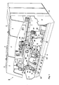
- Fig. 1 eine perspektivische Gesamtansicht einer Dosenschweißmaschine mit einer erfindungsgemäßen Fördereinrichtung,
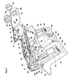
- Fig. 2 eine Schrägansicht in Richtung des Pfeils II in Fig. 1 von Baugruppen der Maschine in teilweise zerlegtem Zustand,
- Fig. 3 die Draufsicht der Maschine,
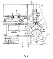
- Fig. 4 die Seitenansicht in Richtung des Pfeils IV in Fig. 3,
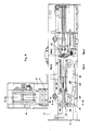
- Fig. 5a den Teilschnitt V-V in Fig. 3 in einer Einstellung und Ausrüstung der Maschine zum Schweißen großer Dosenzargen,
- Fig. 5b den Teilschnitt V-V in Fig. 3 in einer Einstellung und Ausrüstung der Maschine zum Schweißen kleiner Dosenzargen,
- Fig. 6 eine vervollständigte Einzelheit aus Fig. 5a,
- Fig. 7 den Teilschnitt VII-VII in Fig. 3, und
- Fig. 8 den Teilschnitt VIII-VIII in Fig. 3.
- 1 is an overall perspective view of a can welding machine with a conveyor device according to the invention,
- 2 is an oblique view in the direction of arrow II in Fig. 1 of assemblies of the machine in a partially disassembled state,
- 3 is a top view of the machine,
- 4 shows the side view in the direction of arrow IV in FIG. 3,
- 5a shows the partial section VV in Fig. 3 in an adjustment and equipment of the machine for welding large can bodies,
- 5b shows the partial section VV in Fig. 3 in an adjustment and equipment of the machine for welding small can bodies,
- 6 shows a completed detail from FIG. 5a,
- Fig. 7 shows the partial section VII-VII in Fig. 3, and
- 8 shows the partial section VIII-VIII in FIG. 3.
Zweck der dargestellten Maschine ist es, aus ebenen, rechteckigen Blechplatinen Dosenzargen 1 zu runden und deren Längsränder 2 miteinander zu verschweißen.The purpose of the machine shown is to
Die Maschine hat ein langgestrecktes Maschinenbett 3, das an seinen Enden durch Stirnwände 4 begrenzt ist, und das durch Zwischenwände 5 unterteilt ist. Am Maschinengestell 3 ist ein in gleicher Richtung langgestreckter, portalartiger Rahmen 6 befestigt, an dem schwenkbare Abdeckungen 7 angelenkt sind. An einen Endbereich des Rahmens 6 schließt sich an dessen vom Maschinenbett 3 abgewandter Seite ein Schaltkasten 8 an. An den anderen Endbereich schließt sich auf der gleichen Seite ein Gehäuse 9 an.The machine has an
Auf dem Gehäuse 9 ist ein Abstapler 10 angeordnet, der in üblicher Weise dazu bestimmt ist, ebene Blechplatinen einzeln einem Stapel zu entnehmen und zu einem Flexer 11 zu fördern, der jede einzelne Blechplatine durch mehrfaches Biegen von inneren Spannungen befreit und einer Rundstation 12 zuführt.Arranged on the
Am Übergang zwischen Flexer 11 und Rundstation 12 ist ein Keil 13 angeordnet, über den jede einzelne Blechplatine zwischen eine untere Walze 14 und eine obere Walze 15 einläuft. Die untere Walze 14 ist an einem Arm 16 gelagert, der mit einem seiner Enden am Rahmen 6 befestigt ist und sich von dort aus über die Rundstation 12 hinaus waagerecht längs eines großen Teils des Rahmens 6, etwa auf dessen halber Höhe, erstreckt. Die obere Walze 15 ist an einer Konsole 17 gelagert, die sich oberhalb des Arms 16 quer zu diesem erstreckt und mit einem ihrer Enden am Rahmen 6 befestigt ist.A
Zur Rundstation 12 gehören ferner ein schalenartiges unteres Führungselement 18 und zwei ebenfalls schalenartige obere Führungselemente 19, die je einen ringsektorförmigen Querschnitt haben und rings um den Arm 16 derart angeordnet sind, daß jede einzelne Blechplatine von den Walzen 14 und 15 in einen Zwischenraum zwischen diesen Führungselementen und dem Arm 16 gefördert wird und dabei die gewünschte zylindrische Form einer Dosenzarge 1 annimmt.The
Im folgenden wird von allem die Fördereinrichtung beschrieben, mit der die Dosenzargen 1 einzeln von der Rundstation 12 weg längs des Arms 16 weitergefördert werden.The conveyor device with which the
Unterhalb der Rundstation 12 wird das Maschinenbett 3 von einem Gestell 20 überbrückt, das in seiner Form einem Sat teldach mit offenem First ähnlich ist. Auf dem Gestell 20 sind zwei Führungen 21 angeordnet, die sich auf je einer schrägen Seite des Gestells, im rechten Winkel zueinander, radial zum Arm 16 hin nach oben erstrecken und gegen eine waagerechte Ebene um je 45° geneigt sind. Auf jeder der Führungen 21 ist ein Schlitten 22 geführt und mittels eines Stelltriebs 23, der beispielsweise eine Gewindespindel aufweist, mit hoher Genauigkeit zur Anpassung an Dosenzargen 1 unterschiedlicher Durchmesser verstellbar. Derjenige der beiden Schlitten 22, der auf der Bedienungsseite der Maschine angeordnet, also dem Betrachter der Fig. 1 zugewandt ist, läßt sich unabhängig vom Stelltrieb 23 auch mittels eines Eilgangantriebs 23′ verstellen, damit der Arm 16 rasch freigemacht werden kann, wenn beispielsweise eine Störung behoben werden muß.Below the
Jeder der Schlitten 22 trägt ein Getriebe 24, aus dem eine Antriebswelle 25 nach oben herausragt. Die Antriebswellen 25 liegen in einer gemeinsamen senkrechten, in bezug auf den Arm 16 querliegenden Ebene und schließen mit der senkrechten Längsmittelebene des Arms 16 einen Winkel von je 45° ein.Each of the
Am Getriebe 24 jedes der beiden Schlitten 22 ist ein auswechselbarer Strangträger 26 befestigt, der eine gewisse Ähnlichkeit mit dem Kettenschwert einer Kettensäge hat. Jeder Strangträger 26 hat eine Aussparung 27 für die zugehörige Antriebswelle 25 und hat ferner ein Paar Zentrierlöcher 28, die einander in bezug auf die Aussparung 27 ungefähr diametral gegenüberliegen und je einem am Gehäuse des zugehörigen Getriebes 24 angeordneten Bolzen 29 zugeordnet sind. Jeder Strangträger 26 ist auf die zugehörigen Bolzen 29 aufgesteckt, durch diese zentriert und mit nicht dargestellten, schnell lösbaren Gewindemuttern festgehalten.An
An jedem der Strangträger 26 ist ein endloser Förderstrang 30 geführt, der im dargestellten Beispiel von einer Laschenkette mit in gleichmäßigen Abständen angeordneten Mitnehmern 31 gebildet ist, aber auch beispielsweise von einem Zahnriemen gebildet sein könnte. Jeder Förderstrang 30 läuft über ein Paar Umlenkvorrichtungen 32, die im dargestellten Beispiel je ein Kettenrad aufweisen. Die Umlenkvorrichtungen 32 sind derart angeordnet, daß ein Trum jedes Förderstrangs 30 sich parallel zum Arm 16 erstreckt, und der Förderstrang insgesamt stets gleichmäßig gespannt gehalten ist. Jedem Förderstrang 30 ist ferner ein Antriebsrad 33, im dargestellten Beispiel ebenfalls ein Kettenrad, zugeordnet, das sich auf die zugehörige Antriebswelle 25 aufstecken und an dieser mittels einer schnell lösbaren Kupplung 34 befestigen läßt.On each of the
Die Antriebswellen 25 der beiden Schlitten 22 sind durch das jeweils zugehörige Getriebe 24 mit je einer Gelenkwelle 35 und über diese mit je einer weiteren Gelenkwelle 36 verbunden. Die beiden Gelenkwellen 36 gehen von einem Verzweigungsgetriebe 37 aus, das an einer der Zwischenwände 5 befestigt und von einem Motor 38 antreibbar ist.The
Vom Motor 38 werden ferner über eine Gelenkwelle 39 der Flexer 11 und die Walzen 14 und 15 in der Rundstation 12 angetrieben. Diese für die Zufuhr der Blechplatinen zur Rundstation 12 verantwortlichen Förderelemente sind also mit den Fördersträngen 30 synchronisiert. Auf diese Weise ist dafür gesorgt, daß jede Dosenzarge 11, die in der Rundstation 12 um den Arm 16 herum gerundet worden ist, von zwei Mitnehmern 31 erfaßt wird, die zu je einem der beiden Förderstränge 30 gehören und die Dosenzarge längs des Arms 16 von der Rundstation 12 wegbewegen.The
In einem Abstand förderstromabwärts vom Gestell 20 ist ein weiteres, gleichartiges Gestell 40 auf dem Maschinenbett 3 angeordnet. Das Gestell 40 weist ein Paar Führungen 41 auf, die den Führungen 21 entsprechen und je einen Schlitten 42 führen, der mittels eines Stelltriebs 43 in Form einer Gewindespindel mit hoher Genauigkeit zur Anpassung an Dosenzargen 1 unterschiedlicher Durchmesser verstellbar ist. Derjenige der beiden Schlitten 42, der auf der Bedienungsseite der Maschine angeordnet, also dem Betrachter der Fig. 1 zugewandt ist, läßt sich außerdem, unabhängig vom Stelltrieb 43, mittels eines Eilgangantriebs 43′ vom Arm 16 weg verstellen, damit dieser rasch zugänglich gemacht werden kann, ohne daß sich an der Einstellung des Stelltriebs 43 etwas ändert. Die beiden Eilgangantriebe 23′ und 43′ sind stets gemeinsam und gleichsinnig betätigbar.A further,
Jeder der beiden Schlitten 42 trägt ein Getriebe 44 mit einer Antriebswelle 45. Jedes der beiden Getriebe 44 verbindet die beiden zugehörigen Gelenkwellen 35 und 36 miteinander und mit der betreffenden Antriebswelle 45. Auf das Getriebe 44 jedes der beiden Schlitten 42 ist ein Strangträger 46 aufgesteckt, der zu diesem Zweck eine Aussparung 47 für die Antriebswelle 45 sowie ein Paar Löcher 48 für ein Paar am Getriebe 44 befestigter Bolzen 49 aufweist und leicht auswechselbar ist.Each of the two
Jeder Strangträger 46 trägt einen Förderstrang 50, der wiederum von einer Laschenkette mit Mitnehmern 51 gebildet ist. Jeder der beiden Förderstränge 50 läuft über ein Paar Umlenkvorrichtungen 52 und ist von einem Antriebsrad 53 antreibbar, das sich auf die zugehörige Antriebswelle 45 aufstecken und an dieser mittels einer schnell lösbaren Kupplung 54 befestigen läßt.Each
Die Gestelle 20 und 40 sind in der Art von Bettschlitten längs des Maschinenbetts 3, also parallel zum Arm 16, verstellbar. Für gemeinsame Bewegungen sind die beiden Gestelle 20 und 40 miteinander durch eine längeneinstellbare Gewindestange 55 verbunden. Am Gestell 40 ist ein Zahnradgetriebe 56 angeordnet, das sich mit einem Handrad 57 antreiben läßt und mit einer am Maschinenbett 3 befestigten, nicht dargestellten Zahnstange zusammenwirkt, um die Gestelle 20 und 40 zu verstellen.The
Das beschriebene untere Führungselement 18 in der Rundstation 12 ist auf einer Stütze 58 befestigt, die ihrerseits mittels einer Klemmleiste 59 einstellbar am Gehäuse des Getriebes 24 auf demjenigen der beiden Schlitten 22 befestigt ist, der auf der Bedienungsseite der Maschine angeordnet und, wie beschrieben, im Eilgang verstellbar ist. Dieser Schlitten 22 ist in Fig. 5b in einer vom Arm 16 entfernten Ruhestellung abgebildet. Dabei ist die Entfernung zwischen der Arbeitsstellung und der Ruhestellung des betreffenden Schlittens 22 mit einem Pfeil angedeutet.The described
Im Bereich der Strangträger 46, also in einem Abstand förderstromabwärts von der Rundstation 12, sind gemäß Fig. 7 unterhalb des Arms 16 weitere Führungselemente 60 in Gestalt von Rollenpaaren angeordnet, die auf Rollenträgern 61 gelagert sind. An jedem Rollenträger 61 ist außerdem eine Magnetleiste 62 befestigt, die dafür sorgt, daß die Dosenzargen 1 gleichmäßig an den Führungselementen 60 anliegen. Jeder Rollenträger 61 ist über Stützen 63 an einer nach unten offenen U-Schiene 64 einstellbar befestigt, und diese ist wiederum an einer nach oben offenen U-Schiene 65 gehalten, die ihrerseits mittels eines Handgriffs 66 schnell lösbar an einer Konsole 67 festgeklemmt ist. Jede der Konsolen 67 ist am Getriebe 44 auf demjenigen der beiden Schlitten 42 befestigt, der auf der Bedie nungsseite der Maschine angeordnet und, wie beschrieben, ebenfalls im Eilgang verstellbar ist. Auch dieser Schlitten 42 ist in Fig. 7 in einer vom Arm 16 entfernten Ruhestellung abgebildet. Dabei ist wiederum die Entfernung zwischen der Arbeitsstellung und der Ruhestellung des betreffenden Schlittens 42 mit einem Pfeil angedeutet.In the area of the
Im Arbeitsbereich der beiden Förderstränge 50 ist auf der Oberseite des Arms 16 eine Z-Schiene 68 befestigt, die in üblicher Weise die Längsränder 2 der Dosenzargen 1 führt. Parallel zur Z-Schiene 68 und auf gleicher Höhe wie diese ist ein Paar Stromschienen 69 angeordnet, die eine Schweißstation 70 mit Strom versorgen. Die Schweißstation 70 ist von üblicher Bauart und weist vor allem ein Paar Elektrodenrollen 71 und 72 zum Verschweißen der Längsränder 2 der Dosenzargen 1 auf.In the working area of the two
Wenn die gemäß Fig. 5a zum Herstellen großer Dosenzargen 1 ausgerüstete Maschine derart umgerüstet werden soll, daß sie sehr viel kleinere Dosenzargen herstellen kann, und wenn ein solches Umrüsten durch bloße Verstellung der Schlitten 22 und 42 nicht möglich ist, werden die ursprünglich verwendeten Strangträger 26 und 46 samt ihren Fördersträngen 30 bzw. 50 und Umlenkvorrichtungen 32 bzw. 52, nötigenfalls einschließlich des jeweils zugehörigen Antriebsrades 33 bzw. 53, durch entsprechend anders gestaltete Strangträger 26 bzw. 46 ersetzt. Nötigenfalls werden auch die Führungselemente 18,19 und 60 ausgewechselt.If the machine equipped according to FIG. 5a for the production of large can
Claims (8)
dadurch gekennzeichnet, daß
- die Umlenkvorrichtungen (32; 52) an einem Strangträger (26; 46) gelagert sind und mit diesem sowie dem zugehörigen Förderstrang (30; 50) eine insgesamt auswechselbare, der Länge der Dosenzargen (1) angepaßte Einheit bilden, und
- diese Einheit an einem Schlitten (22; 42) befestigt ist, der mindestens annähernd radial zum Arm (16) verstellbar ist.1. Conveying device for can bodies on a can welding machine with an arm (16), around which the can bodies (1) are rounded, and at least one endless conveyor line (30; 50), which has deflection devices (32; 52) and a drive wheel (33 ; 53) is guided and has a run parallel to the arm (16) in order to convey the can bodies (1) along the arm (16) towards a welding station (70),
characterized in that
- The deflection devices (32; 52) are mounted on a strand carrier (26; 46) and form with this and the associated conveyor strand (30; 50) an overall interchangeable unit, the length of the can bodies (1), and
- This unit is attached to a carriage (22; 42) which is at least approximately radially adjustable to the arm (16).
dadurch gekennzeichnet, daß
- jedem Förderstrang (30; 50) ein eigener Strangträger (26; 46) sowie ein eigener Schlitten (22; 42) zugeordnet ist und
- die beiden Schlitten (22; 42) jedes Paars auf Führungen (21; 41) verstellbar sind, die sich auf je einer Seite einer Längsmittelebene des Arms (16) in Richtung zu diesem hin schräg aufwärts erstrecken.2. Conveying device according to claim 1 with at least one pair of endless conveyor strands (50) which act together and simultaneously on the can bodies (1),
characterized in that
- Each conveyor train (30; 50) is assigned its own strand carrier (26; 46) and its own carriage (22; 42) and
- The two carriages (22; 42) of each pair on guides (21; 41) are adjustable, each of which extends obliquely upwards on one side of a longitudinal median plane of the arm (16).
dadurch gekennzeichnet, daß Führungselemente (18; 60) für die Dosenzargen (1) einstellbar an einem der Schlitten (22; 42) befestigt sind.3. Conveyor device according to claim 1 or 2,
characterized in that guide elements (18; 60) for the can bodies (1) are adjustably attached to one of the slides (22; 42).
dadurch gekennzeichnet, daß beiden Schlitten (22; 42) jedes Schlittenpaars für eine genaue Einstellung entsprechend dem Durchmesser der Dosenzargen (1) ein eigener Stelltrieb (23; 43) zugeordnet ist und mindestens einem der beiden Schlitten (22; 42) jedes Schlittenpaars, der an einer für eine Bedienungsperson gut zugänglichen Seite der Dosenschweißmaschine angeordnet ist, ein unabhänig von seinem Stelltrieb (23; 43) betätigbarer Eilgangantrieb (23′; 43′) zum Freimachen des Arms (16) zugeordnet ist.4. Conveyor device according to claim 2,
characterized in that the two slides (22; 42) of each pair of slides are assigned a separate actuating drive (23; 43) for precise adjustment according to the diameter of the can bodies (1) and at least one of the two slides (22; 42) of each pair of slides which is arranged on a side of the can welding machine which is easily accessible for an operator, a rapid-motion drive (23 ';43') which can be actuated independently of its actuating drive (23; 43 ') for releasing the arm (16).
dadurch gekennzeichnet, daß jeder Strangträger (26; 46) auf ein am zugehörigen Schlitten (22; 42) befestigtes Getriebe (24; 44) aufgesteckt ist, das eine mit dem Antriebsrad (33; 53) kuppelbare Antriebswelle (25; 45) aufweist.5. Conveyor device according to one of claims 1 to 4,
characterized in that each strand carrier (26; 46) is plugged onto a gear (24; 44) fastened to the associated slide (22; 42) and having a drive shaft (25; 45) which can be coupled to the drive wheel (33; 53).
dadurch gekennzeichnet, daß die Antriebswellen (25; 45) an den Schlitten (22; 42) über je eine Gelenkwelle (35; 36) von einem gemeinsamen Motor (38) antreibbar sind.6. Conveyor device according to claim 5,
characterized in that the drive shafts (25; 45) on the slides (22; 42) can each be driven by a common motor (38) via an articulated shaft (35; 36).
dadurch gekennzeichnet, daß jeder vorgeschaltete Förderstrang (30) in entsprechender Weise wie der auf ihn folgende, die Dosenzargen (1) zur Schweißstation (70) fördernde Förderstrang (50) Bestandteil einer auswechselbar auf einem Schlitten (42) angeordneten, der Länge der Dosenzargen (1) angepaßten Einheit ist.7. Conveyor device according to one of claims 1 to 6, in which each endless conveyor line (50) which conveys the can bodies (1) to the welding station (70) is preceded by a conveyor line (30) which the can bodies (1) from a round station (12) takes over
characterized in that each upstream conveyor line (30), in a manner corresponding to the subsequent conveyor line (50) conveying the can bodies (1) to the welding station (70), is part of an interchangeably arranged on a slide (42), the length of the can bodies ( 1) customized unit.
dadurch gekennzeichnet, daß jedem vorgeschalteten Förderstrang (30) ein Getriebe (24) zugeordnet ist, das mit dem Getriebe (44) für den auf ihn folgenden Förderstrang (50) durch eine Gelenkwelle (35) verbunden ist.8. Conveyor device according to claims 6 and 7,
characterized in that each upstream conveyor line (30) is assigned a gear (24) which is connected to the gear (44) for the conveyor line (50) following it by means of a cardan shaft (35).
Applications Claiming Priority (2)
| Application Number | Priority Date | Filing Date | Title |
|---|---|---|---|
| CH1737/87A CH671945A5 (en) | 1987-05-07 | 1987-05-07 | |
| CH1737/87 | 1987-05-07 |
Publications (3)
| Publication Number | Publication Date |
|---|---|
| EP0289744A2 true EP0289744A2 (en) | 1988-11-09 |
| EP0289744A3 EP0289744A3 (en) | 1989-05-03 |
| EP0289744B1 EP0289744B1 (en) | 1991-08-14 |
Family
ID=4217404
Family Applications (1)
| Application Number | Title | Priority Date | Filing Date |
|---|---|---|---|
| EP19880103850 Expired - Lifetime EP0289744B1 (en) | 1987-05-07 | 1988-03-11 | Conveyor for can shells in a can welding machine |
Country Status (17)
| Country | Link |
|---|---|
| US (1) | US4870241A (en) |
| EP (1) | EP0289744B1 (en) |
| JP (1) | JPS63281782A (en) |
| KR (1) | KR920004662B1 (en) |
| CN (1) | CN1009172B (en) |
| AU (1) | AU602644B2 (en) |
| BR (1) | BR8802219A (en) |
| CA (1) | CA1283882C (en) |
| CH (1) | CH671945A5 (en) |
| DE (2) | DE3736002A1 (en) |
| DK (1) | DK251488A (en) |
| ES (1) | ES2025230B3 (en) |
| FI (1) | FI882069A (en) |
| GR (1) | GR3003032T3 (en) |
| NO (1) | NO167554C (en) |
| RU (1) | RU1787094C (en) |
| ZA (1) | ZA882554B (en) |
Cited By (4)
| Publication number | Priority date | Publication date | Assignee | Title |
|---|---|---|---|---|
| AU602644B2 (en) * | 1987-05-07 | 1990-10-18 | Elpatronic A.G. | Conveyor device for can bodies in a can welding machine |
| EP0523377A1 (en) * | 1991-07-19 | 1993-01-20 | Elpatronic Ag | Device for delivering thin sheet to a can welding machine |
| EP0696486A1 (en) * | 1994-08-10 | 1996-02-14 | Elpatronic Ag | Method and device for bending sheet metal blanks |
| WO2008144947A1 (en) * | 2007-05-30 | 2008-12-04 | Soudronic Ag | Method and device for adjusting a flexing station during the bending of sheet metal |
Families Citing this family (13)
| Publication number | Priority date | Publication date | Assignee | Title |
|---|---|---|---|---|
| CH680714A5 (en) * | 1989-08-22 | 1992-10-30 | Elpatronic Ag | |
| US5209625A (en) * | 1989-08-22 | 1993-05-11 | Elpatronic Ag | Apparatus for rounding and conveying onwards sheet-metal blanks for can bodies |
| DE3932551C2 (en) * | 1989-09-29 | 1998-07-09 | Krupp Kunststofftechnik Gmbh | Device for feeding rounded can bodies into the area of a welding unit |
| DE59503065D1 (en) * | 1994-11-28 | 1998-09-10 | Elpatronic Ag | Process for commissioning or retrofitting a frame welding machine and a modular magazine for carrying out the process |
| DE29813669U1 (en) | 1998-07-31 | 1999-12-23 | KUKA Schweissanlagen GmbH, 86165 Augsburg | Flexible work station |
| US7992276B2 (en) * | 2006-10-24 | 2011-08-09 | GM Global Technology Operations LLC | Fixture exchange rail system and method of use |
| CN105033428B (en) * | 2015-07-02 | 2017-10-13 | 东莞市联洲知识产权运营管理有限公司 | A kind of welding equipment |
| CH713656A1 (en) * | 2017-03-29 | 2018-10-15 | Can Man Ag | Method for rounding sheet metal blanks for containers and a longitudinal seam welding machine for the production of can bodies with a round station. |
| CN109500281B (en) * | 2018-12-24 | 2023-09-29 | 深圳华特容器股份有限公司 | Adjustable tank body oblique expanding machine |
| CN110102927B (en) * | 2019-05-17 | 2024-07-19 | 佛山市顺德区杰峰工业自动化有限公司 | Automatic tank welding equipment |
| CN112960350B (en) * | 2021-02-02 | 2024-06-11 | 广州市通海金属制品有限公司 | Metal can processing production line |
| CN114535887B (en) * | 2022-04-24 | 2022-06-28 | 深圳市米里汽车电子有限公司 | Welding device for automobile seat framework |
| CN114985181B (en) * | 2022-05-18 | 2023-05-30 | 珠海格力智能装备有限公司 | Paint spraying and drying production line |
Citations (6)
| Publication number | Priority date | Publication date | Assignee | Title |
|---|---|---|---|---|
| US2236747A (en) * | 1939-02-23 | 1941-04-01 | Cameron Can Machinery Co | Feeding device for can bodies |
| US4050394A (en) * | 1976-04-09 | 1977-09-27 | Libby, Mcneil & Libby | Can fabrication system |
| CH621499A5 (en) * | 1977-06-10 | 1981-02-13 | Paul Opprecht | |
| US4497995A (en) * | 1982-04-15 | 1985-02-05 | Sws Incorporated | Apparatus for continuously advancing and welding metal can bodies and the like |
| US4574176A (en) * | 1983-11-28 | 1986-03-04 | Sws Incorporated | Method and apparatus for pulsed high energy density welding |
| EP0215404A1 (en) * | 1985-09-09 | 1987-03-25 | Elpatronic Ag | Body guide on a machine for the butt-welding of can bodies |
Family Cites Families (7)
| Publication number | Priority date | Publication date | Assignee | Title |
|---|---|---|---|---|
| US2432490A (en) * | 1944-10-30 | 1947-12-09 | Taylor Winfield Corp | Tubular body maker and conveyor |
| US3584178A (en) * | 1969-04-09 | 1971-06-08 | Nat Can Corp | Can body welding machine |
| NL183178C (en) * | 1978-06-21 | 1988-08-16 | Hoogovens Ijmuiden Bv | COMPOSITE TRANSPORTER. |
| IT1169112B (en) * | 1983-02-24 | 1987-05-27 | Augusto Marchetti | TAPING MACHINE WITH ADJUSTABLE DISTANCE DRIVING UNIT |
| US4694953A (en) * | 1985-06-12 | 1987-09-22 | Automation Service Equipment, Inc. | Drive for double gripper chain conveyor |
| FR2586657B1 (en) * | 1985-09-04 | 1991-03-22 | Lapouyade Sa | DEVICE FOR GRIPPING SUPPORTS OR LOAD CONTAINERS |
| CH671945A5 (en) * | 1987-05-07 | 1989-10-13 | Elpatronic Ag |
-
1987
- 1987-05-07 CH CH1737/87A patent/CH671945A5/de not_active IP Right Cessation
- 1987-10-23 DE DE19873736002 patent/DE3736002A1/en active Granted
-
1988
- 1988-03-11 DE DE8888103850T patent/DE3864182D1/en not_active Expired - Lifetime
- 1988-03-11 ES ES88103850T patent/ES2025230B3/en not_active Expired - Lifetime
- 1988-03-11 EP EP19880103850 patent/EP0289744B1/en not_active Expired - Lifetime
- 1988-03-25 US US07/173,279 patent/US4870241A/en not_active Expired - Lifetime
- 1988-04-11 KR KR1019880004099A patent/KR920004662B1/en not_active IP Right Cessation
- 1988-04-12 ZA ZA882554A patent/ZA882554B/en unknown
- 1988-04-18 CA CA000564360A patent/CA1283882C/en not_active Expired - Lifetime
- 1988-04-18 AU AU14712/88A patent/AU602644B2/en not_active Ceased
- 1988-04-25 CN CN88102515A patent/CN1009172B/en not_active Expired
- 1988-04-28 JP JP63104404A patent/JPS63281782A/en active Granted
- 1988-05-04 FI FI882069A patent/FI882069A/en not_active IP Right Cessation
- 1988-05-06 DK DK251488A patent/DK251488A/en not_active Application Discontinuation
- 1988-05-06 NO NO881988A patent/NO167554C/en unknown
- 1988-05-06 BR BR8802219A patent/BR8802219A/en not_active IP Right Cessation
- 1988-05-07 RU SU884355640A patent/RU1787094C/en active
-
1991
- 1991-10-31 GR GR91401177T patent/GR3003032T3/en unknown
Patent Citations (6)
| Publication number | Priority date | Publication date | Assignee | Title |
|---|---|---|---|---|
| US2236747A (en) * | 1939-02-23 | 1941-04-01 | Cameron Can Machinery Co | Feeding device for can bodies |
| US4050394A (en) * | 1976-04-09 | 1977-09-27 | Libby, Mcneil & Libby | Can fabrication system |
| CH621499A5 (en) * | 1977-06-10 | 1981-02-13 | Paul Opprecht | |
| US4497995A (en) * | 1982-04-15 | 1985-02-05 | Sws Incorporated | Apparatus for continuously advancing and welding metal can bodies and the like |
| US4574176A (en) * | 1983-11-28 | 1986-03-04 | Sws Incorporated | Method and apparatus for pulsed high energy density welding |
| EP0215404A1 (en) * | 1985-09-09 | 1987-03-25 | Elpatronic Ag | Body guide on a machine for the butt-welding of can bodies |
Cited By (4)
| Publication number | Priority date | Publication date | Assignee | Title |
|---|---|---|---|---|
| AU602644B2 (en) * | 1987-05-07 | 1990-10-18 | Elpatronic A.G. | Conveyor device for can bodies in a can welding machine |
| EP0523377A1 (en) * | 1991-07-19 | 1993-01-20 | Elpatronic Ag | Device for delivering thin sheet to a can welding machine |
| EP0696486A1 (en) * | 1994-08-10 | 1996-02-14 | Elpatronic Ag | Method and device for bending sheet metal blanks |
| WO2008144947A1 (en) * | 2007-05-30 | 2008-12-04 | Soudronic Ag | Method and device for adjusting a flexing station during the bending of sheet metal |
Also Published As
| Publication number | Publication date |
|---|---|
| NO881988D0 (en) | 1988-05-06 |
| DE3864182D1 (en) | 1991-09-19 |
| FI882069A0 (en) | 1988-05-04 |
| NO167554B (en) | 1991-08-12 |
| JPH0337838B2 (en) | 1991-06-06 |
| CA1283882C (en) | 1991-05-07 |
| CN1009172B (en) | 1990-08-15 |
| CN88102515A (en) | 1988-11-23 |
| FI882069A (en) | 1988-11-08 |
| GR3003032T3 (en) | 1993-02-17 |
| NO167554C (en) | 1991-11-20 |
| DE3736002C2 (en) | 1989-02-16 |
| BR8802219A (en) | 1988-12-06 |
| JPS63281782A (en) | 1988-11-18 |
| AU602644B2 (en) | 1990-10-18 |
| EP0289744B1 (en) | 1991-08-14 |
| DK251488A (en) | 1988-11-08 |
| CH671945A5 (en) | 1989-10-13 |
| DK251488D0 (en) | 1988-05-06 |
| US4870241A (en) | 1989-09-26 |
| ZA882554B (en) | 1989-12-27 |
| AU1471288A (en) | 1988-11-10 |
| RU1787094C (en) | 1993-01-07 |
| ES2025230B3 (en) | 1992-03-16 |
| EP0289744A3 (en) | 1989-05-03 |
| DE3736002A1 (en) | 1988-11-17 |
| KR920004662B1 (en) | 1992-06-13 |
| NO881988L (en) | 1988-11-08 |
| KR880013634A (en) | 1988-12-21 |
Similar Documents
| Publication | Publication Date | Title |
|---|---|---|
| EP0289744B1 (en) | Conveyor for can shells in a can welding machine | |
| EP1849536B1 (en) | Bending machine for rod-shaped workpieces like wire or tube | |
| EP0289748B1 (en) | Calibrating tool for a straight bead welding machine for rounded can shells | |
| EP0243795B1 (en) | Device for guiding rounded borders through a welding zone | |
| EP0241449B1 (en) | Resistance multi-spot welding machine | |
| DE3105312C2 (en) | Automatic pipe circumference welding device | |
| EP0705655A1 (en) | Work machine with relative movable rotating devices | |
| EP0420018B1 (en) | Rounded cans bodies feeding device for a welding unit | |
| DE2849751C2 (en) | Device for separating cut-to-length wires forming a loose bundle, in particular for feeding wire to a processing machine | |
| WO2002070164A1 (en) | Device for cutting metal strips to length | |
| EP0182071B1 (en) | Device for stacking flat objets equipped with two register holes, especially bags made from a plastic web | |
| EP0212620B1 (en) | Machine for welding together the longitudinal edges of rounded bodies | |
| DE69129077T2 (en) | METHOD AND DEVICE FOR CUTTING PIPES IN WHICH THE PIPES ARE BROUGHT IN A CUTTING POSITION BY MEANS OF A ROTATING FIXING PLATE | |
| DE102010005757B3 (en) | Device and method for guiding strips to be joined together along their longitudinal edges | |
| EP0054890A1 (en) | Workpiece conveyor, particularly for small pieces | |
| EP3369685A1 (en) | Device for transporting elongated pieces to a pick-up position and for depositing elongated pieces at this position | |
| EP0159622B1 (en) | Screen printer with an immobile printing table | |
| DE509520C (en) | Folding machine | |
| DE4232530C2 (en) | straightening table | |
| EP0499797A1 (en) | Alignment device for woods to be machined | |
| EP4412929A1 (en) | Product conveyor device for supplying food products to a slicing unit | |
| DE2600191C2 (en) | Transport and turning device for a nut press | |
| DE2534753A1 (en) | CARDBOARD MAKING MACHINE | |
| DE2409833A1 (en) | Resistance butt welding machine for chain links - with automatic switch off if link mal-alignment occurs | |
| DE1435070C (en) | Pleating machine |
Legal Events
| Date | Code | Title | Description |
|---|---|---|---|
| PUAI | Public reference made under article 153(3) epc to a published international application that has entered the european phase |
Free format text: ORIGINAL CODE: 0009012 |
|
| AK | Designated contracting states |
Kind code of ref document: A2 Designated state(s): BE CH DE ES FR GB GR IT LI NL SE |
|
| PUAL | Search report despatched |
Free format text: ORIGINAL CODE: 0009013 |
|
| AK | Designated contracting states |
Kind code of ref document: A3 Designated state(s): BE CH DE ES FR GB GR IT LI NL SE |
|
| 17P | Request for examination filed |
Effective date: 19890410 |
|
| 17Q | First examination report despatched |
Effective date: 19900502 |
|
| GRAA | (expected) grant |
Free format text: ORIGINAL CODE: 0009210 |
|
| AK | Designated contracting states |
Kind code of ref document: B1 Designated state(s): BE CH DE ES FR GB GR IT LI NL SE |
|
| GBT | Gb: translation of ep patent filed (gb section 77(6)(a)/1977) | ||
| ITF | It: translation for a ep patent filed | ||
| REF | Corresponds to: |
Ref document number: 3864182 Country of ref document: DE Date of ref document: 19910919 |
|
| ET | Fr: translation filed | ||
| RAP4 | Party data changed (patent owner data changed or rights of a patent transferred) |
Owner name: ELPATRONIC AG |
|
| REG | Reference to a national code |
Ref country code: ES Ref legal event code: FG2A Ref document number: 2025230 Country of ref document: ES Kind code of ref document: B3 |
|
| PLBE | No opposition filed within time limit |
Free format text: ORIGINAL CODE: 0009261 |
|
| STAA | Information on the status of an ep patent application or granted ep patent |
Free format text: STATUS: NO OPPOSITION FILED WITHIN TIME LIMIT |
|
| 26N | No opposition filed | ||
| REG | Reference to a national code |
Ref country code: GR Ref legal event code: FG4A Free format text: 3003032 |
|
| PGFP | Annual fee paid to national office [announced via postgrant information from national office to epo] |
Ref country code: GR Payment date: 19931223 Year of fee payment: 7 |
|
| EAL | Se: european patent in force in sweden |
Ref document number: 88103850.9 |
|
| PGFP | Annual fee paid to national office [announced via postgrant information from national office to epo] |
Ref country code: BE Payment date: 19950220 Year of fee payment: 8 |
|
| PGFP | Annual fee paid to national office [announced via postgrant information from national office to epo] |
Ref country code: ES Payment date: 19950307 Year of fee payment: 8 |
|
| PG25 | Lapsed in a contracting state [announced via postgrant information from national office to epo] |
Ref country code: GR Free format text: THE PATENT HAS BEEN ANNULLED BY A DECISION OF A NATIONAL AUTHORITY Effective date: 19950930 |
|
| REG | Reference to a national code |
Ref country code: GR Ref legal event code: MM2A Free format text: 3003032 |
|
| PG25 | Lapsed in a contracting state [announced via postgrant information from national office to epo] |
Ref country code: ES Free format text: LAPSE BECAUSE OF NON-PAYMENT OF DUE FEES Effective date: 19960312 |
|
| PG25 | Lapsed in a contracting state [announced via postgrant information from national office to epo] |
Ref country code: BE Effective date: 19960331 |
|
| BERE | Be: lapsed |
Owner name: ELPATRONIC A.G. Effective date: 19960331 |
|
| REG | Reference to a national code |
Ref country code: ES Ref legal event code: FD2A Effective date: 19990405 |
|
| REG | Reference to a national code |
Ref country code: CH Ref legal event code: PFA Free format text: ELPATRONIC AG,HERTIZENTRUM 6,6303 ZUG (CH) TRANSFER- ELPATRONIC AG,INDUSTRIESTRASSE 35,8962 BERGDIETIKON (CH) |
|
| REG | Reference to a national code |
Ref country code: GB Ref legal event code: IF02 |
|
| PGFP | Annual fee paid to national office [announced via postgrant information from national office to epo] |
Ref country code: NL Payment date: 20060314 Year of fee payment: 19 |
|
| PGFP | Annual fee paid to national office [announced via postgrant information from national office to epo] |
Ref country code: GB Payment date: 20060322 Year of fee payment: 19 |
|
| PG25 | Lapsed in a contracting state [announced via postgrant information from national office to epo] |
Ref country code: SE Free format text: LAPSE BECAUSE OF NON-PAYMENT OF DUE FEES Effective date: 20070312 |
|
| PGFP | Annual fee paid to national office [announced via postgrant information from national office to epo] |
Ref country code: CH Payment date: 20070314 Year of fee payment: 20 |
|
| PGFP | Annual fee paid to national office [announced via postgrant information from national office to epo] |
Ref country code: DE Payment date: 20070316 Year of fee payment: 20 |
|
| EUG | Se: european patent has lapsed | ||
| GBPC | Gb: european patent ceased through non-payment of renewal fee |
Effective date: 20070311 |
|
| NLV4 | Nl: lapsed or anulled due to non-payment of the annual fee |
Effective date: 20071001 |
|
| PGFP | Annual fee paid to national office [announced via postgrant information from national office to epo] |
Ref country code: IT Payment date: 20070613 Year of fee payment: 20 |
|
| PG25 | Lapsed in a contracting state [announced via postgrant information from national office to epo] |
Ref country code: NL Free format text: LAPSE BECAUSE OF NON-PAYMENT OF DUE FEES Effective date: 20071001 |
|
| PGFP | Annual fee paid to national office [announced via postgrant information from national office to epo] |
Ref country code: SE Payment date: 20060314 Year of fee payment: 19 |
|
| REG | Reference to a national code |
Ref country code: CH Ref legal event code: PL |
|
| PG25 | Lapsed in a contracting state [announced via postgrant information from national office to epo] |
Ref country code: GB Free format text: LAPSE BECAUSE OF NON-PAYMENT OF DUE FEES Effective date: 20070311 |
|
| PGFP | Annual fee paid to national office [announced via postgrant information from national office to epo] |
Ref country code: FR Payment date: 20070319 Year of fee payment: 20 |