EP0243728B2 - Safety system for a printing machine - Google Patents
Safety system for a printing machine Download PDFInfo
- Publication number
- EP0243728B2 EP0243728B2 EP87104965A EP87104965A EP0243728B2 EP 0243728 B2 EP0243728 B2 EP 0243728B2 EP 87104965 A EP87104965 A EP 87104965A EP 87104965 A EP87104965 A EP 87104965A EP 0243728 B2 EP0243728 B2 EP 0243728B2
- Authority
- EP
- European Patent Office
- Prior art keywords
- safety system
- monitoring circuit
- computers
- braking
- safety
- Prior art date
- Legal status (The legal status is an assumption and is not a legal conclusion. Google has not performed a legal analysis and makes no representation as to the accuracy of the status listed.)
- Expired - Lifetime
Links
- 238000012544 monitoring process Methods 0.000 claims description 21
- 238000004804 winding Methods 0.000 claims description 8
- 230000006870 function Effects 0.000 claims description 5
- 230000015654 memory Effects 0.000 claims description 5
- 230000004913 activation Effects 0.000 claims 2
- 230000003213 activating effect Effects 0.000 claims 1
- 230000011664 signaling Effects 0.000 claims 1
- 230000007547 defect Effects 0.000 description 8
- 238000011161 development Methods 0.000 description 4
- 230000001960 triggered effect Effects 0.000 description 3
- 230000005540 biological transmission Effects 0.000 description 2
- 238000010586 diagram Methods 0.000 description 2
- 239000004065 semiconductor Substances 0.000 description 2
- 235000001674 Agaricus brunnescens Nutrition 0.000 description 1
- 230000001133 acceleration Effects 0.000 description 1
- 230000001934 delay Effects 0.000 description 1
- 230000003111 delayed effect Effects 0.000 description 1
- 238000013461 design Methods 0.000 description 1
- 230000007257 malfunction Effects 0.000 description 1
- 238000000034 method Methods 0.000 description 1
- 230000001681 protective effect Effects 0.000 description 1
- 230000000717 retained effect Effects 0.000 description 1
- 238000000926 separation method Methods 0.000 description 1
- 238000012546 transfer Methods 0.000 description 1
Images

Classifications
-
- B—PERFORMING OPERATIONS; TRANSPORTING
- B41—PRINTING; LINING MACHINES; TYPEWRITERS; STAMPS
- B41F—PRINTING MACHINES OR PRESSES
- B41F33/00—Indicating, counting, warning, control or safety devices
- B41F33/04—Tripping devices or stop-motions
- B41F33/12—Tripping devices or stop-motions for starting or stopping the machine as a whole
-
- B—PERFORMING OPERATIONS; TRANSPORTING
- B41—PRINTING; LINING MACHINES; TYPEWRITERS; STAMPS
- B41F—PRINTING MACHINES OR PRESSES
- B41F13/00—Common details of rotary presses or machines
- B41F13/004—Electric or hydraulic features of drives
- B41F13/0045—Electric driving devices
-
- Y—GENERAL TAGGING OF NEW TECHNOLOGICAL DEVELOPMENTS; GENERAL TAGGING OF CROSS-SECTIONAL TECHNOLOGIES SPANNING OVER SEVERAL SECTIONS OF THE IPC; TECHNICAL SUBJECTS COVERED BY FORMER USPC CROSS-REFERENCE ART COLLECTIONS [XRACs] AND DIGESTS
- Y10—TECHNICAL SUBJECTS COVERED BY FORMER USPC
- Y10S—TECHNICAL SUBJECTS COVERED BY FORMER USPC CROSS-REFERENCE ART COLLECTIONS [XRACs] AND DIGESTS
- Y10S101/00—Printing
- Y10S101/41—Means for braking press cylinders
Definitions
- the invention relates to a security system for a printing press, which is provided with at least one drive and braking device and with an electronic control device.
- the various drives of a printing press are provided with brakes, in which the braking force is exerted by springs and a corresponding voltage is applied to electromagnets to release or release the brakes.
- the brakes are used both as service brakes and for emergencies. This leads to undesirable wear on the brakes.
- emergency stop switches are provided at various points on the printing press and possibly also in the vicinity thereof, with the aid of which the printing press can be stopped. So that the motors can be stopped as well as the brakes applied without electrical auxiliary energy, in known safety devices the emergency stop switches are each provided with a normally closed contact and connected in series.
- DE-A 19 43 312 describes a drive for printing rollers in printing presses in which an electric motor driving the printing roller in cooperation with in order to achieve a high positioning accuracy in normal printing operation an electrical control circuit for the engine speed and for braking the engine are provided in proportion to a respective number of revolutions.
- switching elements in particular relays, are arranged in the control circuit, which cause the motor to work as a generator.
- the drive in addition to the control circuit, is only designed for speed-proportional acceleration and deceleration of printing rollers of a printing press, and that this drive is not suitable for actuating one or more braking devices as a function of defined speed ratios as part of a safety system, which provide a quick total - or cause partial braking in the event of an emergency or emergency situation.
- controller monitoring is disclosed within an electronic drive control and monitoring system, in which an off command is given if there is a long-standing deviation between the speed setpoint and actual speed value.
- the off command causes an immediate controller disable with delayed switching off of a main contactor, which switches a drive motor to de-energized.
- the object of the invention is to provide a safety system for a printing press which, depending on the speed of the drive device and the respective operating state of the printing press, enables a defined braking of the moving machine elements.
- the machine elements can be safely braked using the control stages and power levels for the electric motor as well as the electromechanical braking device.
- further switches can be connected to inputs of the electronic control device.
- the press can be specifically stopped - depending on which of these switches has been pressed.
- a switch when actuated in the area of the paper feeder, it may be expedient to stop the drive of the paper feeder immediately, but to keep the main drive running until the drive in the Press sheets on the machine have left the machine.
- the measures according to the invention ensure that the motion sequence of the printing press is controlled purely electrically, so that predetermined delays are also possible.
- the electromechanical braking devices are only required if errors occur in the electronic control device.
- a special embodiment of this feature is that the safety circuit is supplied with AC line voltage and that the primary winding of a transformer is connected in series with the first contact pairs, the secondary winding of which is connected via a rectifier to the power stages of the monitoring circuit and the computer or computers.
- This configuration enables the safety circuit to be adapted to semiconductor circuits without the voltage supplying the safety circuit is so low that the series connection of many contacts jeopardizes safe current flow.
- the additional information obtained through the additional contact pairs can be evaluated in various ways.
- the emergency stop switches are used to bring the entire machine to a standstill as quickly as possible in the event of a danger. However, malfunctions are possible which only require the machine to be stopped in successive steps.
- the braking device is actuated by switching off an electromagnet that releases the braking device against a spring force.
- the braking device is designed in accordance with another development such that the printing press also comes to a standstill can be brought when the drive device applies the highest possible torque.
- the electromechanical braking device is used very rarely in the system according to the invention, a defect in the braking device that nevertheless occurs could not be noticed. It is therefore provided according to another development that the braking device is checked by actuating the braking device, controlling the driving device for the highest possible torque and evaluating the actual speed value. The check is preferably carried out after switching on the electronic control device.
- a main drive 61 and various auxiliary drives, of which only two auxiliary drives 71, 72 are shown, are controlled by two computers 52, 53.
- the computers 52, 53 are connected to one another and to control electronics 56 by means of a bus system 55.
- a main drive electronics 6 and an auxiliary drive electronics 7 comprise, in addition to power stages, also associated control stages which are equipped with microprocessors, among other things, in a practically implemented system according to the invention.
- Control electronics 56 has a variety of functions and includes various components. To understand the present invention, however, only the explanation of a monitoring circuit, which is part of the control electronics 56, is required.
- the monitoring circuit is supplied by a tachometer 9 with the actual value of the machine speed or the speed of the main drive.
- a setpoint is supplied via the bus system 55.
- the control electronics supply two contactors (not shown in FIG. 1) with current, so that the electromechanical main drive brake is released.
- the monitoring circuit in the control electronics 56 sends signals to the main drive electronics 6 when a permissible deviation between the setpoint and actual value is exceeded in order to shut down the main drive 61. These signals can result in the ignition pulses of the power levels being blocked and / or the power levels being controlled with electrical braking.
- the machine speed will drop rapidly as a result of the electrical braking when the monitoring circuit shuts down the main drive, so that further measures are not required.
- the printing press can be stopped by actuating the electromechanical main drive brake 60.
- the monitoring circuit sends a signal to the ignition pulse lock to the main drive electronics 6 in order to avoid that the main drive 61 continues to be supplied with current - if the defect in the main drive electronics 6 permits this.
- the monitoring circuit also monitors the function of the computers 52, 53 and can, if one computer fails, transfer security-relevant functions to the other computer.
- the monitoring circuit monitors the auxiliary drive electronics 7, the auxiliary drives 71, 72 and a braking device 70 assigned to the auxiliary drive 71.
- an emergency stop signal is triggered by a corresponding device 57, it is sent to the computers 52, 53, to the main drive electronics 6, to the auxiliary drive electronics 7 and to the control electronics 56. If there is no defect in the electronic control device, the printing press is stopped as described above without the aid of the electromechanical brakes. Only when there is a defect that prevents this, the printing machine is stopped using the electromechanical brakes.
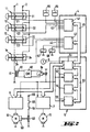
- Fig. 2 shows emergency stop switches 11 to 1n, which are connected to an electronic control system for a printing press.
- the latter consists of an input / output unit 4, a computing unit 5 and power units 6, 7, which are assigned to motors 61, 71.
- the power units essentially correspond to the main drive electronics 6 and the auxiliary drive electronics 7 (Fig. 1).
- Only two motors, namely the motor 61 of the main drive and a motor 71 of an auxiliary drive, have been shown, although printing presses can have significantly more motors.
- the design of the electronic control system in detail is possible in a variety of ways without departing from the scope of the invention.
- the input / output unit 4 comprises two input / output cards 41, 42, each of which has a multiplicity of inputs and outputs 43, 44.
- the input / output cards 41, 42 are connected to one another and to the input / output control card 51, which contains the monitoring circuit, among other things, of the computing unit via a bus system 45.
- the computer unit 5 further comprises a memory card 54 for storing data, for example data from the printing press and data from the jobs to be processed.
- a memory card 54 for storing data, for example data from the printing press and data from the jobs to be processed.
- non-volatile memories are provided on the memory card 54.
- the programs themselves were stored in read-only memories which are arranged on the cards of the computers 52 and 53.
- a bus system 55 connects the input / output controller 51, the computers 52, 53 and the memory card 54.
- the input / output unit 4 is provided for binary signals (for example, switches closed, switches open; relays attract, relays drop out), the outputs are digital Signals, which serve to control the power units 6, 7 and thus the motors 61, 71, via the input / output control 51.
- the input / output control 51 is also supplied with a signal corresponding to the machine speed by a tachometer 9.
- An electromagnet 63 for releasing the brake is supplied with operating voltage supplied at 66 via two contacts 64, 65 of two contactors 67, 68.
- the contacts 64, 65 are designed as working contacts, so that the brake is only released when both contacts 64, 65 are closed, which in turn is only the case when both contactors 67, 68 from the input / output unit 4 Voltage are supplied.
- the emergency switches of which only the emergency switches 11, 12, 13 and 1n are shown for the sake of clarity, can be provided with mushroom push buttons. However, other actuating devices, such as levers, tread strips and switches, which are actuated when protective guards are opened, can also be provided.
- Each of the emergency switches 11 to 1n has two contact pairs 21 to 2n, 31 to 3n working as a normally closed contact.
- the respective first contact pairs 21 to 2n are connected in series and connect a connection 1 provided with mains voltage to the primary winding 81 of a transformer.
- a rectifier 83 is connected to the secondary winding 82 of the transformer. There is thus a galvanic separation between the safety circuit formed by the series connection of the respective first contact pairs and the primary winding 81 and the subsequent circuits.
- the switching voltage is suitable for driving semiconductor circuits Reduced value, while the voltage supplying the safety circuit has a sufficiently large value to ensure a safe current flow despite the series connection of many contact pairs.
- Corresponding inputs of the power units 6, 7, the computer 52, 53 and the input / output controller 51 are connected to the safety circuit via a contactor 84.
- the respective second contact pairs 31 to 3n of the emergency switches 11 to 1n are connected to the inputs of the input / output unit 4 of the electronic control system.
- the printing press is nevertheless operated via the stopped by the respective first contacts 11 to 1n, the transformer 81, 82, the rectifier 83 and the contactor 84.
- the electromechanical braking device 60 is actuated.
- the contactors 67, 68 are de-energized, whereby the magnetic coil 63 is separated from the operating voltage supplied at 66 with the aid of the contacts 64, 65. 2, the control of the contactors 67, 68 takes place via the input / output unit 4, but two separate output circuits are provided for the contactors 67, 68 to ensure high security.
- switches 85, 86 can be connected to inputs of the input / output unit 4. These switches can be used to call up programs which result in a targeted shutdown of the printing press in accordance with the respective situation.
Landscapes
- Engineering & Computer Science (AREA)
- Mechanical Engineering (AREA)
- Inking, Control Or Cleaning Of Printing Machines (AREA)
Description
Die Erfindung betrifft ein Sicherheitssystem für eine Druckmaschine, die mit mindestens einer Antriebs- und Bremsvorrichtung und mit einer elektronischen Steuereinrichtung versehen ist.The invention relates to a security system for a printing press, which is provided with at least one drive and braking device and with an electronic control device.
Zur Erfüllung sicherheitstechnischer Auflagen sind verschiedene Sicherheitseinrichtungen an Druckmaschinen bekannt. So sind beispielsweise die verschiedenen Antriebe einer Druckmaschine mit Bremsen versehen, bei welchen die Bremskraft von Federn ausgeübt wird und zum Lösen bzw. Lüften der Bremsen Elektromagnete mit einer entsprechenden Spannung beaufschlagt werden.Various safety devices on printing presses are known to meet safety requirements. For example, the various drives of a printing press are provided with brakes, in which the braking force is exerted by springs and a corresponding voltage is applied to electromagnets to release or release the brakes.
Dabei werden bei bekannten Druckmaschinen die Bremsen sowohl als Betriebsbremsen als auch für den Notfall benutzt. Dieses führt zu einer unerwünschten Abnutzung der Bremsen.In known printing machines, the brakes are used both as service brakes and for emergencies. This leads to undesirable wear on the brakes.
Ferner sind an verschiedenen Stellen der Druckmaschine und gegebenenfalls auch in deren Umgebung Not-Aus-Schalter vorgesehen, mit deren Hilfe ein Anhalten der Druckmaschine vorgenommen werden kann. Damit ein Anhalten der Motoren ebenso wie ein Anlegen der Bremsen ohne elektrische Hilfsenergie möglich ist, sind bei bekannten Sicherheitseinrichtungen die Not-Aus-Schalter mit je einem Ruhekontakt versehen und in Reihe geschaltet.Furthermore, emergency stop switches are provided at various points on the printing press and possibly also in the vicinity thereof, with the aid of which the printing press can be stopped. So that the motors can be stopped as well as the brakes applied without electrical auxiliary energy, in known safety devices the emergency stop switches are each provided with a normally closed contact and connected in series.
In der DE-A 19 43 312 ist ein Antrieb für Druckwalzen in Druckmaschinen beschrieben, bei dem zum Erreichen einer hohen Positioniergenauigkeit im normalen Druckbetrieb ein die Druckwalze antreibender Elektromotor im Zusammenwirken mit einem elektrischen Steuerkreises für die Motordrehzahl und für die Abbremsung des Motors proportional zu einer jeweiligen Umdrehungszahl vorgesehen sind. Zur Abbremsung des Motors sind im Steuerkreis Umschaltelemente insbesondere Relais, angeordnet, die bewirken, daß der Motor als Generator arbeitet. Nachteilig hierbei ist, daß der Antrieb nebst Steuerkreis lediglich zum drehzahlproportionalen Beschleunigen und Verzögern von Druckwalzen einer Druckmaschine ausgelegt ist, und daß dieser Antrieb nicht geeignet ist, in Abhängigkeit von definierten Drehzahlverhältnissen im Rahmen eines Sicherheitssystems eine oder mehrere Bremsvorrichtungen zu betätigen, die eine schnelle Total- oder Teilabbremsung im Falle einer Not- oder Havariesituation bewirken.DE-A 19 43 312 describes a drive for printing rollers in printing presses in which an electric motor driving the printing roller in cooperation with in order to achieve a high positioning accuracy in normal printing operation an electrical control circuit for the engine speed and for braking the engine are provided in proportion to a respective number of revolutions. To slow down the motor, switching elements, in particular relays, are arranged in the control circuit, which cause the motor to work as a generator. The disadvantage here is that the drive, in addition to the control circuit, is only designed for speed-proportional acceleration and deceleration of printing rollers of a printing press, and that this drive is not suitable for actuating one or more braking devices as a function of defined speed ratios as part of a safety system, which provide a quick total - or cause partial braking in the event of an emergency or emergency situation.
In der deutschen Zeitschrift: Siemens-Energietechnik 1 (1979), Heft 4, Seiten 114-117, ist innerhalb einer elektronischen Antriebssteuerung und -überwachung eine Reglerüberwachung offenbart, bei der bei länger anstehender Abweichung zwischen Drehzahlsollwert und Drehzahlistwert ein Aus-Kommando gegeben wird. Das Aus-Kommando bewirkt eine sofortige Reglersperre mit verzögertem Abschalten eines Hauptschützes, welches einen Antriebsmotor stromlos schaltet.In the German magazine: Siemens-Energietechnik 1 (1979), number 4, pages 114-117, controller monitoring is disclosed within an electronic drive control and monitoring system, in which an off command is given if there is a long-standing deviation between the speed setpoint and actual speed value. The off command causes an immediate controller disable with delayed switching off of a main contactor, which switches a drive motor to de-energized.
Die Aufgabe der Erfindung besteht darin, ein Sicherheitssystem für eine Druckmaschine zu schaffen, das in Abhängigkeit von der Drehzahl der Antriebsvorrichtung und vom jeweiligen Betriebszustand der Druckmaschine eine definierte Abbremsung der bewegten Maschinenelemente ermöglicht.The object of the invention is to provide a safety system for a printing press which, depending on the speed of the drive device and the respective operating state of the printing press, enables a defined braking of the moving machine elements.
Die Aufgabe wird erfindungsgemäß mit einem System nach den Merkmalen des Anspruchs 1 gelöst.The object is achieved with a system according to the features of
Mit Hilfe der überwachungsschaltung, der Signale zu den Soll- und Istwerten der Drehzahl zugeführt werden, ist es möglich, laufend die Abweichungen zwischen Soll- und Istwert in jedem beliebigen Betriebszustand der Druckmaschine zu ermitteln und zum definierten Abbremsen der bewegten Maschinenelemente zu verwenden. Je nach Betriebszustand der Druckmaschine, aktueller Abweichung zwischen Soll- und Istwert der Drehzahl und der Betätigung eines der Not-Aus-Schalter, wird ein bestimmtes Programm zum Anhalten der Druckmaschine mit Hilfe eines der Rechner aus dem Speicher aufgerufen und abgearbeitet.With the aid of the monitoring circuit, to which signals for the setpoint and actual values of the speed are fed, it is possible to continuously determine the deviations between the setpoint and actual value in any operating state of the printing press and to use them for the defined braking of the moving machine elements. Depending on the operating state of the printing press, the current deviation between the setpoint and actual value of the speed and the actuation of one of the emergency stop switches, a specific program for stopping the printing press is called up and processed from the memory using one of the computers.
Dabei können je nach abgearbeitetem Programm die Maschinenelemente sowohl mit Hilfe der Ansteuerstufen und Leistungsstufen für den Elektromotor als auch mit Hilfe der elektromechanischen Bremsvorrichtung sicher abgebremst werden. Zum Aufrufen verschiedener Programme zum Anhalten der Druckmaschine können weitere Schalter mit Eingängen der elektronischen Steuereinrichtung verbunden sein.Depending on the program processed, the machine elements can be safely braked using the control stages and power levels for the electric motor as well as the electromechanical braking device. In order to call up various programs for stopping the printing press, further switches can be connected to inputs of the electronic control device.
Damit ist ein gezieltes Stillsitzen der Druckmaschine möglich - je nachdem, welcher dieser Schalter betätigt wurde. So kann es beispielsweise bei Betätigung eines Schalters im Bereich des Papieranlegers zweckmäßig sein, den Antrieb des Papieranlegers zwar sofort zu stoppen, jedoch den Hauptantrieb noch solange laufen zu lassen, bis die in der Maschine befindlichen Druckbögen die Maschine verlassen haben.This means that the press can be specifically stopped - depending on which of these switches has been pressed. For example, when a switch is actuated in the area of the paper feeder, it may be expedient to stop the drive of the paper feeder immediately, but to keep the main drive running until the drive in the Press sheets on the machine have left the machine.
Durch die erfindungsgemäßen Maßnahmen ist gewährleistet, daß die Steuerung des Bewegungsablaufs der Druckmaschine rein elektrisch erfolgt, so daß auch vorgegebene Verzögerungen möglich sind. Dabei werden die elektromechanischen Bremsvorrichtungen nur dann benötigt, wenn in der elektronischen Steuereinrichtung Fehler auftreten.The measures according to the invention ensure that the motion sequence of the printing press is controlled purely electrically, so that predetermined delays are also possible. The electromechanical braking devices are only required if errors occur in the electronic control device.
Dadurch, daß mehrere Notschalter jeweils parallel betätigbare erste und zweite Kontaktpaare aufweisen, daß die ersten Kontaktpaare in Reihe geschaltet sind und einen Sicherheitsstromkreis bilden und daß die zweiten Kontaktpaare einzeln mit Eingängen der elektronischen Steuereinrichtung verbunden sind, wird eine zusätzliche Sicherheit und die Möglichkeit erreicht, den jeweils ausgelösten oder fehlerhaften Not-Aus-Schalter zu lokalisieren. Dabei bleiben die grundsätzlichen Vorteile der Reihenschaltung sämtlicher Not-Aus-Schalter erhalten. Insbesondere kann eine Not-Aus-Abschaltung nicht deshalb unterbleiben, weil eine für die Weitergabe eines Not-Aus-Signals erforderliche Spannungsquelle nicht vorhanden ist.The fact that several emergency switches each have parallel operable first and second contact pairs, that the first contact pairs are connected in series and form a safety circuit, and that the second contact pairs are individually connected to inputs of the electronic control device, additional security and the possibility is achieved localize triggered or faulty emergency stop switches. The basic advantages of the series connection of all emergency stop switches are retained. In particular, an emergency stop cannot be omitted because there is no voltage source required for the transmission of an emergency stop signal.
Eine besondere Ausgestaltung dieses Merkmals besteht darin, daß der Sicherheitsstromkreis mit Netzwechselspannung gespeist ist und daß in Reihe mit den ersten Kontaktpaaren die Primärwicklung eines Transformators geschaltet ist, dessen Sekundärwicklung über einen Gleichrichter mit den Leistungsstufen der überwachungsschaltung und dem Rechner bzw. den Rechnern verbunden ist.A special embodiment of this feature is that the safety circuit is supplied with AC line voltage and that the primary winding of a transformer is connected in series with the first contact pairs, the secondary winding of which is connected via a rectifier to the power stages of the monitoring circuit and the computer or computers.
Durch diese Ausgestaltung ist eine Anpassung des Sicherheitsstromkreises an Halbleiterschaltungen möglich, ohne daß die den Sicherheitsstromkreis versorgende Spannung so niedrig ist, daß durch die Reihenschaltung vieler Kontakte ein sicherer Stromfluß in Frage gestellt ist.This configuration enables the safety circuit to be adapted to semiconductor circuits without the voltage supplying the safety circuit is so low that the series connection of many contacts jeopardizes safe current flow.
Die durch die zusätzlichen Kontaktpaare gewonnenen zusätzlichen Informationen können in verschiedenster Weise ausgewertet werden.The additional information obtained through the additional contact pairs can be evaluated in various ways.
Die Not-Aus-Schalter dienen dazu, im Falle einer Gefahr, die gesamte Maschine möglichst schnell zum Stehen zu bringen. Es sind jedoch Störungen möglich, welche lediglich ein Stillsetzen der Maschine in aufeinanderfolgenden Schritten erfordern.The emergency stop switches are used to bring the entire machine to a standstill as quickly as possible in the event of a danger. However, malfunctions are possible which only require the machine to be stopped in successive steps.
Zur weiteren Sicherheit ist gemäß einer Weiterbildung der Erfindung vorgesehen, daß die Betätigung der Bremsvorrichtung dadurch erfolgt, daß ein die Bremsvorrichtung entgegen einer Federkraft lösender Elektromagnet abgeschaltet wird.For further safety, it is provided according to a further development of the invention that the braking device is actuated by switching off an electromagnet that releases the braking device against a spring force.
Um auch dagegen geschützt zu sein, daß die Antriebsvorrichtung nicht zum Stillstand gebracht werden kann, wenn durch einen Fehler, beispielsweise in den Leistungsstufen, das höchstmögliche Drehmoment aufgebracht wird, ist die Bremsvorrichtung gemäß einer anderen Weiterbildung derart ausgelegt, daß die Druckmaschine auch dann zum Stillstand gebracht werden kann, wenn die Antriebsvorrichtung das höchstmögliche Drehmoment aufbringt.In order to also be protected against the fact that the drive device cannot be brought to a standstill if the highest possible torque is applied due to a fault, for example in the power stages, the braking device is designed in accordance with another development such that the printing press also comes to a standstill can be brought when the drive device applies the highest possible torque.
Bei einer Reihe von Defekten in der elektronischen Steuereinrichtung ist selbst bei einer unzulässig hohen Abwelchung zwischen Soll- und Istwert keine Betätigung der elektromechanischen Bremsvorrichtung erforderlich, solange die Leistungsstufen und gegebenenfalls mit ihnen verbundene Steuerstufen noch arbeiten. Für solche Fälle ist es vorgesehen, daß die Überwachungsschaltung vor der Betätigung Steuersignale zum Stillsetzen der Druckmaschine an die Leistungsstufen abgibt und erneut die Abweichung zwischen Soll -und Istwert der Drehzahl prüft.In the event of a number of defects in the electronic control device, no actuation of the electromechanical braking device is necessary, even with an impermissibly high discrepancy between the setpoint and actual value, as long as the power levels and any control stages connected to them still work. For such cases, it is provided that the monitoring circuit before the actuation control signals for stopping the printing press to the Outputs power levels and again checks the deviation between the setpoint and actual value of the speed.
Da die elektromechanische Bremsvorrichtung bei dem erfindungsgemäßen System sehr selten benutzt wird, könnte ein trotzdem auftretender Defekt an der Bremsvorrichtung nicht bemerkt werden. Es ist deshalb gemäß einer anderen Weiterbildung vorgesehen, daß durch Betätigung der Bremsvorrichtung, Steuerung der Antriebsvorrichtung auf das höchstmögliche Drehmoment und Auswertung des Drehzahl-Istwertes die Bremsvorrichtung überprüft wird. Dabei erfolgt die Überprüfung vorzugsweise nach dem Einschalten der elektronischen Steuereinrichtung.Since the electromechanical braking device is used very rarely in the system according to the invention, a defect in the braking device that nevertheless occurs could not be noticed. It is therefore provided according to another development that the braking device is checked by actuating the braking device, controlling the driving device for the highest possible torque and evaluating the actual speed value. The check is preferably carried out after switching on the electronic control device.
Ausführungsbeispiele der Erfindung sind in der Zeichnung anhand mehrerer Figuren dargestellt und in der nachfolgenden Beschreibung näher erläutert. Es zeigt:
- Fig. 1
- ein Blockschaltbild einer elektronischen Steuereinrichtung und
- Fig. 2
- ein Blockschaltbild einer weiteren elektronischen Steuereinrichtung mit einer Not-Aus-Einrichtung gemäß einer Weiterbildung der Erfindung.
- Fig. 1
- a block diagram of an electronic control device and
- Fig. 2
- a block diagram of another electronic control device with an emergency stop device according to a development of the invention.
Gleiche Teile sind in den Figuren mit gleichen Bezugszeichen versehen.Identical parts are provided with the same reference symbols in the figures.
Bei der in Figur 1 dargestellten elektronischen Steuereinrichtung werden ein Hauptantrieb 61 und verschiedene Hilfsantriebe, von denen lediglich zwei Hilfsantriebe 71, 72 dargestellt sind, von zwei Rechnern 52, 53 gesteuert. Die Rechner 52, 53 sind untereinander und mit einer Steuerelektronik 56 mit Hilfe eines Bus-Systems 55 verbunden.In the electronic control device shown in FIG. 1, a
Jeweils eine Hauptantriebselekronik 6 und eine Hilfsantriebselektronik 7 umfaßt neben Leistungsstufen auch zugehörige Ansteuerstufen, die bei einem praktisch ausgeführten erfindungsgemäßen System unter anderem mit Mikroprozessoren ausgerüstet sind.In each case, a
Die Steuerelektronik 56 hat vielseitige Aufgaben und umfaßt verschiedene Komponenten. Zum Verständnis der vorliegenden Erfindung ist jedoch lediglich die Erläuterung einer Überwachungsschaltung, welche Teil der Steuerelektronik 56 ist, erforderlich.
Der Überwachungsschaltung wird von einem Tachometer 9 der Istwert der Maschinengeschwindigkeit bzw. der Drehzahl des Hauptantriebes zugeführt. Ein Sollwert wird über das Bus-System 55 zugeleitet. Solange die Abweichung zwischen Soll- und Istwert in einem Bereich ist, der einer normalen Regelabweichung entspricht, werden von der Steuerelektronik zwei in Fig. 1 nicht dargestellte Schütze mit Strom versorgt, so daß die elektromechanische Hauptantriebsbremse gelöst ist.The monitoring circuit is supplied by a
Die Überwachungsschaltung in der Steuerelektronik 56 gibt bei Überschreiten einer zulässigen Abweichung zwischen Soll- und Istwert Signale zur Hauptantriebselektronik 6, um den Hauptantrieb 61 stillzusetzen. Diese Signale können eine Sperre der Zündimpulse der Leistungsstufen und/oder einer Ansteuerung der Leistungsstufen mit elektrischer Bremsung zur Folge haben.The monitoring circuit in the
Ist bei einem Defekt die Hauptantriebselektronik 6 funktionsfähig, so wird bei einem von der Überwachungsschaltung zur Stillsetzung des Hauptantriebs abgegebenen Signal die Maschinengeschwindigkeit durch die elektrische Bremsung schnell sinken, so daß weitere Maßnahmen nicht erforderlich sind.If the
Falls jedoch ein Defekt in der Hauptantriebselektronik 6 vorliegt, der zu einem Versagen der elektrischen Bremsung führt, so kann die Druckmaschine durch Betätigung der elektromechanischen Hauptantriebsbremse 60 stillgesetzt werden. In diesem Fall gibt die Überwachungsschaltung ein Signal zur Zündimpulssperre an die Hauptantriebselektronik 6, um zu vermeiden, daß der Hauptantrieb 61 weiterhin mit Strom versorgt wird - falls der Defekt in der Hauptantriebselektronik 6 dieses zuläßt.However, if there is a defect in the
Die Überwachungsschaltung überwacht ferner die Funktion der Rechner 52,53 und kann gegebenenfalls bei Ausfall eines Rechners sicherheitsrelevante Funktionen auf den anderen Rechner übertragen.The monitoring circuit also monitors the function of the
Außerdem überwacht die Überwachungsschaltung die Hilfsantriebselektronik 7, die Hilfsantriebe 71,72 sowie eine dem Hilfsantrieb 71 zugeordnete Bremsvorrichtung 70.In addition, the monitoring circuit monitors the auxiliary drive electronics 7, the
Wird ein Not-Aus-Signal von einer entsprechenden Einrichtung 57 ausgelöst, so wird es zu den Rechnern 52,53, zur Hauptantriebselektronik 6, zur Hilfsantriebselektronik 7 und zur Steuerelektronik 56 geleitet. Sofern kein Defekt in der elektronischen Steuereinrichtung vorliegt, wird die Druckmaschine wie oben beschrieben ohne Zuhilfenahme der elektromechanischen Bremsen angehalten. Erst wenn ein Defekt vorliegt, der dieses verhindert, wird die Druckmaschine mit Hilfe der elektromechanischen Bremsen stillgesetzt.If an emergency stop signal is triggered by a
Fig. 2 zeigt Not-Aus-Schalter 11 bis 1n, welche an ein elektronisches Steuersystem für eine Druckmaschine angeschlossen sind. Letzteres besteht aus einer Ein/Ausgabe-Einheit 4, einer Recheneinheit 5 und Leistungsteilen 6,7, welche Motoren 61,71 zugeordnet sind. Die Leistungsteile entsprechen im wesentlichen der Hauptantriebselektronik 6 und der Hilfsantriebselektronik 7 (Fig. 1). Der Übersichtlichkeit halber wurden lediglich zwei Motoren nämlich der Motor 61 des Hauptantriebes und ein Motor 71 eines Hilfsantriebes dargestellt, obwohl Druckmaschinen über wesentlich mehr Motore verfügen können. Die Auslegung des elektronischen Steuersystems im einzelnen ist in vielfältiger Weise möglich, ohne den Rahmen der Erfindung zu verlassen. Bei dem gezeigten Ausführungsbeispiel umfaßt die Ein-/Ausgabeeinheit 4 zwei Ein-/Ausgabekarten 41, 42, welche jeweils eine Vielzahl von Eingängen und Ausgängen 43, 44 aufweisen. Die Ein-/Ausgabekarten-41, 42 sind untereinander und mit der Ein-/Ausgabesteuerkarte 51, welche unter anderem die Überwachungsschaltung enthält, der Recheneinheit über ein Bussystem 45 verbunden.Fig. 2 shows emergency stop switches 11 to 1n, which are connected to an electronic control system for a printing press. The latter consists of an input / output unit 4, a computing unit 5 and
In der Recheneinheit sind zwei Rechner 52, 53 vorgesehen, welche an sich verschiedene Aufgaben erfüllen, jedoch derart programmiert sind, daß bei Ausfall eines der Rechner 52, 53 der andere Rechner Aufgaben des ausgefallenen Rechners, insbesondere sicherheitsrelevante Steuerungen, übernimmt. Die Rechnereinheit 5 umfaßt ferner eine Speicherkarte 54 zur Speicherung von Daten, beispielsweise Daten der Druckmaschine und Daten der zu bearbeitenden Aufträge. Dazu sind auf der Speicherkarte 54 nichtflüchtige Speicher vorgesehen. Bei einem praktisch ausgeführten elektronischen Steuersystem wurden die Programme selbst in Nur-Lese-Speichern abgelegt, welche auf den Karten der Rechner 52 und 53 angeordnet sind. Es sind jedoch auch andere Konfigurationen zur Speicherung der Programme Rahmen der Erfindung möglich. Ein Bussystem 55 verbindet die Ein-/Ausgabesteuerung 51, die Rechner 52, 53 und die Speicherkarte 54.Two
Wahrend bei dem dargestellten elektronischen Steuerungssystem die Ein/Ausgabe-Einheit 4 für binäre Signale vorgesehen ist (beispielsweise Schalter geschlossen, Schalter offen; Relais anziehen, Relais abfallen), erfolgt die Ausgabe von digitalen Signalen, welche zur Steuerung der Leistungsteile 6,7 und damit der Motoren 61,71 dienen, über die Ein/Ausgabe-Steuerung 51. Der Ein/Ausgabe-Steuerung 51 wird ferner von einem Tachometer 9 ein der Maschinengeschwindigkeit entsprechendes Signal zugeführt.While in the electronic control system shown, the input / output unit 4 is provided for binary signals (for example, switches closed, switches open; relays attract, relays drop out), the outputs are digital Signals, which serve to control the
Von mehreren den Motoren zugeordneten Bremseinrichtungen ist lediglich die dem Hauptantrieb zugeordnete elektromechanische Bremseinrichtung schematisch dargestellt. Dabei wird ein Elektromagnet 63 zum Lüften der Bremse über zwei Kontakte 64,65 zweier Schütze 67,68 mit bei 66 zugeführter Betriebsspannung versorgt. Die Kontakte 64,65 sind als Arbeitskontakte ausgelegt, so daß die Bremse nur dann gelüftet wird, wenn beide Kontakte 64,65 geschlossen sind, was wiederum nur der Fall ist, wenn beide Schütze 67,68 von der Ein/Ausgabe-Einheit 4 mit Spannung versorgt werden.Of several brake devices assigned to the motors, only the electromechanical brake device assigned to the main drive is shown schematically. An
Die Notschalter, von denen der Übersichtlichkeit halber lediglich die Notschalter 11,12,13 und 1n dargestellt sind, können mit Pilzdruckknöpfen versehen sein. Es können jedoch auch andere Betätigungsvorrichtungen, wie beispielsweise Hebel, Trittleisten und Schalter, die beim Öffnen von Schutzgittern betätigt werden, vorgesehen werden. Jeder der Notschalter 11 bis 1n weist zwei als Ruhekontakt arbeitende Kontaktpaare 21 bis 2n, 31 bis 3n auf. Die jeweils ersten Kontaktpaare 21 bis 2n sind in Reihe geschaltet und verbinden einen mit Netzspannung versehenen Anschluß 1 mit der Primärwicklung 81 eines Transformators.The emergency switches, of which only the emergency switches 11, 12, 13 and 1n are shown for the sake of clarity, can be provided with mushroom push buttons. However, other actuating devices, such as levers, tread strips and switches, which are actuated when protective guards are opened, can also be provided. Each of the emergency switches 11 to 1n has two contact pairs 21 to 2n, 31 to 3n working as a normally closed contact. The respective first contact pairs 21 to 2n are connected in series and connect a
An die Sekundärwicklung 82 des Transformators ist ein Gleichrichter 83 angeschlossen. Es wird somit eine galvanische Trennung zwischen dem durch die Reihenschaltung der jeweils ersten Kontaktpaare und der Primärwicklung 81 gebildeten Sicherheitsstromkreis und den nachfolgenden Schaltungen erzielt. Außerdem wird die Schaltspannung auf einen zur Ansteuerung von Halbleiterschaltungen geeigneten Wert herabgesetzt, während die den Sicherheitsstromkreis speisende Spannung einen genügend großen Wert aufweist, um trotz der Reihenschaltung vieler Kontaktpaare einen sicheren Stromfluß zu gewährleisten. Über ein Schütz 84 sind entsprechende Eingänge der Leistungsteile 6,7, der Rechner 52,53 und der Ein/Ausgabe-Steuerung 51 mit dem Sicherheitskreis verbunden.A
Die jeweils zweiten Kontaktpaare 31 bis 3n der Notschalter 11 bis 1n sind an Eingange der Ein/Ausgabe-Einheit 4 des elektronischen Steuersystems angeschlossen.The respective second contact pairs 31 to 3n of the emergency switches 11 to 1n are connected to the inputs of the input / output unit 4 of the electronic control system.
Bei Betätigung eines der Not-Aus-Schalter 11 bis 1n wird der Sicherheitsstromkreis unterbrochen, so daß die Primärwicklung 81 nicht mehr über den Anschluß 1 mit Netzspannung versorgt wird. Daraufhin wird auch die Sekundärspannung sowie die Ausgangsspannung des Gleichrichters 83 zu 0, und das Schütz 84 fällt ab. Diese Vorgänge benötigen eine gewisse Zeit, während - ausgelöst vom öffnen des zweiten Kontaktes des betätigten Not-Aus-Schalters - in der elektronischen Steuereinrichtung 5 bereits entsprechende Programmschritte zum Stillsetzen der Druckmaschine eingeleitet werden.When one of the emergency stop switches 11 to 1n is actuated, the safety circuit is interrupted, so that the primary winding 81 is no longer supplied with mains voltage via the
Sollten in der Ein/Ausgabe-Einheit 4 oder in der Recheneinheit 5 Defekte vorliegen, welche eine wirksame Weiterleitung der von den jeweils zweiten Kontakten 31 bis 3n der Not-Aus-Schalter 11 bis 1n abgegebenen Signale verhindern, so wird die Druckmaschine trotzdem über den von den jeweils ersten Kontakten 11 bis 1n, dem Transformator 81,82, dem Gleichrichter 83 und dem Schütz 84 gebildeten Sicherheitskreis angehalten.If there are defects in the input / output unit 4 or in the arithmetic unit 5, which prevent effective transmission of the signals emitted by the respective
Erst wenn die elektronische Steuereinrichtung nicht in der Lage ist, die Druckmaschine durch elektrische Bremsung anzuhalten, wird - wie im Zusammenhang mit Fig. 1 beschrieben - die elektromechanische Bremsvorrichtung 60 betätigt. Dazu werden die Schütze 67,68 stromlos geschaltet, wodurch die Magnetspule 63 mit Hilfe der Kontakte 64,65 von der bei 66 zugeführten Betriebsspannung getrennt wird. Bei der Einrichtung nach Fig. 2 erfolgt die Steuerung der Schütze 67,68 zwar über die Ein/Ausgabe-Einheit 4, es sind jedoch zur Gewährleistung einer hohen Sicherheit zwei getrennte Ausgangskreise für die Schütze 67,68 vorgesehen.Only when the electronic control device is not able to stop the printing press by means of electrical braking, is it - as described in connection with FIG. 1 - The
Auch wenn keine ausgesprochene Notsituation vorliegt, kann ein außerplanmäßiges Anhalten der Druckmaschine erwünscht sein. Dazu können weitere Schalter 85,86 mit Eingängen der Ein/Ausgabe-Einheit 4 verbunden sein. Durch diese Schalter können Programme abgerufen werden, welche ein der jeweiligen Situation entsprechendes, gezieltes Stillsetzen der Druckmaschine zur Folge haben.Even if there is no pronounced emergency situation, an unscheduled stop of the printing press may be desirable. For this purpose, further switches 85, 86 can be connected to inputs of the input / output unit 4. These switches can be used to call up programs which result in a targeted shutdown of the printing press in accordance with the respective situation.
Claims (11)
- Safety system for a printing machine,- comprising a drive device for the moved machine elements, which is connected to a control device to which signals for the desired value and actual value of the rotational speed of the drive device can be fed and which is connected to actuation stages and power stages for at least one electric motor, characterized- in that a monitoring circuit (51) is provided which, in the case of unacceptably high deviation between the desired value and actual value, outputs a signal for the defined braking of the moved machine elements to the actuation stages and an electromechanical braking device (60),- in that the monitoring circuit (51) contains two redundantly acting computers (52, 53) and a memory (54) for programs for braking the moved machine elements,
the monitoring circuit (51) being connected to the computers (52, 53) and the memory (54) via a bus system (55) and being connected via a further bus system (45) to an input/output unit (4) for signals from emergency off switches (11, 12, 13, 1n, 85, 86) arranged in the printing machine and for signals for actuating the electromechanical braking device (60),- in that the emergency off switches (11, 12, 13, 1n) each have first and second normally closed contacts (21, 22, 23, 2n; 31, 32, 33, 3n), the first normally closed contacts (21, 22, 23, 2n) being connected in a series circuit by technical signalling means to separate inputs of the monitoring circuit (51), to the computers (52, 53) and the actuation stages for the power stages (6, 7),
and the second normally closed contacts (31, 32, 33, 3n) are connected to separate inputs (43, 44) of the input/output unit (4). - Safety system according to Claim 1, characterized in that the activation of the braking device (60) takes place in that an electromagnet (63) which releases the braking device (60) counter to a spring force is switched off.
- Safety system according to Claim 2, characterized in that, in series with the electromagnets (63), two pairs of contacts (64, 65) of two contactors (67, 68) are connected in series, and in that the contactors (67, 68) can be actuated via separate output circuits (42) of the electronic control device.
- Safety system according to one of the preceding claims, characterized in that the braking device (60) is configured in such a way that the printing machine can be brought to a standstill even when the drive device (61) is applying the maximum torque.
- Safety system according to one of the preceding claims, characterized in that, before the activation, the monitoring circuit (51) transmits to the power stages (6, 7) control signals for bringing the printing machine to a standstill and tests the deviation between the desired value and actual value of the rotational speed again.
- Safety system according to one of the preceding claims, characterized in that the braking device (60) is checked by activating the braking device (60), controlling the drive device (61) to the maximum torque and evaluating the actual value of the rotational speed.
- Safety system according to Claim 6, characterized in that the checking takes place after the electronic control device is switched on.
- Safety system according to one of the preceding claims, characterized in that, in an electronic control device having two computers (52, 53), the monitoring circuit (51) compares those functions of the computers (52, 53) which are relevant for safety with one another and in the event of one of the computers (52) failing assigns the control of the drive device (61) to the other computer (53).
- Safety system according to one of the preceding claims, characterized in that further braking devices which are assigned to further drive devices (71) (auxiliary drives) can be controlled by the monitoring circuit (51).
- Safety system according to Claim 1, characterized in that the first pairs of contacts (21 to 2n) are connected in series and form a safety circuit, and in that the second pairs of contacts (31 to 3n) are individually connected to inputs of the input/output unit (4).
- Safety system according to Claim 10, characterized in that the safety circuit is fed with alternating mains voltage,
and in that the primary winding (81) of a transformer is connected in series with the first pairs of contacts (21 to 2n), the secondary winding (82) of which transformer is connected via a rectifier (83) to the power stages (6, 7), the monitoring circuit (51) and the computer or computers (52, 53).
Applications Claiming Priority (2)
| Application Number | Priority Date | Filing Date | Title |
|---|---|---|---|
| DE3614979A DE3614979C3 (en) | 1986-05-02 | 1986-05-02 | Security system for a printing press |
| DE3614979 | 1986-05-02 |
Publications (4)
| Publication Number | Publication Date |
|---|---|
| EP0243728A2 EP0243728A2 (en) | 1987-11-04 |
| EP0243728A3 EP0243728A3 (en) | 1989-08-30 |
| EP0243728B1 EP0243728B1 (en) | 1992-03-18 |
| EP0243728B2 true EP0243728B2 (en) | 1995-12-13 |
Family
ID=6300079
Family Applications (1)
| Application Number | Title | Priority Date | Filing Date |
|---|---|---|---|
| EP87104965A Expired - Lifetime EP0243728B2 (en) | 1986-05-02 | 1987-04-03 | Safety system for a printing machine |
Country Status (5)
| Country | Link |
|---|---|
| US (1) | US4951567A (en) |
| EP (1) | EP0243728B2 (en) |
| JP (1) | JPS62271745A (en) |
| CA (1) | CA1286021C (en) |
| DE (2) | DE3614979C3 (en) |
Families Citing this family (42)
| Publication number | Priority date | Publication date | Assignee | Title |
|---|---|---|---|---|
| JPS63137846A (en) * | 1986-12-01 | 1988-06-09 | Komori Printing Mach Co Ltd | Control apparatus of printing press |
| DE3811046C2 (en) * | 1988-03-31 | 1994-05-26 | Heidelberger Druckmasch Ag | Method and device for determining the gear ratio on a printing press |
| DE3843966A1 (en) * | 1988-12-24 | 1990-06-28 | Heidelberger Druckmasch Ag | DEVICE FOR CONNECTING ADDITIONAL DEVICES |
| JPH03177257A (en) * | 1989-12-04 | 1991-08-01 | Tokyo Kikai Seisakusho Ltd | Web paper guiding device |
| DE4013106C1 (en) * | 1990-04-25 | 1991-12-12 | Man Roland Druckmaschinen Ag, 6050 Offenbach, De | |
| DE4106901C2 (en) * | 1991-03-05 | 1994-05-26 | Kotterer Grafotec | Method and device for monitoring a web |
| DE4202722B4 (en) * | 1992-01-31 | 2005-09-29 | Heidelberger Druckmaschinen Ag | Safety device for controls or controls of drive units of a printing machine |
| DE4232559C2 (en) * | 1992-09-29 | 1994-07-28 | Roland Man Druckmasch | Device and method for registering coupling of a web-fed rotary printing press |
| DE4241807A1 (en) * | 1992-12-11 | 1994-06-16 | Heidelberger Druckmasch Ag | Drive for a printing press |
| DE4327848C2 (en) * | 1993-08-19 | 1996-06-05 | Roland Man Druckmasch | Control device for a printing press |
| DE4327972C1 (en) * | 1993-08-19 | 1994-10-20 | Herlan & Co Maschf | Method for controlling the stopping of a printing unit of a tube or can printing machine |
| DE4413047C2 (en) * | 1994-04-15 | 1996-04-18 | Roland Man Druckmasch | Method and device for brake monitoring the DC motor of a printing press |
| US6644184B1 (en) | 1995-02-09 | 2003-11-11 | Man Roland Druckmaschinen Ag | Offset printing machine |
| DE4430693B4 (en) * | 1994-08-30 | 2005-12-22 | Man Roland Druckmaschinen Ag | Drives for a web-fed rotary offset printing machine |
| DE19504069A1 (en) * | 1995-02-08 | 1996-08-22 | Roland Man Druckmasch | Method and device for braking an electrical main drive of a printing press |
| US5901647A (en) * | 1995-03-18 | 1999-05-11 | Koenig & Bauer-Albert Aktiengesellschaft | Process for driving equipment e.g. a folding device for a rotary press |
| DE19525169C2 (en) * | 1995-03-18 | 2000-02-03 | Koenig & Bauer Ag | Method for driving a folder |
| FR2734513B1 (en) * | 1995-05-22 | 1997-08-14 | Heidelberg Harris Sa | METHOD FOR DETECTING DISTURBANCES IN THE TRANSPORT OF A CONTINUOUS PAPER TABLECLOTH IN A PRINTING MACHINE |
| DE19520918C2 (en) * | 1995-06-08 | 1998-02-26 | Roland Man Druckmasch | Control for a printing press |
| DE19520919C2 (en) * | 1995-06-08 | 1998-02-26 | Roland Man Druckmasch | Control for a printing press |
| DE19520642C1 (en) * | 1995-06-09 | 1996-12-05 | Roland Man Druckmasch | Method for controlling a multi-motor drive of a printing press and corresponding control |
| DE19529430C2 (en) * | 1995-07-06 | 2000-07-13 | Baumueller Nuernberg Gmbh | Electric drive system for the adjustment of several rotating and / or swiveling functional parts |
| DE19536918C1 (en) * | 1995-10-04 | 1997-01-30 | Roland Man Druckmasch | Monitoring device for driving a printing press |
| US5732637A (en) * | 1995-10-24 | 1998-03-31 | Virco Mfg. Corporation | Lightweight plastic furniture |
| DE19643252C2 (en) * | 1996-10-19 | 1999-05-20 | Roland Man Druckmasch | Control for the operation of a printing press |
| JP3037650B2 (en) * | 1997-10-29 | 2000-04-24 | 株式会社東京機械製作所 | Drive unit for printing unit of rotary press |
| JP4041569B2 (en) * | 1997-12-26 | 2008-01-30 | クラリオン株式会社 | Disc player |
| DE29813975U1 (en) * | 1998-08-05 | 1998-10-08 | MAN Roland Druckmaschinen AG, 63075 Offenbach | Control computer for a printing press |
| DE20000919U1 (en) | 2000-01-20 | 2000-03-09 | MAN Roland Druckmaschinen AG, 63075 Offenbach | Monitoring device for a printing press |
| DE10141590C5 (en) | 2000-09-19 | 2018-05-03 | Heidelberger Druckmaschinen Ag | Device for controlling a printing machine |
| DE10120238B4 (en) * | 2001-04-19 | 2006-07-06 | Dr. Johannes Heidenhain Gmbh | actuator |
| DE20117222U1 (en) | 2001-10-24 | 2002-01-17 | Siemens AG, 80333 München | Production machine with a drive train consisting of drive sections |
| DE10227241A1 (en) * | 2002-06-19 | 2004-01-15 | Koenig & Bauer Ag | Control for rotary printing machines |
| DE10254608B4 (en) * | 2002-11-22 | 2010-12-02 | Siemens Ag | drive system |
| DE10319064A1 (en) * | 2003-04-25 | 2004-11-11 | Focke & Co.(Gmbh & Co. Kg) | Method and device for controlling a manufacturing unit |
| US7453677B2 (en) * | 2004-10-06 | 2008-11-18 | Teknic, Inc. | Power and safety control hub |
| DE102006053027A1 (en) * | 2006-11-10 | 2008-05-15 | Man Roland Druckmaschinen Ag | Printing machine i.e. web-fed rotary press, operating method, involves directly operating drive functions depending on changed safety functions in drive controllers of driven assemblies during occurrence of safety-relevant results |
| FR2910374B1 (en) * | 2006-12-22 | 2009-04-03 | Goss Int Montataire Sa | METHOD FOR CONTROLLING A ROTARY PRESS AND ROTATING PRESS |
| FR2910373B1 (en) * | 2006-12-22 | 2009-04-03 | Goss Int Montataire Sa | METHOD FOR CONTROLLING A ROTARY PRESS AND ROTATING PRESS |
| DE102007033432A1 (en) * | 2007-07-18 | 2009-01-22 | Heidelberger Druckmaschinen Ag | Printing machine with electric crush protection |
| DE102016209989A1 (en) * | 2016-06-07 | 2017-12-07 | Heidelberger Druckmaschinen Ag | Printing machine with individually driven cylinders |
| ES2820648T3 (en) * | 2017-09-29 | 2021-04-21 | Siemens Energy Global Gmbh & Co Kg | Winding procedure and device of a paper making machine |
Family Cites Families (9)
| Publication number | Priority date | Publication date | Assignee | Title |
|---|---|---|---|---|
| DE378616C (en) * | 1922-05-11 | 1923-07-21 | Walter Nowak | Device for stopping and braking electrically driven printing machines or other machines when a paper web or a rope-like strand of goods tears |
| DE1110658B (en) * | 1959-06-03 | 1961-07-13 | Planeta Veb Druckmasch Werke | Circuit arrangement on sheet-fed rotary offset printing machines |
| DE1098258B (en) * | 1959-10-14 | 1961-01-26 | Maschf Augsburg Nuernberg Ag | Safety device for monitoring the speed of a shaft |
| US3183423A (en) * | 1961-09-22 | 1965-05-11 | Square D Co | Limit control for motors |
| US3296512A (en) * | 1963-10-23 | 1967-01-03 | Westinghouse Electric Corp | Controlled braking system for load lifting apparatus |
| GB1276843A (en) * | 1968-08-28 | 1972-06-07 | Antoma Hairdressing Company Lt | Improvements in or relating to uprintin machines |
| DD226708B1 (en) * | 1984-09-03 | 1989-07-05 | Medizin Labortechnik Veb K | CIRCUIT ARRANGEMENT FOR THE RELIABILITY MONITORING OF SPEED PULSES |
| DE3447090A1 (en) * | 1984-12-22 | 1986-06-26 | Heidelberger Druckmaschinen Ag, 6900 Heidelberg | METHOD AND DEVICE FOR BRAKE CONTROL OF A MOTION MONITORED AND CONTROLLED DRIVE MOTOR IN A PRINTING MACHINE |
| US4643091A (en) * | 1985-11-25 | 1987-02-17 | Ncr Corporation | Electromagnetic clutch-brake positioning assembly |
-
1986
- 1986-05-02 DE DE3614979A patent/DE3614979C3/en not_active Expired - Fee Related
-
1987
- 1987-03-11 CA CA000531408A patent/CA1286021C/en not_active Expired - Lifetime
- 1987-04-03 DE DE8787104965T patent/DE3777437D1/en not_active Expired - Lifetime
- 1987-04-03 EP EP87104965A patent/EP0243728B2/en not_active Expired - Lifetime
- 1987-05-01 JP JP62106486A patent/JPS62271745A/en active Pending
-
1989
- 1989-07-07 US US07/376,937 patent/US4951567A/en not_active Expired - Lifetime
Also Published As
| Publication number | Publication date |
|---|---|
| US4951567A (en) | 1990-08-28 |
| JPS62271745A (en) | 1987-11-26 |
| EP0243728A2 (en) | 1987-11-04 |
| DE3777437D1 (en) | 1992-04-23 |
| DE3614979C2 (en) | 1994-02-10 |
| DE3614979C3 (en) | 1999-12-16 |
| DE3614979A1 (en) | 1987-11-05 |
| EP0243728B1 (en) | 1992-03-18 |
| CA1286021C (en) | 1991-07-09 |
| EP0243728A3 (en) | 1989-08-30 |
Similar Documents
| Publication | Publication Date | Title |
|---|---|---|
| EP0243728B2 (en) | Safety system for a printing machine | |
| DE4334260C2 (en) | Control device for a vehicle with an anti-lock braking device and a power steering device | |
| EP0187247B1 (en) | Method and device for controlling the braking of a drive motor in a printing press | |
| DE4107330C2 (en) | Electronic control device for a vehicle | |
| EP0780276A2 (en) | Braking device for a vehicle | |
| DE3723205A1 (en) | AUXILIARY POWER STEERING, ESPECIALLY FOR MOTOR VEHICLES | |
| EP1031420A1 (en) | Device for the monitoring of safety-relevant processes in machines | |
| EP3197812A1 (en) | Elevator brake | |
| DE19509150A1 (en) | Method of controlling vehicle brake units | |
| EP0052759A2 (en) | Device by an electronic signal box for the power supply and telecontrol of switch drives | |
| DE3428215A1 (en) | Arrangement for monitoring a stored-program control device | |
| EP0153900A2 (en) | Control and protection of servoswitching of points with a telecontrol device or a local control device | |
| EP0830998A1 (en) | Electrical brake system and process for carrying on an electrical brake system | |
| WO2005021347A1 (en) | Emergency braking device and brake system for a rail vehicle, and method for ensuring an emergency braking function in rail vehicles | |
| DE1920297C3 (en) | Safety device for a vehicle door with means for locking and releasing the door operation | |
| DE4327848A1 (en) | Control device for a printing press | |
| EP2175552A1 (en) | Method for operating a drive device and drive device for implementing the method | |
| DE69212373T2 (en) | Regulation of the clutch brake drive of a press | |
| DE19732764B4 (en) | Transmission device for control signals, especially in vehicles | |
| DE4413047A1 (en) | Method and device for brake monitoring the DC motor of a printing press | |
| EP3414637B1 (en) | Safety switching apparatus | |
| DE3919558C2 (en) | ||
| EP0243620A1 (en) | Actuator for a differential lock control device | |
| EP0726643A1 (en) | Method and device for braking the electric main drive of a printing machine | |
| DE102019112713A1 (en) | SWITCH ARRANGEMENT AND PROCEDURE FOR SAFE OPERATION OF A SWITCH ARRANGEMENT |
Legal Events
| Date | Code | Title | Description |
|---|---|---|---|
| PUAI | Public reference made under article 153(3) epc to a published international application that has entered the european phase |
Free format text: ORIGINAL CODE: 0009012 |
|
| 17P | Request for examination filed |
Effective date: 19870403 |
|
| AK | Designated contracting states |
Kind code of ref document: A2 Designated state(s): CH DE FR GB IT LI NL SE |
|
| PUAL | Search report despatched |
Free format text: ORIGINAL CODE: 0009013 |
|
| AK | Designated contracting states |
Kind code of ref document: A3 Designated state(s): CH DE FR GB IT LI NL SE |
|
| 17Q | First examination report despatched |
Effective date: 19910313 |
|
| GRAA | (expected) grant |
Free format text: ORIGINAL CODE: 0009210 |
|
| AK | Designated contracting states |
Kind code of ref document: B1 Designated state(s): CH DE FR GB IT LI NL SE |
|
| PGFP | Annual fee paid to national office [announced via postgrant information from national office to epo] |
Ref country code: SE Payment date: 19920414 Year of fee payment: 6 |
|
| REF | Corresponds to: |
Ref document number: 3777437 Country of ref document: DE Date of ref document: 19920423 |
|
| PGFP | Annual fee paid to national office [announced via postgrant information from national office to epo] |
Ref country code: NL Payment date: 19920430 Year of fee payment: 6 |
|
| ITF | It: translation for a ep patent filed | ||
| GBT | Gb: translation of ep patent filed (gb section 77(6)(a)/1977) | ||
| ET | Fr: translation filed | ||
| PLBI | Opposition filed |
Free format text: ORIGINAL CODE: 0009260 |
|
| 26 | Opposition filed |
Opponent name: MAN ROLAND DRUCKMASCHINEN AG Effective date: 19921216 |
|
| NLR1 | Nl: opposition has been filed with the epo |
Opponent name: MAN ROLAND DRUCKMASCHINEN AG |
|
| PG25 | Lapsed in a contracting state [announced via postgrant information from national office to epo] |
Ref country code: SE Effective date: 19930404 |
|
| PG25 | Lapsed in a contracting state [announced via postgrant information from national office to epo] |
Ref country code: NL Effective date: 19931101 |
|
| NLV4 | Nl: lapsed or anulled due to non-payment of the annual fee | ||
| EUG | Se: european patent has lapsed |
Ref document number: 87104965.6 Effective date: 19931110 |
|
| PUAH | Patent maintained in amended form |
Free format text: ORIGINAL CODE: 0009272 |
|
| STAA | Information on the status of an ep patent application or granted ep patent |
Free format text: STATUS: PATENT MAINTAINED AS AMENDED |
|
| 27A | Patent maintained in amended form |
Effective date: 19951213 |
|
| AK | Designated contracting states |
Kind code of ref document: B2 Designated state(s): CH DE FR GB IT LI NL SE |
|
| REG | Reference to a national code |
Ref country code: CH Ref legal event code: AEN Free format text: AUFRECHTERHALTUNG DES PATENTES IN GEAENDERTER FORM |
|
| ET3 | Fr: translation filed ** decision concerning opposition | ||
| GBTA | Gb: translation of amended ep patent filed (gb section 77(6)(b)/1977) |
Effective date: 19960313 |
|
| PGFP | Annual fee paid to national office [announced via postgrant information from national office to epo] |
Ref country code: CH Payment date: 19980518 Year of fee payment: 12 |
|
| PG25 | Lapsed in a contracting state [announced via postgrant information from national office to epo] |
Ref country code: LI Free format text: LAPSE BECAUSE OF NON-PAYMENT OF DUE FEES Effective date: 19990430 Ref country code: CH Free format text: LAPSE BECAUSE OF NON-PAYMENT OF DUE FEES Effective date: 19990430 |
|
| REG | Reference to a national code |
Ref country code: CH Ref legal event code: PL |
|
| REG | Reference to a national code |
Ref country code: GB Ref legal event code: IF02 |
|
| PG25 | Lapsed in a contracting state [announced via postgrant information from national office to epo] |
Ref country code: IT Free format text: LAPSE BECAUSE OF NON-PAYMENT OF DUE FEES;WARNING: LAPSES OF ITALIAN PATENTS WITH EFFECTIVE DATE BEFORE 2007 MAY HAVE OCCURRED AT ANY TIME BEFORE 2007. THE CORRECT EFFECTIVE DATE MAY BE DIFFERENT FROM THE ONE RECORDED. Effective date: 20050403 |
|
| PGFP | Annual fee paid to national office [announced via postgrant information from national office to epo] |
Ref country code: FR Payment date: 20050419 Year of fee payment: 19 |
|
| PGFP | Annual fee paid to national office [announced via postgrant information from national office to epo] |
Ref country code: DE Payment date: 20050427 Year of fee payment: 19 |
|
| PGFP | Annual fee paid to national office [announced via postgrant information from national office to epo] |
Ref country code: GB Payment date: 20060410 Year of fee payment: 20 |
|
| PG25 | Lapsed in a contracting state [announced via postgrant information from national office to epo] |
Ref country code: DE Free format text: LAPSE BECAUSE OF NON-PAYMENT OF DUE FEES Effective date: 20061101 |
|
| REG | Reference to a national code |
Ref country code: FR Ref legal event code: ST Effective date: 20061230 |
|
| PG25 | Lapsed in a contracting state [announced via postgrant information from national office to epo] |
Ref country code: GB Free format text: LAPSE BECAUSE OF EXPIRATION OF PROTECTION Effective date: 20070402 |
|
| REG | Reference to a national code |
Ref country code: GB Ref legal event code: PE20 |
|
| PG25 | Lapsed in a contracting state [announced via postgrant information from national office to epo] |
Ref country code: FR Free format text: LAPSE BECAUSE OF NON-PAYMENT OF DUE FEES Effective date: 20060502 |