EP0243679B1 - Schreibfederregistrierapparat mit verbesserter Genauigkeit - Google Patents
Schreibfederregistrierapparat mit verbesserter Genauigkeit Download PDFInfo
- Publication number
- EP0243679B1 EP0243679B1 EP87104426A EP87104426A EP0243679B1 EP 0243679 B1 EP0243679 B1 EP 0243679B1 EP 87104426 A EP87104426 A EP 87104426A EP 87104426 A EP87104426 A EP 87104426A EP 0243679 B1 EP0243679 B1 EP 0243679B1
- Authority
- EP
- European Patent Office
- Prior art keywords
- pen
- recording
- recording paper
- recorder
- detecting
- Prior art date
- Legal status (The legal status is an assumption and is not a legal conclusion. Google has not performed a legal analysis and makes no representation as to the accuracy of the status listed.)
- Expired - Lifetime
Links
- 238000001514 detection method Methods 0.000 claims description 9
- 230000003287 optical effect Effects 0.000 claims description 6
- 230000004044 response Effects 0.000 claims description 5
- 230000006870 function Effects 0.000 description 3
- 238000010586 diagram Methods 0.000 description 2
- 238000000034 method Methods 0.000 description 2
- 230000008569 process Effects 0.000 description 2
- 230000008859 change Effects 0.000 description 1
- 238000006243 chemical reaction Methods 0.000 description 1
- 238000010276 construction Methods 0.000 description 1
- 230000000593 degrading effect Effects 0.000 description 1
- 230000001419 dependent effect Effects 0.000 description 1
- 230000006872 improvement Effects 0.000 description 1
- 229920003023 plastic Polymers 0.000 description 1
- 238000004904 shortening Methods 0.000 description 1
Images


Classifications
-
- G—PHYSICS
- G01—MEASURING; TESTING
- G01D—MEASURING NOT SPECIALLY ADAPTED FOR A SPECIFIC VARIABLE; ARRANGEMENTS FOR MEASURING TWO OR MORE VARIABLES NOT COVERED IN A SINGLE OTHER SUBCLASS; TARIFF METERING APPARATUS; MEASURING OR TESTING NOT OTHERWISE PROVIDED FOR
- G01D15/00—Component parts of recorders for measuring arrangements not specially adapted for a specific variable
- G01D15/24—Drives for recording elements and surfaces not covered by G01D5/00
-
- G—PHYSICS
- G01—MEASURING; TESTING
- G01D—MEASURING NOT SPECIALLY ADAPTED FOR A SPECIFIC VARIABLE; ARRANGEMENTS FOR MEASURING TWO OR MORE VARIABLES NOT COVERED IN A SINGLE OTHER SUBCLASS; TARIFF METERING APPARATUS; MEASURING OR TESTING NOT OTHERWISE PROVIDED FOR
- G01D9/00—Recording measured values
- G01D9/02—Producing one or more recordings of the values of a single variable
Definitions
- the present invention relates to an improvement in the recording accuracy and reliability of a pen recorder of the type mentioned in the pre-characterizing portion of claim 1.
- a pen when a pen is to be moved to a recording position corresponding to an analog input signal, an amount of motion of the pen is detected as an angular interval by a potentiometer or the like, and the angular interval is fed back to a differential amplifier for detecting an error.
- a potentiometer like a slide-wire resistor, after the potentiometer has been operated for a certain period of time, an electrical contacting state at its sliding portion sometimes becomes poor. When poor contact occurs, the pen cannot be accurately controlled to be in the proper position defined by the analog input signal, thereby degrading the recording accuracy and operational reliability, and shortening the service life of the recorder.
- the inventor of the present application has considered an open-loop-controlled pen recorder which uses a stepping motor, and calculates the step number and a step rotation direction for moving a pen to a new recording position, in accordance with data of the previous and new recording positions, thereby performing a recording operation.
- a pen recorder of this type when a pen position is erroneously deviated for some reason, the pen cannot return form the deviated position to a correct recording position, so that reliable recording cannot be obtained thereafter.
- Document NL-A-84 03 027 discloses a pen recorder which comprises a movable pen head having a photodetector. The movement of this pen head is controlled by a closed-loop control system utilizing a stepper motor, first position detecting means, and a microcomputer.
- the 0% and 100% positions at the left respective right edge of the recording paper are detected by said photodetector, and the position of the head is controlled in accordance with the actually detected 0% and 100% positions. More specifically, if the paper is shrunk for some reason, the distance (scale) between the 0% and 100% positions on the paper is correspondingly reduced.
- the position and the amount of movement of the pen are corrected using the actually detected 0% and 100% positions, so that recording by the corrected pen motion exactly matches the shrunk paper scale.
- the above-mentioned pen recorder is characterized by the features of the characterizing portion of claim 1.
- Preferred embodiments are subjects of dependent claims.
- Fig. 1 is a block diagram of a pen recorder according to an embodiment of the present invention.
- Analog input signals aA and aB are supplied to A/D (Analog/Digital) converters 22A and 22B through linear amplifiers 20A and 20B, respectively, and converted into digital input signals dA and dB.
- pen motor (stepping motor) drivers 25A and 25B and chart driver 27 are connected to CPU (or microcomputer) 24 through bus 28. In accordance with instructions generated by CPU 24, drivers 25A, 25B, and 27 are operated.
- Driver 25A receives, from CPU 24, data of a step rotation direction and the number of steps (to be referred to as the step number hereinafter) of stepping motor 5A, and step-drives motor 5A. Similar to driver 25A, driver 25B receives, from CPU 24, data of a step rotation direction and the step number of another stepping motor 5B, and step-drives motor 5B. Driver 27 receives chart speed data from CPU 24, and controls rotation speed of chart motor 29 so that the feed speed of recording chart paper 30 corresponds to the speed of the received data.
- Photosensors 32A and 32B are disposed at a side opposite to pens 4A and 4B of carriages 12A and 12B.
- Photosensor 32A outputs pen position detection signal e32A, representing that the actual position of pen 4A is detected when an optical path from its light-emitting element to the light-receiving element is interrupted by projection 12a of carriage 12A.
- Photosensor 32B outputs pen position detection signal e32B representing that an actual position of pen 4B is detected when an optical path from its light-emitting element to light-receiving element is interrupted by projection 12b of carriage 12B.
- Both photosensors 32A and 32B are moved parallel to the movement directions of pens 4A and 4B along guide rails 13A and 13B by the rotation of sensor carriage motor 35, driven by sensor carriage driver 34. More specifically, sensor carriage 40, having photosensors 32A and 32B thereon, is attached to wire 39 looped around pulleys 36, 37, and 38. The above parallel movement is performed by transmitting the rotation of motor 35 to carriage 40, through gears 41 and 42 and pulleys 36 to 38.
- Signals e32A and e32B respectively output from photosensors 32A and 32B, are supplied to interrupt controller 43.
- Controller 43 supplies CPU 24 with interrupt instruction e43 for executing an interrupt routine (Fig. 4) when it receives, from CPU 24, an instruction for allowing the interruption after it receives signal e32A or e32B.
- Controller 43 can be constituted by, e.g., Intel Co. (U.S.A.) Model i8259.
- CPU 24 has an open-loop-control function for a normal recording position (processing A), shown in Fig. 2, a control function for a pen position detecting operation (processing B), shown in Fig. 3, and a control function for interrupt processing, shown in Fig. 4.
- processing B When processing B is executed, CPU 24 receives signal e32A or e32B and calculates an actual position of pen 4A or 4B, based on signal e32A or e32B.
- CPU 24 calculates the step rotation direction and the step number of motor 5A or 5b required for pen 4A or 4B to move from the actual position to the correct recording position, and sets them in driver 25A or 25B. This is the position correcting processing performed by CPU 24.
- bus 28 is connected to ROM (Read Only Memory) 44, which stores programs for the above-noted processing A and B and for interrupt processing, and to RAM (Random Access Memory) 45, for storing actual pen position data and sensor carriage position data, as needed.
- ROM Read Only Memory
- RAM Random Access Memory
- analog input signal aA is converted into digital input signal dA.
- data of signal dA is temporarily stored in RAM 45 (step ST4).
- CPU 24 calculates y p (n) representing which step of motor 5A corresponds to a recording position, defined by input signal aA, with respect to, e.g., the leftmost reference position of paper 30.
- x p (n) represents a digital value corresponding to input aA between 0% and 100%). Note that n of y p (n) and x p (n) indicates the processing number of the flows shown in Fig. 2. Data of y p (n) calculated in accordance with equation (1) is stored in RAM 45.
- position data x p (n - 1) i.e., a theoretical value corresponding to input dA of the previous processing
- CPU 24 calculates theoretical value x p (n) of the present position of pen 4A.
- step ST8 SN(n) and SD(n) are set in driver 25A.
- motor 5A is step-driven in a direction of data SD(n) by an amount of data SN(n) so as to rotate gears 6A and 8A.
- carriage 12A is moved by wire 11A so that information corresponding to input aA is recorded on paper 30.
- Note that relationships among equations (1) to (4) are illustrated in Fig. 1A.
- Pen position detecting processing B shown in Fig. 3 is executed for each period T2 (e.g., 10 sec).
- T2 e.g. 10 sec
- CPU 24 supplies a drive instruction to driver 34 in step ST12.
- step ST13 motor 35 is rotated, once, to reciprocate carriage 40 parallel to the movement direction of pens 4A and 4B.
- step ST13 By the reciprocation in step ST13, projections 12a and 12b of carriages 12A and 12B pass between the light-emitting and light-receiving elements of photosensors 32A and 32B, respectively. At this time, signals e32A and e32B, representing positions of pens 4A and 4B, are output from photosensors 32A and 32B, respectively.
- Interruption with respect to CPU 24 is allowed only for an interval of forward movement of carriage 40 by software (i.e., interrupt is forbidden during backward movement thereof).
- signals e32A and e32B respectively output from photosensors 32A and 32B, are supplied to CPU 24, as interrupt instruction e43, through controller 43.
- CPU 24 executes the position correcting processing, as shown in Fig. 4, by interruption.
- CPU 24 calculates actual pen position x p *(N) with respect to reference position x0 of carriage 40 (step ST22).
- FIG. 6 An arrangement for calculating reference position x0 of equation (5) is not shown in Fig. 1 but shown in Fig. 6. That is, photosensor 400 for detecting a home position is provided on carriage 40. When carriage 40 moves to its home position (reference position x0), the optical signal path of photosensor 400 is interrupted by projection 401a of home position detecting portion 401. Then, photosensor 400 outputs home position detection signal e400. When signal e400 is output, CPU 24 sends a stop instruction to carriage motor 35. At this time, sensor carriage 40 is located at a position represented by reference position x0 in equation (5), and initial value a0 in equation (5) is set in carriage position counter 340.
- a(N) represents a content of counter 340 obtained when the interruption is effected by signal e32A or e32B. Data a0 and a(N) are also supplied to CPU 24.
- step position "11" of stepping motor 5A represents position x p (N) of pen 4A, obtained for a normal operation, with respect to reference position x0.
- x p (N) represents the pen position on paper 30 accurately corresponding to signal aA or aB.
- actual pen position x p *(N) is erroneously deviated from position x0 to the step position "20" for some reason (cf, Fig. 1B).
- step ST23 of Fig. 4 CPU 24 calculates step number SN*(N) and step rotation direction SD*(N) of motor 5A in accordance with the following equations (6) and (7): where N is used instead of parameter n to indicate that these equations are applied to the processing during interruption (i.e., N is used when signal e32A or e32B is generated).
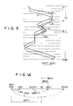
- Fig. 5 shows an example of actual recording data with respect to paper 30.
- broken line K represents a recording waveform corresponding to input signal aA represented by a solid line.
- Z represents erroneous recording data when a relative position of pen 4A with respect to paper 30 is erroneously deviated due to external disturbance occurred at time ta. This error is removed by the correcting operation of Fig. 4 at time tb.
- the recording waveform during its correcting process is represented by solid line Z1.
- the above correcting operation can be performed in accordance with equations (8) and (9) below.
- the recording waveform during the pen position correcting process is represented by alternate long and short dashed line Z2 in Fig. 5. Note that waveform of Z2 is obtained not in interval T2 shown in Fig. 5, but during movement of the pen just after the detection of an erroneous deviation of the pen.
- actual positions of pens 4A and 4B are periodically (T2) detected while pens 4A and 4B are moved to perform the recording operation in response to analog input signals aA and aB.
- the step numbers (SN(n)) and the step rotation directions (SD(n)) of motors 5A and 5B for moving the pens are calculated to correct the pen positions, so that the positions of pens 4A and 4B are corrected, as needed, while adopting an open loop controlled recording system.
- the pen position can be automatically corrected to its accurate position.
- an amount of correction of the pen position is normally zero, no practical problem will occur even if the frequency of the correcting operation is not so large.
- this position correction since a plurality of pen positions can be detected at the same time using noncontactively-operated photosensors 32A and 32B, a problem of poor contact of the potentiometer is not posed, so that a small and inexpensive pen recorder can be obtained.
- period T2 for executing the interruption processing of pen position correction shown in the flow of Fig. 4 need not be constant.
- Period T2 may be arbitrarily changed as long as it is longer than period T1 of the operation shown in the flow of Fig. 2.
- T2 may be several seconds or less.
- T2 may be several minutes or more.
- period T2 may be changed in accordance with the kinds of analog input signals to be recorded.
- Fig. 6 shows another embodiment of the present invention.
- thermal head 410 and photosensor 400 for detecting a home position are provided on sensor carriage 40.
- Head 410 writes a predetermined scale, recording conditions, recording date, and the like, on paper 30, in accordance with data supplied from CPU 24 of Fig. 1, via thermal head driver 420.
- pen position detection signals e32A and e32B are output from photosensors 32A and 32B, to thereby perform the interruption processing of Fig. 4.
- head 410 in Fig. 6 can be replaced with a wire dot print head or the like.
- Fig. 7 shows still another embodiment of the present invention.
- platen 80 is made of a transparent plastic tube, and rod-like light-emitting member 70 having a width greater than the width of paper 30 is fixed within the tube.
- the longitudinal axis of member 70 is parallel to a locus of reciprocation of carriage 40.
- Photosensor 72 opposite to member 70 is mounted to carriage 40.
- An output from photosensor 72 is supplied to CPU 24 through interrupt controller 43 in Fig. 1.
- Nontransparent paper 30 is fed between member 70 and photosensor 72.
- positions of left and right edges LE and RE of paper 30 are detected in accordance with the output level change point of photosensor 72. That is, each position of paper edges LE and RE is calculated in accordance with a count content of carriage position counter 340, using reference position x0 representing a home position of carriage 40.
- FIG. 7 An operation of the embodiment shown in Fig. 7 is the same as that of the embodiment shown in Fig. 1 when the position of edge LE coincides with position x0 or a difference between these positions is a known constant value.
- Width L varies to some extent in accordance with an individual recording sheet of paper 30. Width L also slightly varies, even for the same recording sheet, depending upon an ambient humidity.
- x represents a pen position when both ⁇ 0 and ⁇ 100 are 0, and x* represents a corrected pen position when neither ⁇ 0 nor ⁇ 100 is 0. That is, when a step rotation amount and a step rotation direction of stepping motor 5A or 5B are controlled to move pen 4A or 4B to position x* which is calculated by equation (10), an accurate waveform corresponding to input aA or aB can be drawn on paper 30, even if a deviation such as ⁇ 0 or ⁇ 100 is present.
- a pen recorder which can accurately detect positions of a plurality of pens and hence can perform recording with improved accuracy, and which is not large in size and has a high reliability because no potentiometer is required.
- a means, utilizing a Hall element or an ultrasonic wave can be used as a means for detecting positions of pens 4A and 4B, instead of a photosensor.
- the detecting means may have an arrangement in which a light-emitting element is provided at the side of the pen carriage and a light-receiving element is provided at the side of the sensor carriage.
Landscapes
- Physics & Mathematics (AREA)
- General Physics & Mathematics (AREA)
- Recording Measured Values (AREA)
Claims (9)
- Stiftaufzeichnungsgerät zum Aufzeichnen von Information eines Eingangssignals (aA) auf einem Aufzeichnungspapier (30) mittels eines Schreib-Stifts (4A), umfassend:- eine Aufzeichnungsposition-Recheneinrichtung (20A, 22A, 24, 44, 45) zum Berechnen einer Aufzeichnungsposition (xp(N)) des Stifts (4A) in Abhängigkeit vom Eingangssignal (aA),- eine Stiftstellung-Detektoreinrichtung zum Detektieren oder Erfassen einer Ist-Stellung (xp(N)) des Stifts (4A) in bezug auf eine vorbestimmte Bezugsstellung (x0),- eine Steuereinheit (24) zum Steuern des Betriebs des Aufzeichnungsgeräts und zur Durchführung einer Stiftstellung-Korrekturverarbeitung zum Korrigieren einer Stellung des Stifts (4A) entsprechend der durch die Stiftstellung-Detektoreinrichtung erfaßten Ist-Stellung (xp*(N)), so daß die Ist-Stellung mit der Aufzeichnungsposition des Stifts (4A) übereinstimmt,
dadurch gekennzeichnet, daß- die Stiftstellung-Detektoreinrichtung einen Stellungssensor (32A) aufweist, der unabhängig von der Bewegung des Stifts (4A) und parallel dazu bewegbar ist und der im Betrieb ein Stellungserfassungssignal (e32A) abgibt, das die Ist-Stellung des Stifts (4A) angibt, wenn der Sensor (32A) am Stift (4A) vorbeiläuft,- Einrichtungen (34, 35, 38, 41, 42) zum Bewegen des Sensors (32A) parallel zum Stift (4A) und unabhängig von dessen Bewegung vorgesehen sind,- die Steuereinheit (24) den Normalbetrieb periodisch oder aperiodisch anzuhalten vermag, um die Erfassung der Ist-Stellung (xp*(N)) des Stifts mittels der Stiftstellung-Detektoreinrichtung und die anschließende Korrektur der Stiftstellung in Abhängigkeit vom Stellungserfassungssignal (e32A) zu gestatten. - Aufzeichnungsgerät nach Anspruch 1,
dadurch gekennzeichnet, daß
die Steuereinheit umfaßt:
eine Verarbeitungseinheit (24) zum Berechnen einer Stiftstellung-Korrekturgröße (SN*(N), SN*(n)) und einer Stiftstellung-Korrekturrichtung (SN*(N), SN*(n)) entsprechend einer Differenz zwischen Daten der Ist-Stellung (xp*(N)) des Stifts (4A) und Daten der Aufzeichnungsposition (xp(N)) des Stifts (4A), und eine Betätigungseinrichtung (25A, 5A-12A) zum Bewegen des Stifts (4A) in einer durch die Stiftstellung-Korrekturrichtung (SN*(N), SN*(n)) repräsentierten Richtung um eine Größe entsprechend der Stiftstellung-Korrekturgröße (SN*(N) oder SN*(n)),
Einrichtungen (5A-12A, 25A, 20A, 22A, 24, 44, 45) zur Durchführung einer (rückführungslosen) Steuerung für die Bewegung des Stifts (4A) in Abhängigkeit vom Eingangssignal (aA) vorgesehen sind und
Einrichtungen (5A-12A, 25A, 24, 43) zur Durchführung einer Regelung zum Korrigieren der Stellung des Stifts (4A) in Abhängigkeit von der Stiftstellung-Korrekturgröße (SN*(N), SN*(n)) und der Stiftstellung-Korrekturrichtung (SD*(N), SD*(n)) vorgesehen sind. - Aufzeichnungsgerät nach Anspruch 1 oder 2,
dadurch gekennzeichnet, daß
der Sensor (32A) einen Photosensor (32A) mit einem Strahlengang umfaßt, der Stift (4A) mit einer Einrichtung (12A) zum Unterbrechen des Strahlengangs des Photosensors (32A) versehen ist, der Photosensor (32A) ein Signal (e32A) zur Anzeige der Ist-Stellung (xp*(N)) des Stifts (4A) erzeugt, wenn der Strahlengang des Photosensors (32A) durch die Unterbrechungseinrichtung (12A) unterbrochen ist, und der Photosensor (32A) sich parallel zur Unterbrechungseinrichtung und unabhängig von deren Bewegung bewegen kann. - Aufzeichnungsgerät nach Anspruch 2,
dadurch gekennzeichnet, daß
Einrichtungen (44) vorgesehen sind zum Speichern eines Unterbrechungsverarbeitungsprogramms, nach dem die Stiftstellung-Korrekturgröße (SN*(N), SN*(n)) und die Stiftstellung-Korrekturrichtung (SD*(N), SD*(n)) berechnet werden, und
die Verarbeitungseinheit umfaßt: einen Mikrorechner (24) zum Abarbeiten eines Programms zum Betätigen der Betätigungseinrichtung (5A-12A, 25A) in der Weise, daß sich der Stift (4A) entsprechend dem Eingangssignal (aA) bewegt, und zum Ausführen oder Abarbeiten des Unterbrechungsverarbeitungsprogramms,
und eine Unterbrechungssteuereinheit (43), um den Mikrorechner (24) das Unterbrechungsverarbeitungsprogramm abarbeiten zu lassen, wenn das Stiftstellung-Erfassungssignal (e32A) erzeugt wird. - Aufzeichnungsgerät nach Anspruch 3,
dadurch gekennzeichnet, daß
der (die) Sensor(einheit) umfaßt:
einen sich mit dem Photosensor (32A) mitbewegenden Ausgangsstellungssensor (400) zum Erzeugen eines Ausgangsstellungssignals (e400), wenn sich der Ausgangsstellungssensor (400) zur vorbestimmten Bezugsstellung (x0) bewegt, und einen Stellungszähler (340) zum Ausgeben erster Zähl(stand)daten, welche die vorbestimmte Bezugsstellung (x0) repräsentieren, wenn das Ausgangsstellungssignal (e400) erzeugt wird oder ist, und zum Ausgeben zweiter, die Ist-Stellung (xp*(N)) des Stifts (4A) repräsentierender Zähldaten, wenn das Stiftstellung-Erfassungssignal (e32A) erzeugt wird oder ist, wobei die ersten und zweiten Zähldaten dem Mikrorechner (24) für Unterbrechungsverarbeitung zugespeist werden. - Aufzeichnungsgerät nach Anspruch 1, 2 oder 3,
dadurch gekennzeichnet, daß
der (die) Sensor(einheit) eine Einrichtung (410) zum Aufschreiben von Information, die von der Aufschreibinformation des Stifts (4A) Verschieden ist, auf das Aufzeichnungspapier (30) aufweist. - Aufzeichnungsgerät nach Anspruch 3,
dadurch gekennzeichnet, daß
zwei oder mehr der Stifte (4A, 4B) und der Photosensoren (32A, 32B) vorgesehen sind und die Photosensoren (32A, 32B) sich zusammen oder gemeinsam bewegen. - Aufzeichnungsgerät nach einem der Ansprüche 1 bis 7,
ferner gekennzeichnet durch
eine Aufzeichnungspapier-Randerfassungseinrichtung (70, 72) zum Erfassen eines Rands (LE) des auf eine Druckwalze (80) des Stiftaufzeichnungsgeräts aufgezogenen Aufzeichnungspapiers (30), und wobei die Steuereinheit mit der Aufzeichnungspapier-Randerfassungseinrichtung gekoppelte Einrichtungen (24, 25A, 5A-12A) zum Berechnen eines Intervalls oder Abstands (Δ0) zwischen einer zweiten vorbestimmten Bezugsstellung (REF. POS) und dem Rand (LE) des Aufzeichnungspapiers (30), zum Durchführen der Stiftstellung-Korrek turoperation entsprechend der Ist-Stellung (xp*(N)) und der Aufzeichnungsposition (xp(N)) des Stifts (4A) sowie zum Verschieben einer Stellung des Stifts (4A) um eine Größe entsprechend dem Intervall oder Abstand (Δ0) aufweist. - Aufzeichnungsgerät nach einem der Ansprüche 1 bis 7,
dadurch gekennzeichnet, daß
es ferner Aufzeichnungspapier-Randerfassungseinrichtungen (70, 72) zum Erfassen des einen Rands (LE) und des anderen Rands (RE) des auf eine Druckwalze (80) des Stiftaufzeichnungsgeräts aufgezogenen Aufzeichnungspapiers (30) aufweist und die Steuereinheit mit den Aufzeichnungspapier-Randerfassungseinrichtungen gekoppelte Einrichtungen (24, 25A, 5A-12A) zum Brechnen eines ersten Intervalls oder Abstands (Δ0) zwischen einer zweiten vorbestimmten Bezugsstellung (0% POS.) und dem Rand (LE) des Aufzeichnungspapiers (30) sowie eines zweiten Intervalls oder Abstands (Δ100) zwischen einer dritten vorbestimmten Bezugsstellung (100% POS.) und dem anderen Rand (RE) des Aufzeichnungspapiers (30), zur Durchführung der Stiftstellung-Korrekturoperation entsprechend der Ist-Stellung (xp*(N)) und der Aufzeichnungsposition (xp(N)) des Stifts (4A) und zum Verschieben einer Stellung des Stifts (4A) um eine Korrekturgröße (X*-x) entsprechend den ersten und zweiten Intervallen (Δ0, Δ100) umfaßt.
Applications Claiming Priority (2)
| Application Number | Priority Date | Filing Date | Title |
|---|---|---|---|
| JP71175/86 | 1986-03-31 | ||
| JP61071175A JPS62228907A (ja) | 1986-03-31 | 1986-03-31 | 記録計 |
Publications (3)
| Publication Number | Publication Date |
|---|---|
| EP0243679A2 EP0243679A2 (de) | 1987-11-04 |
| EP0243679A3 EP0243679A3 (en) | 1989-01-25 |
| EP0243679B1 true EP0243679B1 (de) | 1993-06-02 |
Family
ID=13453062
Family Applications (1)
| Application Number | Title | Priority Date | Filing Date |
|---|---|---|---|
| EP87104426A Expired - Lifetime EP0243679B1 (de) | 1986-03-31 | 1987-03-25 | Schreibfederregistrierapparat mit verbesserter Genauigkeit |
Country Status (4)
| Country | Link |
|---|---|
| US (1) | US4751526A (de) |
| EP (1) | EP0243679B1 (de) |
| JP (1) | JPS62228907A (de) |
| DE (1) | DE3786039T2 (de) |
Families Citing this family (3)
| Publication number | Priority date | Publication date | Assignee | Title |
|---|---|---|---|---|
| DE3836315A1 (de) * | 1988-10-25 | 1990-05-03 | Vdo Schindling | Linienschreiber |
| US4935878A (en) * | 1989-01-04 | 1990-06-19 | Calcomp Inc. | System friction compensation in vector plotters |
| US6390508B2 (en) * | 1997-12-31 | 2002-05-21 | Matthew Levine | Method of producing a customized chart |
Family Cites Families (7)
| Publication number | Priority date | Publication date | Assignee | Title |
|---|---|---|---|---|
| US3982491A (en) * | 1974-08-12 | 1976-09-28 | Union Special Corporation | Automatic sewing machine |
| GB1602180A (en) * | 1977-04-26 | 1981-11-11 | Moyroud L M | Photographic type-composition |
| JPS6055020B2 (ja) * | 1978-02-28 | 1985-12-03 | 横河電機株式会社 | 自動平衡計器 |
| JPS5543403A (en) * | 1978-09-22 | 1980-03-27 | Tokyo Shibaura Electric Co | Fuel exchanging device |
| US4444519A (en) * | 1982-03-09 | 1984-04-24 | Theodore Jay Goldlander | Printers |
| US4591871A (en) * | 1983-10-04 | 1986-05-27 | Yokogawa Hokushin Electric Corporation | Recorder with functions to correct expansion or contraction of recording paper |
| JPH0756561B2 (ja) * | 1983-12-26 | 1995-06-14 | 株式会社東芝 | 像形成装置 |
-
1986
- 1986-03-31 JP JP61071175A patent/JPS62228907A/ja not_active Expired - Lifetime
-
1987
- 1987-03-25 DE DE8787104426T patent/DE3786039T2/de not_active Expired - Lifetime
- 1987-03-25 EP EP87104426A patent/EP0243679B1/de not_active Expired - Lifetime
- 1987-03-30 US US07/031,265 patent/US4751526A/en not_active Expired - Lifetime
Also Published As
| Publication number | Publication date |
|---|---|
| DE3786039T2 (de) | 1993-09-09 |
| JPS62228907A (ja) | 1987-10-07 |
| DE3786039D1 (de) | 1993-07-08 |
| EP0243679A2 (de) | 1987-11-04 |
| US4751526A (en) | 1988-06-14 |
| EP0243679A3 (en) | 1989-01-25 |
Similar Documents
| Publication | Publication Date | Title |
|---|---|---|
| EP0650844B1 (de) | Schwingrahmendrucker und Betriebsverfahren | |
| EP0242083B1 (de) | Kompaktzeichengerät zur Erzeugung von genau gezeichneten Bildern in langgestreckter Form | |
| US5959295A (en) | Timing device and method for positioning non-linear machine parts | |
| US4114750A (en) | Printer system having local control for dynamically alterable printing | |
| AU731248B2 (en) | Friction drive apparatus for strip material | |
| US20040026474A1 (en) | Methods for calibration and automatic alignment in friction drive apparatus | |
| US4390293A (en) | Electronic typewriter | |
| EP0243679B1 (de) | Schreibfederregistrierapparat mit verbesserter Genauigkeit | |
| US7176649B2 (en) | DC motor control apparatus and recording apparatus | |
| KR100232938B1 (ko) | 카드 처리 장치 | |
| EP0533400B1 (de) | Papierbreitefeststellung in einem Drucker | |
| US4475831A (en) | Position tracking emitter for a printer with emitter pattern on lead screw | |
| JPH02159516A (ja) | 線記録器 | |
| JPS612017A (ja) | リニア位置エンコ−ダ | |
| JP2805980B2 (ja) | レコーダ | |
| EP0161223A3 (en) | Device for regulating the draught of the strip in a hot rolling mill | |
| JPH0419475Y2 (de) | ||
| JP3040446B2 (ja) | 記録装置およびその制御方法 | |
| JPH01247179A (ja) | シリアル式ドットマトリクスプリンタ | |
| JPH04363277A (ja) | シリアルプリンタ | |
| KR100262619B1 (ko) | 차량 궤적 분석장치의 센서 에러 보정방법 | |
| JPH0626892A (ja) | 記録計 | |
| JPH0663778B2 (ja) | 記録計 | |
| JPH01101413A (ja) | 記録計 | |
| JPH0212570Y2 (de) |
Legal Events
| Date | Code | Title | Description |
|---|---|---|---|
| PUAI | Public reference made under article 153(3) epc to a published international application that has entered the european phase |
Free format text: ORIGINAL CODE: 0009012 |
|
| 17P | Request for examination filed |
Effective date: 19870422 |
|
| AK | Designated contracting states |
Kind code of ref document: A2 Designated state(s): DE FR GB |
|
| PUAL | Search report despatched |
Free format text: ORIGINAL CODE: 0009013 |
|
| AK | Designated contracting states |
Kind code of ref document: A3 Designated state(s): DE FR GB |
|
| 17Q | First examination report despatched |
Effective date: 19900813 |
|
| GRAA | (expected) grant |
Free format text: ORIGINAL CODE: 0009210 |
|
| AK | Designated contracting states |
Kind code of ref document: B1 Designated state(s): DE FR GB |
|
| REF | Corresponds to: |
Ref document number: 3786039 Country of ref document: DE Date of ref document: 19930708 |
|
| ET | Fr: translation filed | ||
| PLBE | No opposition filed within time limit |
Free format text: ORIGINAL CODE: 0009261 |
|
| STAA | Information on the status of an ep patent application or granted ep patent |
Free format text: STATUS: NO OPPOSITION FILED WITHIN TIME LIMIT |
|
| 26N | No opposition filed | ||
| REG | Reference to a national code |
Ref country code: GB Ref legal event code: IF02 |
|
| PGFP | Annual fee paid to national office [announced via postgrant information from national office to epo] |
Ref country code: FR Payment date: 20060308 Year of fee payment: 20 |
|
| PGFP | Annual fee paid to national office [announced via postgrant information from national office to epo] |
Ref country code: GB Payment date: 20060322 Year of fee payment: 20 |
|
| PGFP | Annual fee paid to national office [announced via postgrant information from national office to epo] |
Ref country code: DE Payment date: 20060323 Year of fee payment: 20 |
|
| PG25 | Lapsed in a contracting state [announced via postgrant information from national office to epo] |
Ref country code: GB Free format text: LAPSE BECAUSE OF EXPIRATION OF PROTECTION Effective date: 20070324 |