EP0243597A2 - Dispositif de réglage de la courbe de régulation d'une pompe d'injection de moteur diesel d'automobile - Google Patents
Dispositif de réglage de la courbe de régulation d'une pompe d'injection de moteur diesel d'automobile Download PDFInfo
- Publication number
- EP0243597A2 EP0243597A2 EP87102434A EP87102434A EP0243597A2 EP 0243597 A2 EP0243597 A2 EP 0243597A2 EP 87102434 A EP87102434 A EP 87102434A EP 87102434 A EP87102434 A EP 87102434A EP 0243597 A2 EP0243597 A2 EP 0243597A2
- Authority
- EP
- European Patent Office
- Prior art keywords
- vehicle
- speed
- sensor
- control
- controller
- Prior art date
- Legal status (The legal status is an assumption and is not a legal conclusion. Google has not performed a legal analysis and makes no representation as to the accuracy of the status listed.)
- Granted
Links
- 230000033228 biological regulation Effects 0.000 title claims description 11
- 238000002485 combustion reaction Methods 0.000 claims abstract description 24
- 230000007704 transition Effects 0.000 claims abstract description 13
- 238000002347 injection Methods 0.000 claims abstract description 8
- 239000007924 injection Substances 0.000 claims abstract description 8
- 230000008859 change Effects 0.000 claims description 13
- 238000010586 diagram Methods 0.000 claims description 13
- 230000001133 acceleration Effects 0.000 claims description 7
- 230000001419 dependent effect Effects 0.000 claims description 7
- 238000006073 displacement reaction Methods 0.000 claims description 5
- 230000002123 temporal effect Effects 0.000 claims description 4
- 230000003111 delayed effect Effects 0.000 claims description 2
- 238000009499 grossing Methods 0.000 claims description 2
- 230000004069 differentiation Effects 0.000 claims 2
- 230000003247 decreasing effect Effects 0.000 claims 1
- 230000001105 regulatory effect Effects 0.000 abstract description 3
- 230000006870 function Effects 0.000 description 14
- 230000003213 activating effect Effects 0.000 description 4
- 230000007423 decrease Effects 0.000 description 3
- 230000001939 inductive effect Effects 0.000 description 2
- 230000004913 activation Effects 0.000 description 1
- 230000008901 benefit Effects 0.000 description 1
- 238000006243 chemical reaction Methods 0.000 description 1
- 238000001514 detection method Methods 0.000 description 1
- 230000000694 effects Effects 0.000 description 1
- 239000000446 fuel Substances 0.000 description 1
- 238000005259 measurement Methods 0.000 description 1
- 238000000034 method Methods 0.000 description 1
- 230000008569 process Effects 0.000 description 1
- 239000000779 smoke Substances 0.000 description 1
Images


Classifications
-
- F—MECHANICAL ENGINEERING; LIGHTING; HEATING; WEAPONS; BLASTING
- F02—COMBUSTION ENGINES; HOT-GAS OR COMBUSTION-PRODUCT ENGINE PLANTS
- F02D—CONTROLLING COMBUSTION ENGINES
- F02D31/00—Use of speed-sensing governors to control combustion engines, not otherwise provided for
- F02D31/001—Electric control of rotation speed
- F02D31/007—Electric control of rotation speed controlling fuel supply
- F02D31/009—Electric control of rotation speed controlling fuel supply for maximum speed control
-
- F—MECHANICAL ENGINEERING; LIGHTING; HEATING; WEAPONS; BLASTING
- F02—COMBUSTION ENGINES; HOT-GAS OR COMBUSTION-PRODUCT ENGINE PLANTS
- F02B—INTERNAL-COMBUSTION PISTON ENGINES; COMBUSTION ENGINES IN GENERAL
- F02B3/00—Engines characterised by air compression and subsequent fuel addition
- F02B3/06—Engines characterised by air compression and subsequent fuel addition with compression ignition
Definitions
- the invention relates to a device for changing the end regulation characteristic curve starting from the nominal speed according to the preamble of claim 1 and claim 10.
- the invention is therefore based on the object of providing a generic device which makes it possible for the internal combustion engine to be operated with less noise by reducing its nominal speed, without, however, reducing the user-friendliness of the vehicle by requiring an increased number of switching operations, is affected.
- An advantage of this device according to the invention is that regardless of all the forces acting on the vehicle against the driving force when the vehicle accelerates after a switching operation, the connection speed of the internal combustion engine in the next higher gear when the gear below it is turned out lies above the nominal speed in a range in which the internal combustion engine again has a relatively high output or a high torque.
- the use of an electronic control unit as a controller enables a control map with any number of final control curves to be saved, so that even with minor changes, e.g. the payload or e.g. in the case of slight gradients, it is possible to immediately adapt the final control characteristic to the new vehicle condition.
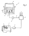
- FIG. 1 shows a diesel internal combustion engine driving a vehicle 2, on which an injection pump 3 is arranged.
- the control rod of the injection pump 3 is actuated by an actuator 4, which in turn is controlled by an electronic control unit 5.
- the control unit 5 is identical in structure and functions to the electronic diesel controller (EDR) disclosed in MTZ 44 (1983) 10 pages 378-380. The only difference is that in the control unit 5 according to the invention an additional one Operation block 14 (see FIG. 3 and FIG. 8) is provided for determining vehicle load-dependent final control characteristics, which, like the other operating parameter-dependent characteristics, are also stored in a further control characteristic in a read-only memory of control unit 5.
- the control unit 5 is also supplied via the line 6 with a signal s corresponding to the vehicle load.
- the integrating element 11 shown in broken lines is only used if the vehicle is intended for an area of application in which the vehicle load constantly changes during the journey.
- an inductive displacement sensor 9 is arranged on the rear axle 8 of the vehicle 2 and determines the distance a between the rear axle 8 and the vehicle body 10 as a measure of the loading condition of the vehicle 2.
- ⁇ R ⁇ denotes the control rod travel in the diagram and n the engine speed.
- the control rod When the vehicle is unloaded, the control rod is continuously moved into the zero delivery position according to the characteristic curve A immediately after the nominal speed n nominal has been reached. Is a certain threshold SW z of the vehicle load of z. B. If 50% of the maximum permissible payload is exceeded, the control rod is initially only minimally withdrawn in a first section I in accordance with the characteristic curve B after the nominal speed n nominal has been exceeded and only from a transition area ÜB which is approximately 25% above the nominal speed n nominal , in a second section II dropping steeply into the zero conveying position
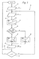
- FIG. 3 shows in the form of a flowchart the operation block 14 additionally integrated in the known electronic diesel controller for activating the final control characteristic assigned to a specific vehicle load.
- the actual payload m is determined in the operation block 17 according to a fixed characteristic 18 from the signal s. Subsequently, in the branching block 19, the query is made as to whether the payload m is too large than a predetermined threshold value SW z and at the same time the current speed n is greater than the nominal speed n nominal . If not, that is, either m is less than SW z or n is less than n nominal , the current control rod path x Rs in operation block 20 is determined in accordance with block functions 58 to 62 and 64 in FIG.
- FIG. 4 also shows a diesel engine 26 driving a vehicle with an injection pump 27, the control rod of which is actuated by an actuator 29 controlled by an electronic control unit 28.
- the control unit 28 is similar in structure and functions to the electronic diesel controller disclosed in MTZ 44 (1983) 10 on pages 378-380, but with the difference that in this control unit 28 instead of the operation block 14
- an operation block 36 (see FIG. 6 and FIG. 8) for determining a final regulation characteristic as a function of the change over time ⁇ of the engine speed is provided for the load-dependent determination of a final regulation characteristic.
- high speed n is a measure of the sum of all the forces acting on the vehicle against the driving force, such as. B. the friction force, the downhill force, etc.
- the high speed n is determined in a later place ( Figure 6), described in more detail from the engine speed n, which in addition to the other parameters 30 via the speed sensor 31 and the line 32 of the control unit 28 is supplied.
- the high-speed-dependent final control characteristics are stored in a map in the read-only memory of the control unit 28.
- Such a characteristic diagram 33 is shown in FIG. 5, in which the control rod travel x RS is in turn plotted against the engine speed n. Is the high speed of rotation h above a predetermined threshold SW A , z. B. over 250 min - '/ sec, for the determination of the current control rod path x Rs, the final control characteristic 34, which drops steeply immediately after reaching the nominal speed n nominal , should be activated.
- the current control rod travel x RS is determined from the final control characteristic curves 35, which in turn decrease only minimally in a first section I from the nominal speed n nominal and then steeply decrease in a second section II from a transition area ÜB, whereby the transition range ÜB shifts towards higher internal combustion engine speeds n as the high rotational speed h decreases, because the greater the sum of the forces acting on the vehicle against the driving force, or the smaller the high rotational speed n, the greater during a shift into the next higher gear step of the loss of speed of the vehicle (e.g. when driving uphill), or the lower the connection speed given in the next higher gear step and thus the available power to accelerate the vehicle (see also Figure 2b).
- FIG. 6 shows, in the form of a flow chart, the operation block 36 additionally integrated in the known electronic diesel controller for activating the final control characteristic assigned to a specific high speed n.
- the high speed of rotation n is determined with the aid of a timer integrated in the electronic control unit, in that the current speed of rotation n m is stored every time after a predetermined time period T m . Subsequently, the difference between the current speed n m and the speed n m - i stored after the previously expired period T m-1 is formed and related to the period T m , from which the value for the current one is derived High speed of rotation ⁇ results.
- the speed n just entered previously is first stored as n m in the operation block 41, then the current speed n m ., Stored after the previous period T m ⁇ 1 , is subtracted from this speed n m and the difference to that Time period T m related, which results in the current high speed ⁇ .
- the control then branches to point 42. If the time period T m has not yet ended (branch block 40), the control branches directly to point 42, from which the control of the individual characteristic diagrams or the individual final control characteristic curves begins. In the branching block 43, it is checked whether the current speed of rotation n is less than a predetermined threshold value SW ⁇ , which, for. B.
- the current control rod path x RS is determined in block 44 in accordance with block functions 58 to 62 and 64 in FIG. 8, otherwise x Rs is only determined as a function of the high speed of rotation ⁇ on the basis of the corresponding final control characteristic. This is done in such a way that it is determined in a first branch block 45 whether the high speed of rotation n has fallen below a first limit value GW1. If the high speed of rotation n is still above this limit value GW1, the current control rod travel x Rs is determined in block 46 according to the stored first shifted final control characteristic.
- control rod path x RS is determined according to block 48 via the end control characteristic curve that lies before that which is maximally shifted.
- the control rod path x RS results in block 49 from the latter characteristic curve when the high speed of rotation n has fallen below the i-th limit value GWi.
- the value of i can be chosen arbitrarily, depending on how exactly the final control curve is to be adapted to the high speed h.
- the current control rod path x Rs After the current control rod path x Rs has been passed on via the output block 50 to a converter in order to generate a corresponding manipulated variable signal, it is checked again in the branching block 51 whether the current speed n is above the nominal speed n nominal . If it is higher, the control branches back to point 42, because a new determination of the high speed ⁇ is only necessary when the current speed n has fallen below the nominal speed n nominal again. However, in order to be able to continue to determine the current control rod travel x RS in the area in which the current speed n is higher than the nominal speed n nominal , the current speed n must be recorded in the branch from block 51 to position 42 in a separate input block 52 will.
- the two branching blocks 43 and 51 have the effect that the high speed of rotation Camp is used as the basis for the selection of the end regulation characteristic, which is still. immediately before exceeding the nominal speed n nominal was determined and secondly that this value ⁇ is kept constant until the nominal speed is again fallen below.
- the determination of the final control characteristic curve corresponding to the respective high speed of rotation h can also be carried out with the aid of a map 54, also shown in the read-only memory of the control unit, shown in FIG. 7, which shows the relationship between the high speed of rotation ⁇ and the speed n ÜB , at which the transition range ÜB (see Figure 5) from the first to the second section of a final control characteristic.
- a map 54 also shown in the read-only memory of the control unit, shown in FIG. 7, which shows the relationship between the high speed of rotation ⁇ and the speed n ÜB , at which the transition range ÜB (see Figure 5) from the first to the second section of a final control characteristic.
- each end control characteristic can only be determined by determining its transition range ÜB or the associated speed n ÜB at a known high speed of rotation h from the stored map 54 shown in FIG. 7 be determined.
- the position of the characteristic curves in the characteristic diagram is model-dependent, with the characteristic curves 55, 56 and 57 showing
- the transition range of the most shifted final control characteristic curve is a maximum of 25% above the nominal speed n nominal .
- the end control characteristic curve can also be shifted as a function of the vehicle acceleration.
- Block 58 after checking the incoming vehicle speed v, is to be prevented by a corresponding control rod travel that a predetermined maximum speed v max can be exceeded.
- Block 59 in the event that the internal combustion engine is switched to power take-off, turns the speed n up a setpoint speed predetermined by the position ⁇ of a hand throttle control, whereby for normal driving operation in block 60 alternatively (symbolically represented by the switch 63) the speed is regulated in accordance with a conventional idle speed controller as a function of the accelerator pedal position ⁇ .
- control rod travel is to be limited such that a maximum permissible torque M perm is not exceeded, and block 62 limits the injection quantity according to a stored smoke / performance map, inter alia depending on the pressure PL and the temperature T L of a turbocharger in the combustion air of the internal combustion engine delivered charge air. From these control rod paths determined in detail, the smallest value X RS is selected in block 64.
- the additional operation block according to the invention for determining the final control characteristic curve is depicted at 14 or 36 in FIG. 8 either as a function of the signal s corresponding to the vehicle load m or as a function of the high speed h determined from the current speed n.
- the payload signal s and the speed signal n are supplied to the block 14, in the exemplary embodiment according to FIG. 4 only the speed signal n is supplied to the block 36.
- the current control rod travel x RS is predefined only by the map stored in block 66, the injection quantity in this operating state also being influenced by the internal combustion engine temperature Tg KM .
- either the control rod travel x Rs determined in block 64 or in control block 14 or 36 according to the invention is further processed. This depends on whether the payload threshold value SW z has already exceeded or exceeded. the high speed threshold SW ⁇ has already been undershot and whether or not the current speed n is above the nominal speed n nominal at the same time or not (see FIG. 3 and FIG. 6 and the associated description).
- the selection of the respective control rod travel is again represented by a symbolic switch 67 which can assume three switch positions. After a correction of the control rod path x RS by the respective fuel temperature T K in block 68, it is fed as a reference variable to a control circuit for setting and correcting the control rod to the determined position XRS '.
Landscapes
- Engineering & Computer Science (AREA)
- Chemical & Material Sciences (AREA)
- Combustion & Propulsion (AREA)
- Mechanical Engineering (AREA)
- General Engineering & Computer Science (AREA)
- Electrical Control Of Air Or Fuel Supplied To Internal-Combustion Engine (AREA)
- Control Of Vehicle Engines Or Engines For Specific Uses (AREA)
- Combined Controls Of Internal Combustion Engines (AREA)
Applications Claiming Priority (2)
| Application Number | Priority Date | Filing Date | Title |
|---|---|---|---|
| DE3613685 | 1986-04-23 | ||
| DE3613685A DE3613685C1 (de) | 1986-04-23 | 1986-04-23 | Vorrichtung zur gammanderung der Endabregelkennlinie des Reglers einer Einspritzpumpe einer ein Fahrzeug antreibenden Dieselbrennkraftmaschine |
Publications (3)
| Publication Number | Publication Date |
|---|---|
| EP0243597A2 true EP0243597A2 (fr) | 1987-11-04 |
| EP0243597A3 EP0243597A3 (en) | 1988-09-28 |
| EP0243597B1 EP0243597B1 (fr) | 1990-04-11 |
Family
ID=6299307
Family Applications (1)
| Application Number | Title | Priority Date | Filing Date |
|---|---|---|---|
| EP87102434A Expired - Lifetime EP0243597B1 (fr) | 1986-04-23 | 1987-02-20 | Dispositif de réglage de la courbe de régulation d'une pompe d'injection de moteur diesel d'automobile |
Country Status (2)
| Country | Link |
|---|---|
| EP (1) | EP0243597B1 (fr) |
| DE (2) | DE3613685C1 (fr) |
Families Citing this family (4)
| Publication number | Priority date | Publication date | Assignee | Title |
|---|---|---|---|---|
| DE3931327C1 (fr) * | 1989-09-20 | 1990-08-09 | Mercedes-Benz Aktiengesellschaft, 7000 Stuttgart, De | |
| JPH04191132A (ja) * | 1990-11-26 | 1992-07-09 | Mitsubishi Electric Corp | 車両の走行抵抗検出装置 |
| DE4138336A1 (de) * | 1991-11-21 | 1993-05-27 | Man Nutzfahrzeuge Ag | Laermarmes kraftfahrzeug, insbesondere lastkraftwagen oder omnibus |
| DE19509394C2 (de) * | 1995-03-15 | 2000-02-17 | Man Nutzfahrzeuge Ag | Regelung des Betriebsverhaltens eines Verbrennungsmotors, insbesondere Dieselmotors, eines Kraftfahrzeuges |
Family Cites Families (5)
| Publication number | Priority date | Publication date | Assignee | Title |
|---|---|---|---|---|
| US3973538A (en) * | 1973-01-06 | 1976-08-10 | C.A.V. Limited | Fuel systems for engines |
| GB1600622A (en) * | 1977-12-23 | 1981-10-21 | Lucas Industries Ltd | Fuel pumping apparatus for internal combustion engine |
| GB2069187B (en) * | 1980-02-08 | 1984-03-21 | Lucas Industries Ltd | Governor system |
| DE3101056A1 (de) * | 1981-01-15 | 1982-08-05 | Daimler-Benz Ag, 7000 Stuttgart | Verfahren und einrichtung zur ermittlung von schaltsignalen |
| DE3313632C2 (de) * | 1983-04-15 | 1986-01-30 | Daimler-Benz Ag, 7000 Stuttgart | Leerlauf-Enddrehzahlregler für Einspritzpumpen an Brennkraftmaschinen |
-
1986
- 1986-04-23 DE DE3613685A patent/DE3613685C1/de not_active Expired
-
1987
- 1987-02-20 DE DE8787102434T patent/DE3762260D1/de not_active Expired - Lifetime
- 1987-02-20 EP EP87102434A patent/EP0243597B1/fr not_active Expired - Lifetime
Also Published As
| Publication number | Publication date |
|---|---|
| DE3613685C1 (de) | 1987-03-12 |
| EP0243597A3 (en) | 1988-09-28 |
| EP0243597B1 (fr) | 1990-04-11 |
| DE3762260D1 (de) | 1990-05-17 |
Similar Documents
| Publication | Publication Date | Title |
|---|---|---|
| DE69231397T2 (de) | Vorrichtung zur drehzahlregelung bei einer fahrzeugbrennkraftmaschine | |
| DE3623676C2 (fr) | ||
| DE3728573C1 (de) | Einrichtung zum Regeln wenigstens einer das Antriebsmoment einer Brennkraftmaschine eines Kraftfahrzeuges beeinflussenden Groesse | |
| DE19953767C2 (de) | Regelsystem zum Schutz einer Brennkraftmaschine vor Überlast | |
| DE4321413C2 (de) | Verfahren und Vorrichtung zur Steuerung der Antriebsleistung eines Fahrzeugs | |
| DE19501299B4 (de) | Verfahren und Vorrichtung zur Steuerung einer Brennkraftmaschine eines Fahrzeugs | |
| EP0278232A1 (fr) | Procédé pour influencer la vitesse de déplacement d'un véhicule automobile et dispositif pour l'exécution du procédé | |
| EP0631897B1 (fr) | Procédé et dispositif pour commander une unité de propulsion d'un véhicule | |
| DE19615806B4 (de) | Verfahren und Vorrichtung zur Steuerung einer Antriebseinheit eines Fahrzeuges | |
| DE3526409C2 (fr) | ||
| EP1028242B1 (fr) | Méthode et dispositif pour réduire les vibrations du type secousses vehicule | |
| DE3933989C2 (fr) | ||
| EP0931217A1 (fr) | Procede et dispositif pour la regulation d'un moteur a combustion interne | |
| DE19611502B4 (de) | Verfahren und Vorrichtung zur Steuerung der Fahrgeschwindigkeit eines Fahrzeugs | |
| DE4417802B4 (de) | Vorrichtung zur Regelung der Motorleistung oder der Fahrgeschwindigkeit eines Fahrzeugs | |
| DE4223253C2 (de) | Steuereinrichtung für ein Fahrzeug | |
| EP0243597B1 (fr) | Dispositif de réglage de la courbe de régulation d'une pompe d'injection de moteur diesel d'automobile | |
| DE4335726B4 (de) | Verfahren und Vorrichtung zur Steuerung der Antriebsleistung eines Fahrzeugs | |
| DE69427032T2 (de) | Steuerung der kraftstoffzufuhrrate eines motors | |
| DE3919108C2 (de) | Verfahren zur Steuerung eines Betriebsparameters eines Kraftfahrzeugs bei dynamischen Betriebszuständen | |
| DE4445462A1 (de) | Verfahren und Vorrichtung zur Steuerung einer Brennkraftmaschine eines Fahrzeugs | |
| DE4426972B4 (de) | Verfahren und Vorrichtung zur Steuerung einer Brennkraftmaschine | |
| EP0250873B1 (fr) | Dispositif pour ajuster la vitesse de déplacement d'un véhicule automobile | |
| DE10039784B4 (de) | Verfahren und Vorrichtung zum Betreiben einer Brennkraftmaschine | |
| DE19806393B4 (de) | Verfahren und Vorrichtung zur Steuerung einer Antriebseinheit eines Kraftfahrzeugs |
Legal Events
| Date | Code | Title | Description |
|---|---|---|---|
| PUAI | Public reference made under article 153(3) epc to a published international application that has entered the european phase |
Free format text: ORIGINAL CODE: 0009012 |
|
| AK | Designated contracting states |
Kind code of ref document: A2 Designated state(s): DE FR GB IT NL |
|
| PUAL | Search report despatched |
Free format text: ORIGINAL CODE: 0009013 |
|
| AK | Designated contracting states |
Kind code of ref document: A3 Designated state(s): DE FR GB IT NL |
|
| 17P | Request for examination filed |
Effective date: 19881015 |
|
| 17Q | First examination report despatched |
Effective date: 19890124 |
|
| GRAA | (expected) grant |
Free format text: ORIGINAL CODE: 0009210 |
|
| AK | Designated contracting states |
Kind code of ref document: B1 Designated state(s): DE FR GB IT NL |
|
| GBT | Gb: translation of ep patent filed (gb section 77(6)(a)/1977) | ||
| ITF | It: translation for a ep patent filed | ||
| REF | Corresponds to: |
Ref document number: 3762260 Country of ref document: DE Date of ref document: 19900517 |
|
| ET | Fr: translation filed | ||
| PLBE | No opposition filed within time limit |
Free format text: ORIGINAL CODE: 0009261 |
|
| STAA | Information on the status of an ep patent application or granted ep patent |
Free format text: STATUS: NO OPPOSITION FILED WITHIN TIME LIMIT |
|
| 26N | No opposition filed | ||
| ITTA | It: last paid annual fee | ||
| PGFP | Annual fee paid to national office [announced via postgrant information from national office to epo] |
Ref country code: FR Payment date: 19921230 Year of fee payment: 7 |
|
| PGFP | Annual fee paid to national office [announced via postgrant information from national office to epo] |
Ref country code: GB Payment date: 19930119 Year of fee payment: 7 |
|
| PGFP | Annual fee paid to national office [announced via postgrant information from national office to epo] |
Ref country code: NL Payment date: 19930228 Year of fee payment: 7 |
|
| PGFP | Annual fee paid to national office [announced via postgrant information from national office to epo] |
Ref country code: DE Payment date: 19930323 Year of fee payment: 7 |
|
| PG25 | Lapsed in a contracting state [announced via postgrant information from national office to epo] |
Ref country code: GB Effective date: 19940220 |
|
| PG25 | Lapsed in a contracting state [announced via postgrant information from national office to epo] |
Ref country code: DE Effective date: 19940225 |
|
| PG25 | Lapsed in a contracting state [announced via postgrant information from national office to epo] |
Ref country code: NL Effective date: 19940901 |
|
| NLV4 | Nl: lapsed or anulled due to non-payment of the annual fee | ||
| GBPC | Gb: european patent ceased through non-payment of renewal fee |
Effective date: 19940220 |
|
| PG25 | Lapsed in a contracting state [announced via postgrant information from national office to epo] |
Ref country code: FR Effective date: 19941031 |
|
| REG | Reference to a national code |
Ref country code: FR Ref legal event code: ST |
|
| PG25 | Lapsed in a contracting state [announced via postgrant information from national office to epo] |
Ref country code: IT Free format text: LAPSE BECAUSE OF NON-PAYMENT OF DUE FEES;WARNING: LAPSES OF ITALIAN PATENTS WITH EFFECTIVE DATE BEFORE 2007 MAY HAVE OCCURRED AT ANY TIME BEFORE 2007. THE CORRECT EFFECTIVE DATE MAY BE DIFFERENT FROM THE ONE RECORDED. Effective date: 20050220 |