EP0243597A2 - Device for correcting the regulation curve of the governor of a diesel engine in a motor car - Google Patents
Device for correcting the regulation curve of the governor of a diesel engine in a motor car Download PDFInfo
- Publication number
- EP0243597A2 EP0243597A2 EP87102434A EP87102434A EP0243597A2 EP 0243597 A2 EP0243597 A2 EP 0243597A2 EP 87102434 A EP87102434 A EP 87102434A EP 87102434 A EP87102434 A EP 87102434A EP 0243597 A2 EP0243597 A2 EP 0243597A2
- Authority
- EP
- European Patent Office
- Prior art keywords
- vehicle
- speed
- sensor
- control
- controller
- Prior art date
- Legal status (The legal status is an assumption and is not a legal conclusion. Google has not performed a legal analysis and makes no representation as to the accuracy of the status listed.)
- Granted
Links
- 230000033228 biological regulation Effects 0.000 title claims description 11
- 238000002485 combustion reaction Methods 0.000 claims abstract description 24
- 230000007704 transition Effects 0.000 claims abstract description 13
- 238000002347 injection Methods 0.000 claims abstract description 8
- 239000007924 injection Substances 0.000 claims abstract description 8
- 230000008859 change Effects 0.000 claims description 13
- 238000010586 diagram Methods 0.000 claims description 13
- 230000001133 acceleration Effects 0.000 claims description 7
- 230000001419 dependent effect Effects 0.000 claims description 7
- 238000006073 displacement reaction Methods 0.000 claims description 5
- 230000002123 temporal effect Effects 0.000 claims description 4
- 230000003111 delayed effect Effects 0.000 claims description 2
- 238000009499 grossing Methods 0.000 claims description 2
- 230000004069 differentiation Effects 0.000 claims 2
- 230000003247 decreasing effect Effects 0.000 claims 1
- 230000001105 regulatory effect Effects 0.000 abstract description 3
- 230000006870 function Effects 0.000 description 14
- 230000003213 activating effect Effects 0.000 description 4
- 230000007423 decrease Effects 0.000 description 3
- 230000001939 inductive effect Effects 0.000 description 2
- 230000004913 activation Effects 0.000 description 1
- 230000008901 benefit Effects 0.000 description 1
- 238000006243 chemical reaction Methods 0.000 description 1
- 238000001514 detection method Methods 0.000 description 1
- 230000000694 effects Effects 0.000 description 1
- 239000000446 fuel Substances 0.000 description 1
- 238000005259 measurement Methods 0.000 description 1
- 238000000034 method Methods 0.000 description 1
- 230000008569 process Effects 0.000 description 1
- 239000000779 smoke Substances 0.000 description 1
Images


Classifications
-
- F—MECHANICAL ENGINEERING; LIGHTING; HEATING; WEAPONS; BLASTING
- F02—COMBUSTION ENGINES; HOT-GAS OR COMBUSTION-PRODUCT ENGINE PLANTS
- F02D—CONTROLLING COMBUSTION ENGINES
- F02D31/00—Use of speed-sensing governors to control combustion engines, not otherwise provided for
- F02D31/001—Electric control of rotation speed
- F02D31/007—Electric control of rotation speed controlling fuel supply
- F02D31/009—Electric control of rotation speed controlling fuel supply for maximum speed control
-
- F—MECHANICAL ENGINEERING; LIGHTING; HEATING; WEAPONS; BLASTING
- F02—COMBUSTION ENGINES; HOT-GAS OR COMBUSTION-PRODUCT ENGINE PLANTS
- F02B—INTERNAL-COMBUSTION PISTON ENGINES; COMBUSTION ENGINES IN GENERAL
- F02B3/00—Engines characterised by air compression and subsequent fuel addition
- F02B3/06—Engines characterised by air compression and subsequent fuel addition with compression ignition
Definitions
- the invention relates to a device for changing the end regulation characteristic curve starting from the nominal speed according to the preamble of claim 1 and claim 10.
- the invention is therefore based on the object of providing a generic device which makes it possible for the internal combustion engine to be operated with less noise by reducing its nominal speed, without, however, reducing the user-friendliness of the vehicle by requiring an increased number of switching operations, is affected.
- An advantage of this device according to the invention is that regardless of all the forces acting on the vehicle against the driving force when the vehicle accelerates after a switching operation, the connection speed of the internal combustion engine in the next higher gear when the gear below it is turned out lies above the nominal speed in a range in which the internal combustion engine again has a relatively high output or a high torque.
- the use of an electronic control unit as a controller enables a control map with any number of final control curves to be saved, so that even with minor changes, e.g. the payload or e.g. in the case of slight gradients, it is possible to immediately adapt the final control characteristic to the new vehicle condition.
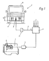
- FIG. 1 shows a diesel internal combustion engine driving a vehicle 2, on which an injection pump 3 is arranged.
- the control rod of the injection pump 3 is actuated by an actuator 4, which in turn is controlled by an electronic control unit 5.
- the control unit 5 is identical in structure and functions to the electronic diesel controller (EDR) disclosed in MTZ 44 (1983) 10 pages 378-380. The only difference is that in the control unit 5 according to the invention an additional one Operation block 14 (see FIG. 3 and FIG. 8) is provided for determining vehicle load-dependent final control characteristics, which, like the other operating parameter-dependent characteristics, are also stored in a further control characteristic in a read-only memory of control unit 5.
- the control unit 5 is also supplied via the line 6 with a signal s corresponding to the vehicle load.
- the integrating element 11 shown in broken lines is only used if the vehicle is intended for an area of application in which the vehicle load constantly changes during the journey.
- an inductive displacement sensor 9 is arranged on the rear axle 8 of the vehicle 2 and determines the distance a between the rear axle 8 and the vehicle body 10 as a measure of the loading condition of the vehicle 2.
- ⁇ R ⁇ denotes the control rod travel in the diagram and n the engine speed.
- the control rod When the vehicle is unloaded, the control rod is continuously moved into the zero delivery position according to the characteristic curve A immediately after the nominal speed n nominal has been reached. Is a certain threshold SW z of the vehicle load of z. B. If 50% of the maximum permissible payload is exceeded, the control rod is initially only minimally withdrawn in a first section I in accordance with the characteristic curve B after the nominal speed n nominal has been exceeded and only from a transition area ÜB which is approximately 25% above the nominal speed n nominal , in a second section II dropping steeply into the zero conveying position
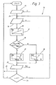
- FIG. 3 shows in the form of a flowchart the operation block 14 additionally integrated in the known electronic diesel controller for activating the final control characteristic assigned to a specific vehicle load.
- the actual payload m is determined in the operation block 17 according to a fixed characteristic 18 from the signal s. Subsequently, in the branching block 19, the query is made as to whether the payload m is too large than a predetermined threshold value SW z and at the same time the current speed n is greater than the nominal speed n nominal . If not, that is, either m is less than SW z or n is less than n nominal , the current control rod path x Rs in operation block 20 is determined in accordance with block functions 58 to 62 and 64 in FIG.
- FIG. 4 also shows a diesel engine 26 driving a vehicle with an injection pump 27, the control rod of which is actuated by an actuator 29 controlled by an electronic control unit 28.
- the control unit 28 is similar in structure and functions to the electronic diesel controller disclosed in MTZ 44 (1983) 10 on pages 378-380, but with the difference that in this control unit 28 instead of the operation block 14
- an operation block 36 (see FIG. 6 and FIG. 8) for determining a final regulation characteristic as a function of the change over time ⁇ of the engine speed is provided for the load-dependent determination of a final regulation characteristic.
- high speed n is a measure of the sum of all the forces acting on the vehicle against the driving force, such as. B. the friction force, the downhill force, etc.
- the high speed n is determined in a later place ( Figure 6), described in more detail from the engine speed n, which in addition to the other parameters 30 via the speed sensor 31 and the line 32 of the control unit 28 is supplied.
- the high-speed-dependent final control characteristics are stored in a map in the read-only memory of the control unit 28.
- Such a characteristic diagram 33 is shown in FIG. 5, in which the control rod travel x RS is in turn plotted against the engine speed n. Is the high speed of rotation h above a predetermined threshold SW A , z. B. over 250 min - '/ sec, for the determination of the current control rod path x Rs, the final control characteristic 34, which drops steeply immediately after reaching the nominal speed n nominal , should be activated.
- the current control rod travel x RS is determined from the final control characteristic curves 35, which in turn decrease only minimally in a first section I from the nominal speed n nominal and then steeply decrease in a second section II from a transition area ÜB, whereby the transition range ÜB shifts towards higher internal combustion engine speeds n as the high rotational speed h decreases, because the greater the sum of the forces acting on the vehicle against the driving force, or the smaller the high rotational speed n, the greater during a shift into the next higher gear step of the loss of speed of the vehicle (e.g. when driving uphill), or the lower the connection speed given in the next higher gear step and thus the available power to accelerate the vehicle (see also Figure 2b).
- FIG. 6 shows, in the form of a flow chart, the operation block 36 additionally integrated in the known electronic diesel controller for activating the final control characteristic assigned to a specific high speed n.
- the high speed of rotation n is determined with the aid of a timer integrated in the electronic control unit, in that the current speed of rotation n m is stored every time after a predetermined time period T m . Subsequently, the difference between the current speed n m and the speed n m - i stored after the previously expired period T m-1 is formed and related to the period T m , from which the value for the current one is derived High speed of rotation ⁇ results.
- the speed n just entered previously is first stored as n m in the operation block 41, then the current speed n m ., Stored after the previous period T m ⁇ 1 , is subtracted from this speed n m and the difference to that Time period T m related, which results in the current high speed ⁇ .
- the control then branches to point 42. If the time period T m has not yet ended (branch block 40), the control branches directly to point 42, from which the control of the individual characteristic diagrams or the individual final control characteristic curves begins. In the branching block 43, it is checked whether the current speed of rotation n is less than a predetermined threshold value SW ⁇ , which, for. B.
- the current control rod path x RS is determined in block 44 in accordance with block functions 58 to 62 and 64 in FIG. 8, otherwise x Rs is only determined as a function of the high speed of rotation ⁇ on the basis of the corresponding final control characteristic. This is done in such a way that it is determined in a first branch block 45 whether the high speed of rotation n has fallen below a first limit value GW1. If the high speed of rotation n is still above this limit value GW1, the current control rod travel x Rs is determined in block 46 according to the stored first shifted final control characteristic.
- control rod path x RS is determined according to block 48 via the end control characteristic curve that lies before that which is maximally shifted.
- the control rod path x RS results in block 49 from the latter characteristic curve when the high speed of rotation n has fallen below the i-th limit value GWi.
- the value of i can be chosen arbitrarily, depending on how exactly the final control curve is to be adapted to the high speed h.
- the current control rod path x Rs After the current control rod path x Rs has been passed on via the output block 50 to a converter in order to generate a corresponding manipulated variable signal, it is checked again in the branching block 51 whether the current speed n is above the nominal speed n nominal . If it is higher, the control branches back to point 42, because a new determination of the high speed ⁇ is only necessary when the current speed n has fallen below the nominal speed n nominal again. However, in order to be able to continue to determine the current control rod travel x RS in the area in which the current speed n is higher than the nominal speed n nominal , the current speed n must be recorded in the branch from block 51 to position 42 in a separate input block 52 will.
- the two branching blocks 43 and 51 have the effect that the high speed of rotation Camp is used as the basis for the selection of the end regulation characteristic, which is still. immediately before exceeding the nominal speed n nominal was determined and secondly that this value ⁇ is kept constant until the nominal speed is again fallen below.
- the determination of the final control characteristic curve corresponding to the respective high speed of rotation h can also be carried out with the aid of a map 54, also shown in the read-only memory of the control unit, shown in FIG. 7, which shows the relationship between the high speed of rotation ⁇ and the speed n ÜB , at which the transition range ÜB (see Figure 5) from the first to the second section of a final control characteristic.
- a map 54 also shown in the read-only memory of the control unit, shown in FIG. 7, which shows the relationship between the high speed of rotation ⁇ and the speed n ÜB , at which the transition range ÜB (see Figure 5) from the first to the second section of a final control characteristic.
- each end control characteristic can only be determined by determining its transition range ÜB or the associated speed n ÜB at a known high speed of rotation h from the stored map 54 shown in FIG. 7 be determined.
- the position of the characteristic curves in the characteristic diagram is model-dependent, with the characteristic curves 55, 56 and 57 showing
- the transition range of the most shifted final control characteristic curve is a maximum of 25% above the nominal speed n nominal .
- the end control characteristic curve can also be shifted as a function of the vehicle acceleration.
- Block 58 after checking the incoming vehicle speed v, is to be prevented by a corresponding control rod travel that a predetermined maximum speed v max can be exceeded.
- Block 59 in the event that the internal combustion engine is switched to power take-off, turns the speed n up a setpoint speed predetermined by the position ⁇ of a hand throttle control, whereby for normal driving operation in block 60 alternatively (symbolically represented by the switch 63) the speed is regulated in accordance with a conventional idle speed controller as a function of the accelerator pedal position ⁇ .
- control rod travel is to be limited such that a maximum permissible torque M perm is not exceeded, and block 62 limits the injection quantity according to a stored smoke / performance map, inter alia depending on the pressure PL and the temperature T L of a turbocharger in the combustion air of the internal combustion engine delivered charge air. From these control rod paths determined in detail, the smallest value X RS is selected in block 64.
- the additional operation block according to the invention for determining the final control characteristic curve is depicted at 14 or 36 in FIG. 8 either as a function of the signal s corresponding to the vehicle load m or as a function of the high speed h determined from the current speed n.
- the payload signal s and the speed signal n are supplied to the block 14, in the exemplary embodiment according to FIG. 4 only the speed signal n is supplied to the block 36.
- the current control rod travel x RS is predefined only by the map stored in block 66, the injection quantity in this operating state also being influenced by the internal combustion engine temperature Tg KM .
- either the control rod travel x Rs determined in block 64 or in control block 14 or 36 according to the invention is further processed. This depends on whether the payload threshold value SW z has already exceeded or exceeded. the high speed threshold SW ⁇ has already been undershot and whether or not the current speed n is above the nominal speed n nominal at the same time or not (see FIG. 3 and FIG. 6 and the associated description).
- the selection of the respective control rod travel is again represented by a symbolic switch 67 which can assume three switch positions. After a correction of the control rod path x RS by the respective fuel temperature T K in block 68, it is fed as a reference variable to a control circuit for setting and correcting the control rod to the determined position XRS '.
Landscapes
- Engineering & Computer Science (AREA)
- Chemical & Material Sciences (AREA)
- Combustion & Propulsion (AREA)
- Mechanical Engineering (AREA)
- General Engineering & Computer Science (AREA)
- Electrical Control Of Air Or Fuel Supplied To Internal-Combustion Engine (AREA)
- Control Of Vehicle Engines Or Engines For Specific Uses (AREA)
- Combined Controls Of Internal Combustion Engines (AREA)
Abstract
Description
Die Erfindung betrifft eine Vorrichtung zur Änderung der ab Nenndrehzahl beginnenden Endabregelkennlinie gemäß Oberbegriff des Anspruches 1 und des Anspruches 10.The invention relates to a device for changing the end regulation characteristic curve starting from the nominal speed according to the preamble of
Aus der DE-OS 33 13 632 ist es bekannt, durch bedarfweises Variieren der Vorspannung der Hauptregelfeder eines mechanischen Reglers durch einen über ein 3/2-Wegeventil angesteuerten Stellkolben die Endabregelkennlinie des Reglers in Abhängigkeit von z.B. der Fahrzeuggeschwindigkeit oder der Getriebeabstufung zu verändern.From DE-OS 33 13 632 it is known, by varying the pretension of the main control spring of a mechanical controller, if necessary, by means of an actuating piston controlled by a 3/2-way valve, the end limiting characteristic of the controller depending on e.g. to change the vehicle speed or the gear ratio.
Ferner geht aus dem Artikel "Elektronische Diesel-Regelung EDR für Nutzfahrzeugmotoren" in der MTZ 44 (1983) 10 S. 378 - 380 ein elektronischer Regler für eine Dieselbrennkraftmaschine hervor, mittels dem durch eine entsprechende Programmierung die Brennkraftmaschinencharakteristik bzw. die Fahrcharakteristik eines durch die Brennkraftmaschine angetriebenen Fahrzeuges beeinflußt werden kann.Furthermore, the article "Electronic Diesel Regulation EDR for Commercial Vehicle Engines" in MTZ 44 (1983) 10 p. 378-380 shows an electronic controller for a diesel internal combustion engine, by means of which the internal combustion engine characteristics or the driving characteristics of one by the Internal combustion engine driven vehicle can be influenced.
Wie jedoch eine Vorrichtung ausgestaltet sein muß, die die Endabregelkennlinie eines Reglers derart ändert, daß einerseits die Brennkraftmaschine zur Reduzierung der Geräuschemission mit einer niederen Nenndrehzahl betrieben werden kann, jedoch andererseits, um nach einem Schaltvorgang nach wie vor ausreichend hohe Anschlußdrehzahlen zu haben, eine engere Getriebeabstufung dennoch nicht erforderlich ist, darüber ist in den beiden Druckschriften nichts ausgesagt.How should a device be designed, however, that changes the end control characteristic of a controller in such a way that the internal combustion engine can be operated at a low nominal speed to reduce noise emissions, but on the other hand, in order to have sufficiently high connection speeds after a switching operation, a narrower one Gear gradation is not required, nothing is said about that in the two publications.
Der Erfindung liegt daher die Aufgabe zugrunde, eine gattungsgemäße Vorrichtung zu - schaffen, die es ermöglicht, daß die Brennkraftmaschine durch eine Reduzierung ihrer Nenndrehzahl geräuschärmer betrieben werden kann, ohne daß jedoch die Benutzerfreundlichkeit des Fahrzeuges dadurch, daß eine erhöhte Anzahl an Schaltvorgängen erforderlich ist, beeinträchtigt wird.The invention is therefore based on the object of providing a generic device which makes it possible for the internal combustion engine to be operated with less noise by reducing its nominal speed, without, however, reducing the user-friendliness of the vehicle by requiring an increased number of switching operations, is affected.
Die Aufgabe wird erfindungsgemäß durch die Merkmale des kennzeichnenden Teiles der Patentansprüche 1 oder 10 gelöst.The object is achieved by the features of the characterizing part of
Ein Vorteil dieser erfindungsgemäßen Vorrichtung besteht darin, daß unabhängig von sämtlichen auf das Fahrzeug entgegen der Antriebskraft wirkenden Kräften bei der Beschleunigung des Fahrzeuges nach einem Schaltvorgang die Anschlußdrehzahl der Brennkraftmaschine im nächsthöheren Gang bei Ausdrehen des darunterliegenden Ganges über Nenndrehzahl in einem Bereich liegt, in welchem seitens der Brennkraftmaschine schon wieder eine relativ hohe Leistung bzw. ein hohes Drehmoment zur Verfügung steht. Dabei ermöglicht es die Verwendung einer elektronischen Steuereinheit als Regler, daß ein Regelkennfeld mit beliebig vielen Endabregelkennlinien abgespeichert werden kann, wodurch schon bei geringen Änderungen z.B. der Zuladung oder z.B. bei geringfügigen Steigungen eine sofortige Anpassung der Endabregelkennlinie an den neuen Fahrzeugzustand möglich ist.An advantage of this device according to the invention is that regardless of all the forces acting on the vehicle against the driving force when the vehicle accelerates after a switching operation, the connection speed of the internal combustion engine in the next higher gear when the gear below it is turned out lies above the nominal speed in a range in which the internal combustion engine again has a relatively high output or a high torque. The use of an electronic control unit as a controller enables a control map with any number of final control curves to be saved, so that even with minor changes, e.g. the payload or e.g. in the case of slight gradients, it is possible to immediately adapt the final control characteristic to the new vehicle condition.
Weitere vorteilhafte Ausgestaltungen der Erfindung sind den Unteransprüchen 2 bis 9 und 11 bis 15 zu entnehmen.Further advantageous refinements of the invention can be found in subclaims 2 to 9 and 11 to 15.
In der Zeichnung zeigt:
Figur 1 ein Ausführungsbeispiel einer erfindungsgemäßen Vorrichtung zur zuladungsabhängigen Änderung der Endabregelkennlinie in einer Prinzipdarstellung,- Figur 2a in einem Diagramm xRS = f(n) den Einfluß einer bestimmten Fahrzeugzuladung auf den Endabregelverlauf,
- Figur 2b in einem Diagramm N = F(n) den Einfluß der Verschiebung der Endabregelkennlinien auf die jeweiligen Anschlußdrehzahlen,
Figur 3 in einem Flußdiagramm den Operationsblock zur Aktivierung der einer bestimmten Fahrzeugzuladung zugeordneten Endabregelkennlinie,Figur 4 ein Ausführungsbeispiel einer erfindungsgemäßen Vorrichtung zur Änderung der Endabregelkennlinie in Abhängigkeit von der zeitlichen Änderung der Brennkraftmaschinendrehzahl in einer Prinzipdarstellung,Figur 5 in einem Diagramm xRS = f(n) den Einfluß der zeitlichen Änderung der Brennkraftmaschinendrehzahl auf den Endabregelverlauf,- Figur 6 in einem Flußdiagramm, den Operationsblock zur Aktivierung der einer bestimmten zeitlichen Änderung der Brennkraftmaschinendrehzahl zugeordneten Endabregelkennlinie,
- Figur 7 in einem Diagramm n üB = f(n) den Einfluß der zeitlichen Änderung der Brennkraftmaschinendrehzahl auf die Verschiebung der Endabregelkennlinie und
- Figur 8 die Blockfunktionen der elektronischen Steuereinheit in einem Blockschaltbild.
- FIG. 1 shows an exemplary embodiment of a device according to the invention for changing the end-regulating characteristic depending on the load, in a basic illustration,
- FIG. 2a shows in a diagram x RS = f (n) the influence of a specific vehicle load on the course of the final control,
- FIG. 2b shows in a diagram N = F (n) the influence of the shift in the end regulation characteristics on the respective connection speeds,
- FIG. 3 is a flowchart of the operation block for activating the final control characteristic assigned to a specific vehicle load,
- FIG. 4 shows an exemplary embodiment of a device according to the invention for changing the final control characteristic as a function of the change in the engine speed over time in a basic illustration,
- FIG. 5 shows in a diagram x RS = f (n) the influence of the change in the engine speed over time on the end control curve,
- FIG. 6 shows in a flowchart the operation block for activating the final control characteristic associated with a specific change in the engine speed over time.
- FIG. 7 shows in a diagram n ü B = f (n) the influence of the temporal change in the engine speed on the shift in the final control characteristic and
- Figure 8 shows the block functions of the electronic control unit in a block diagram.
In Figur 1 zeigt 1 eine ein Fahrzeug 2 antreibende Dieselbrennkraftmaschine, an der eine Einspritzpumpe 3 angeordnet ist. Die Regelstange der Einspritzpumpe 3 wird über einen Stellantrieb 4 betätigt, der wiederum durch eine elektronische Steuereinheit 5 angesteuert wird. Die Steuereinheit 5 gleicht in ihrem Aufbau und in ihren Funktionen dem in der MTZ 44 (1983) 10 Seiten 378 - 380 offenbarten elektronischen Dieselregler (EDR). Ein Unterschied besteht nur darin, daß in der erfindungsgemäßen Steuereinheit 5 zusätzlich noch ein Operationsblock 14 (siehe Figur 3 und Figur 8) zur Ermittlung von fahrzeugzuladungsabhängigen Endabregelkennlinien vorgesehen ist, die ebenfalls wie die übrigen betriebsparameterabhängigen Kennfelder in einem weiteren Regelkennfeld in einem Festwertspeicher der Steuereinheit 5 abgelegt sind. Der erfindungsgemäßen Steuereinheit 5 wird, neben den Meßwerten 7, die auch dem bekannten elektronischen Dieselregler EDR zugeführt werden, über die Leitung 6 noch ein der Fahrzeugzuladung entsprechendes Signal s zugeführt. Das gestrichelt dargestellte Integrierglied 11 wird nur dann eingesetzt, wenn das Fahrzeug für einen Einsatzbereich vorgesehen ist, in dem sich die Fahrzeugzuladung während der Fahrt ständig ändert. Zur Erstellung des Signals s ist auf der Hinterachse 8 des Fahrzeuges 2 ein induktiver Weggeber 9 angeordnet, der den Abstand a zwischen der Hinterachse 8 und dem Fahrzeugaufbau 10 als Maß für den Beladungszustand des Fahrzeuges 2 ermittelt.In FIG. 1, 1 shows a diesel internal combustion engine driving a vehicle 2, on which an
Figur 2a zeigt in einem Diagramm xRS = f(n) den qualitativen Verlauf eines im Festwertspeicher der Steuereinheit 5 abgelegten Regelkennfeldes 12 mit einer Endabregelkennlinie A für ein unbeladendes und einer Endabregelkennlinie B für ein beladendes Fahrzeug. ×Rε bezeichnet in dem Diagramm den Regelstangenweg und n die Brennkraftmaschinendrehzahl.FIG. 2a shows in a diagram x RS = f (n) the qualitative course of a
Bei unbeladenem Fahrzeug wird die Regelstange gemäß dem Kennlinienverlauf A unmittelbar nach Erreichen der Nenndrehzahl nNenn kontinuierlich in die Nullförderlage geführt. Ist ein bestimmter Schwellwert SWz der Fahrzeugzuladung von z. B. 50 % der maximal zulässigen Zuladung überschritten, so wird die Regelstange gemäß des Kennlinienverlaufes B nach Überschreiten der Nenndrehzahl nNenn in einem ersten Abschnitt I zunächst nur minimal zurückgenommen und erst ab einem Übergangsbereich ÜB, der ungefähr 25 % über der Nenndrehzahl nNenn liegt, in einem zweiten Abschnitt II steil abfallend in die Nullförderlage geführtWhen the vehicle is unloaded, the control rod is continuously moved into the zero delivery position according to the characteristic curve A immediately after the nominal speed n nominal has been reached. Is a certain threshold SW z of the vehicle load of z. B. If 50% of the maximum permissible payload is exceeded, the control rod is initially only minimally withdrawn in a first section I in accordance with the characteristic curve B after the nominal speed n nominal has been exceeded and only from a transition area ÜB which is approximately 25% above the nominal speed n nominal , in a second section II dropping steeply into the zero conveying position
Anhand des in Figur 2b dargestellten Diagrammes N = f(n), welches qualitativ die Abhängigkeit der Brennkraftmaschinenleistung N von der Brennkraftmaschinendrehzahl n aufzeigt, ist zu erkennen, daß eine derartige Ansteuerung der Regelstange dazu führt, daß oberhalb der Nenndrehzahl nNenn bzgl. eines konstanten Leistungsangebotes NK der Brennkraftmaschine deren Drehzahl n B bei beladenem Fahrzeug immer höher liegt als die Drehzahl n A bei unbeladenem Fahrzeug. Demzufolge liegt auch nach einem Schaltvorgang in die nächsthöhere Gangstufe die Anschlußdrehzahl nB ' bei beladenem Fahrzeug höher als die Anschlußdrehzahl nA ' bei unbeladenem Fahrzeug, wodurch dem beladenen Fahrzeug unmittelbar nach dem Schaltvorgang für die weitere Beschleunigung gemäß der Leistungskennlinie 13 eine um AN höhere Leistung als dem unbeladenen Fahrzeug zur Verfügung steht. Für ein beladenes Fahrzeug muß nach dem Schaltvorgang deshalb eine relativ hohe Anschlußdrehzahl gegeben sein, da ansonsten die erforderliche Leistung, um das beladene Fahrzeug noch zu beschleunigen nicht verfügbar ist, was ein Drehzahlabfall zur Folge hat, wodurch ein Rückschalten in die nächstniedere Gangstufe unumgänglich wird. Um den Endabregelverlauf an die Zuladung noch besser anzupassen, können auch noch weitere Endabregelkennlinien, die zwischen der Standardkennlinie A und der maximal verschobenen Kennlinie B liegen, abgespeichert werden. So ist es z. B. denkbar, daß für die Regelstangensteuerung je 10 % Zuladungserhöhung eine um ca. 2,5 % der Nenndrehzahl nNenn verschobene Endabregelkennlinie zugrundegelegt wird.On the basis of the diagram N = f (n) shown in FIG. 2b, which qualitatively shows the dependency of the engine power N on the engine speed n, it can be seen that such control of the control rod leads to the fact that above the nominal speed n nominal with respect to a constant Performance range N K of the internal combustion engine whose speed n B when the vehicle is loaded is always higher than the speed n A when the vehicle is not loaded. Accordingly, even after a shift in the next higher gear stage, the connection speed n B 'when the vehicle is loaded is higher than the connection speed n A ' when the vehicle is unloaded, so that the loaded vehicle immediately after the shift for further acceleration according to the
Figur 3 zeigt in Form eines Flußdiagrammes den in den bekannten elektronischen Dieselregler zusätzlich integrierten Operationsblock 14 zur Aktivierung der einer bestimmten Fahrzeugzuladung zugeordneten Endabregelkennlinie.FIG. 3 shows in the form of a flowchart the
Nach Erfassung des der Zuladung entsprechenden Signal s und der aktuellen Brennkraftmaschinendrehzahl n, in den Eingabeblöcken 15 und 16 wird in dem Operationsblock 17 nach einer fest vorgegebenen Kennlinie 18 aus dem Signal s die tatsächliche Zuladung mzu ermittelt. Anschließend erfolgt in dem Verzweigungsblock 19 die Abfrage, ob die Zuladung mzugrößer als ein vorgegebener Schwellwert SWz und gleichzeitig die aktuelle Drehzahl n größer als die Nenndrehzahl nNenn ist. Wenn nicht, d. h. ist entweder mzu kleiner als SWz oder n kleiner als nNenn wird der aktuelle Regelstangenweg x Rs in dem Operationsblock 20 gemäß den Blockfunktionen 58 bis 62 und 64 in Figur 8 bestimmt, andernfalls wird der aktuelle Regelstangenweg x Rs in dem Operationsblock 21 nur noch in Abhängigkeit der Zuladung, d. h. aus dem im Festwertspeicher abgelegten Kennfeld, welches die Endabregelkennlinie B enthält, ermittelt. In diesem Drehzahlbereich bleiben bei der Bestimmung des Regelstangenweges xRsdie übrigen Parameter, wie z. B. Ladedruck PL, Ladelufttemperatur TLusw. (siehe Figur 8), unberücksichtigt.After detection of the signal s corresponding to the payload and the current internal combustion engine speed n, in the
Nach der Ermittlung des aktuellen Regelstangenweges xRS nach einem der Blöcke 20 oder 21 wird diese Größe xRS über den Ausgabeblock 22 an einen geeigneten Umformer zur Wandlung in ein Stellwertsignal für den Stellantrieb 4 (siehe Figur 1) übergeben. Anschließend findet in dem Verzweigungsblock 23 noch die Überprüfung statt, ob die aktuelle Fahrzeuggeschwindigkeit v gleich 0 ist. Wenn ja, verzweigt die Steuerung zu ihrem Startpunkt, andernfalls an die Stelle 24, nach der im Block 16 die aktuelle Drehzahl n eingegeben wird. Die Eingabe der Zuladung über das Signal s erfolgt in diesem Fall nämlich nur bei stehendem Fahr zeug, da ein solches normalerweise nur im Stillstand be-und entladen wird. Solange also die Fahrzeuggeschwindigkeit v ungleich 0 ist, liegt für die Aktivierung einer Endabregelkennlinie der Zuladungswert mzu zugrunde, der beim letzten Stillstand des Fahrzeuges erfaßt worden ist. Sollte ein Einsatzbereich vorgesehen sein, bei dem sich die Zuladung während der Fahrt verändert, kann das Signal s auch permanent eingegeben werden, wobei dann der Geschwindigkeitsabfrageblock 23 entfällt und die Steuerung nach der Ausgabe von xRs im Block 22 wieder direkt zu ihrem Startpunkt zurückkehrt (siehe gestrichelte Linie 25). Für diesen Fall ist es zweckmäßig in der Leitung 6 ein das Signal s glättendes Integrierglied 11 (siehe Figur 1 gestrichelte Darstellung) vorzusehen, um zu verhindem, daß das der Steuereinheit 5 zuzuführende Meßsignal aufgrund der sich während der Fahrt ständig ändernden dynamischen Achslasten zeitweise zu stark verfälscht ist.
- Anstelle eines induktiven Weggebers kann auch ein auf der Unterseite des Fahrzeugaufbaus angeordnetes Schaltglied mit verzögerter Kontaktgabe, das von der Fahrzeugachse aus je nach Einfederung betätigt wird, verwendet werden. Ist eine bestimmte Zuladung mzu erreicht, gibt das Schaltglied, jedoch erst dann, wenn es länger als eine vorgegebene Zeitdauer ununterbrochen betätigt worden ist, ein Signal zum Aufruf der Endabregelkennlinie B (siehe Figur 2a) an die Steuereinheit weiter. Mit diesem Schaltglied wird für den Fall einer sich während der Fahrt ändernder Beladung ebenfalls berücksichtigt, daß das den Abstand a zwischen der Fahrzeugachse und dem Fahrzeugaufbau erfassende Schaltglied infolge variierender dynamischer Achslasten kurzfristig einen höheren Beladungszustand als tatsächlich vorhanden signalisieren kann.
- Instead of an inductive displacement sensor, a switching element with delayed contact, which is arranged on the underside of the vehicle body and which is actuated from the vehicle axle depending on the deflection, can also be used. If a specific payload m is reached, the switching element, but only when it has been operated continuously for longer than a predetermined period of time, forwards a signal for calling up the end regulation characteristic curve B (see FIG. 2a) to the control unit. With this switching element, in the case of a load that changes during the journey, it is also taken into account that the switching element, which detects the distance a between the vehicle axle and the vehicle body, can briefly signal a higher loading state than actually present due to varying dynamic axle loads.
Figur 4 zeigt ebenfalls eine ein Fahrzeug antreibende Dieselbrennkraftmaschine 26 mit einer Einspritzpumpe 27, deren Regelstange von einem über eine elektronische Steuereinheit 28 angesteuerten Stellantrieb 29 betätigt wird. Auch in diesem Ausführungsbeispiel gleicht die Steuer einheit 28 in ihrem Aufbau und in ihren Funktionen dem in der MTZ 44 (1983) 10 auf den Seiten 378 - 380 offenbarten elektronischen Dieselregler, allerdings mit dem Unterschied, daß in dieser Steuereinheit 28 anstelle des Operationsblockes 14 zur zuladungsabhängigen Ermittlung einer Endabregelkennlinie zusätzlich ein Operationsblock 36 (siehe Figur 6 und Figur 8) zur Ermittlung einer Endabregelkennlinie in Abhängigkeit der zeitlichen Änderung ṅ der Brennkraftmaschinendrehzahl vorgesehen ist. Diese zeitliche Änderung ṅ in der Brennkraftmaschinendrehzahi, im weiteren Verlauf "Hochdrehgeschwindigkeit n " genannt, ist ein Maß für die Summe sämtlicher auf das Fahrzeug entgegen der Antriebskraft wirkenden Kräfte, wie z. B. der Reibkraft, der Hangabtriebskraft usw.. Die Hochdrehgeschwindigkeit n wird dabei in einer an späterer Stelle (Figur 6), noch näher beschriebenen Art und Weise aus der Brennkraftmaschinendrehzahl n ermittelt, die neben den übrigen Parametern 30 über den Drehzahlsensor 31 und die Leitung 32 der Steuereinheit 28 zugeführt wird. Auch in dieser Steuereinheit sind die hochdrehgeschwindigkeitsabhängigen Endabregelkennlinien in einem Kennfeld'im Festwertspeicher der Steuereinheit 28 abgelegt.FIG. 4 also shows a
Ein solches Kennfeld 33 zeigt die Figur 5, in der wiederum der Regelstangenweg xRS über der Brennkraftmaschinendrehzahl n aufgetragen ist. Liegt die Hochdrehgeschwindigkeit h über einem vorgegebenen Schwellwert SWA , z. B. über 250 min-'/sec, soll für die Ermittlung des aktuellen Regelstangenweges x Rs die Endabregelkennlinie 34 die unmittelbar nach Erreichen der Nenndrehzahl nNenn steil abfällt, aktiviert werden. Nach Unterschreiten dieses Schwellwertes SW6 wird der aktuelle Regelstangenweg x RS aus den Endabregelkennlinien 35 ermittelt, die wiederum ab der Nenndrehzahl nNenn in je einem ersten Abschnitt I zunächst nur minimal und ab je einem Übergangsbereich ÜB schließlich in je einem zweiten Abschnitt II steil abfallen, wobei sich der Übergangsbereich ÜB mit sinkender Hochdrehgeschwindigkeit h in Richtung höherer Brenn kraftmaschinendrehzahlen n verschiebt, denn je größer die Summe der auf das Fahrzeug entgegen der Antriebskraft wirkenden Kräfte ist, bzw. je kleiner die Hochdrehgeschwindigkeit n ist, desto größer ist während eines Schaltvorganges in die nächsthöhere Gangstufe der Geschwindigkeits verlust des Fahrzeuges (z. B. bei Bergfahrt), bzw. desto geringer ist die in der nächsthöheren Gangstufe gegebene Anschlußdrehzahl und somit auch die verfügbare Leistung um das Fahrzeug noch zu beschleunigen (siehe auch Figur 2b).Such a characteristic diagram 33 is shown in FIG. 5, in which the control rod travel x RS is in turn plotted against the engine speed n. Is the high speed of rotation h above a predetermined threshold SW A , z. B. over 250 min - '/ sec, for the determination of the current control rod path x Rs, the final control characteristic 34, which drops steeply immediately after reaching the nominal speed n nominal , should be activated. After falling below this threshold value SW 6 , the current control rod travel x RS is determined from the final control
Figur 6 zeigt in Form eines Flußdiagrammes den in den bekannten elektronischen Dieselregler zusätzlich integrierten Operationsblock 36 zur Aktivierung der einer bestimmten Hochdrehgeschwindigkeit n zugeordneten Endabregelkennlinie. Die Hochdrehgeschwindigkeit n wird dabei mit Hilfe eines in der elektronischen Steuereinheit integrierten Zeitgebers ermittelt, indem immer nach Ablauf einer fest vorgegebenen Zeit spanne Tm die gerade aktuelle Drehzahl n m abgespeichert wird. Daran anschließend wird die Differenz aus der gerade aktuellen Drehzahl nmund der nach der zuvor abgelaufenen Zeitspanne Tm-1 abgespeicherten Drehzahl nm-i gebildet und auf die Zeitspanne Tm bezogen, woraus sich der Wert für die aktuelle Hochdrehgeschwindigkeit ṅ ergibt. Dabei ist das Ende einer Zeitspanne Tm.i gleichzeitig immer der Beginn der nächsten Zeitspanne Tm, wobei die einzelnen Zeitspannen alle gleich sind (Tm. 1 = Tm = T).FIG. 6 shows, in the form of a flow chart, the
Der Ablauf im einzelnen sieht wie folgt aus: Nach Festlegen einer Ausgangshochdrehgeschwindigkeit ṅ o, die als Startwert beliebig sein kann, und der konstanten Zeitspanne T=Tm. 1=Tmzwischen zwei Drehzahlabspeicherungen im Block 37 erfolgt im Eingabeblock 38 die Übernahme der aktuellen Drehzahl n. Im Operationsblock 39 wird dann die jeweils aktuelle Hochdrehgeschwindigkeit ṅ ermittelt und zwar erfolgt in dem Verzweigungsblock 40 zunächst die Überprüfung, ob die vorgegebene Zeitspanne T m zur Speicherung der nächsten aktuellen Drehzahl nm schon abgelaufen ist. Ist dies der Fall, wird im Operationsblock 41 zuerst die gerade zuvor eingegebene Drehzahl n als nm abgespeichert, anschließend von dieser Drehzahl nm die nach Ablauf der vorangegangenen Zeitspanne Tm-1 abgespeicherte aktuelle Drehzahl nm., subtrahiert und die Differenz auf die Zeitspanne Tm bezogen, woraus sich die aktuelle Hochdrehgeschwindigkeit ṅ ergibt. Anschließend verzweigt die Steuerung zur Stelle 42. ist die Zeitspanne Tm noch nicht vorüber (Verzweigungsblock 40), verzweigt die Steuerung direkt zur Stelle 42, von der aus die Ansteuerung der einzelnen Kennfelder bzw. der einzelnen Endabregelkennlinien beginnt. Im Verzweigungsblock 43 wird überprüft, ob die aktuelle Hochdrehgeschwindigkeit n kleiner ist als ein vorgegebener Schwellwert SWṅ , der z. B. zwischen 200 und 300 min-'/sec liegt und ob gleichzeitig die aktuelle Drehzahl n die Nenndrehzahl nNenn schon überschritten hat. Falls nein, wird der aktuelle Regelstangenweg xRS in dem Block 44 gemäß den Blockfunktionen 58 bis 62 und 64 in Figur 8 bestimmt, andernfalls erfolgt die Ermittlung von xRs nur noch in Abhängigkeit der Hochdrehgeschwindigkeit ṅ unter Zugrundelegung der entsprechenden Endabregelkennlinie. Dies geschieht derart, daß in einem ersten Verzweigungsblock 45 festgestellt wird, ob die Hochdrehgeschwindigkeit n einen ersten Grenzwert GW1 unterschritten hat. Liegt die Hochdrehgeschwindigkeit n noch über diesem Grenzwert GW1, erfolgt in Block 46 die Ermittlung des aktuellen Regelstangenweges xRs nach der abgespeicherten ersten verschobenen Endabregelkennlinie. Hat die Hochdrehgeschwindigkeit ṅ den Grenzwert GW1 bereits unterschritten, verzweigt die Steuerung zum nächsten nicht mehr dargestellten Verzweigungsblock um zu überprüfen, ob ein zweiter Grenzwert über-oder unterschritten ist usw. Dies wiederholt sich dann bis zu einem i-ten Verzweigungsblock 47. Leigt die Hochdrehgeschwindigkeit ṅ noch über einem i-ten Grenzwert GWi, wird der Regelstangenweg xRS nach dem Block 48 über die Endabregelkennlinie die vor der liegt, die maximal verschoben ist bestimmt. Aus letzterer Kennlinie ergibt sich der Regelstangenweg xRS im Block 49 dann, wenn die Hochdrehgeschwindigkeit n den i-ten Grenzwert GWi unterschritten hat. Der Wert von i kann dabei beliebig gewählt werden, je nachdem wie genau der Endabregelverlauf an die Hochdrehgeschwindigkeit h angepaßt werden soll.The process in detail looks as follows: after specifying an initial high speed of rotation ṅ o , which can be arbitrary as a starting value, and the constant time period T = T m . 1 = T m between two speed stores in
Nach Weitergabe des aktuellen Regelstangenweges xRs über den Ausgabeblock 50 an einen Umformer zu Erzeugung eines entsprechenden Stellwertsignales, wird im Verzweigungsblock 51 nochmals überprüft, ob die aktuelle Drehzahl n über der Nenndrehzahl nNenn liegt. Liegt sie höher verzweigt die Steuerung wieder zu der Stelle 42, denn eine erneute Bestimmung der Hochdrehgeschwindigkeit ṅ ist erst dann erforderlich, wenn die aktuelle Drehzahl n die Nenndrehzahl nNenn wieder unterschritten hat. Um jedoch in dem Bereich, in dem die aktuelle Drehzahl n höher liegt als die Nenndrehzahl nNenn auch weiterhin den aktuellen Regelstangenweg xRS ermitteln zu können, muß in der Verzweigung vom Block 51 zur Stelle 42 die aktuelle Drehzahl n in einem separaten Eingabeblock 52 erfaßt werden.After the current control rod path x Rs has been passed on via the
Ist die akteulle Drehzahl n wieder kleiner als die Nenndrehzahl nNenn, verzweigt die Steuerung erneut zu der Stelle 53.If the current speed n is again less than the nominal speed n nominal , the control branches again to point 53.
Die beiden Verzweigungsblöcke 43 und 51 bewirken einmal, daß zur Auswahl der Endabregelkennlinie genau die Hochdrehgeschwindigkeit ṅ zugrundegelegt wird, die noch. unmittelbar vor Überschreiten der Nenndrehzahl n Nenn ermittelt wurde und zum anderen, daß dieser Wert ṅ solange konstant gehalten wird, bis die Nenndrehzahl wieder unterschritten ist.The two branching
Die Ermittlung der der jeweiligen Hochdrehgeschwindigkeit h entsprechenden Endabregelkennlinie kann auch unter Zuhilfenahme eines ebenfalls im Festwertspeicher der Steuereinheit abgelegten, in Figur 7 dargestellten Kennfeldes 54 erfolgen, welches den Zusammenhang zwischen der Hochdreh geschwindigkeit ṅ und der Drehzahl nÜB, bei welcher der Übergangsbereich ÜB (siehe Figur 5) vom ersten in den zweiten Abschnitt einer Endabregelkennlinie liegt, beschreibt. Unter der Voraussetzung, daß die Steigung des ersten und des zweiten Abschnittes für alle Endabregelkennlinien gleich ist (natürlich mit Ausnahme der Standardendabregelkennlinie, die schon bei Nenndrehzahl steil abfällt), kann somit jede Endabregelkennlinie nur durch die Bestimmung ihres Übergangsbereiches ÜB, bzw. der zugehörigen Drehzahl n ÜBbei bekannter Hochdrehgeschwindigkeit h aus dem abgespeicherten in Figur 7 dargestellten Kennfeld 54 ermittelt werden. Der Lage der Kennlinien in dem Kennfeld ist baumusterabhängig, wobei mit den Kennlinien 55, 56 und 57 drei denkbare Verläufe qualitativ aufgezeigt sind.The determination of the final control characteristic curve corresponding to the respective high speed of rotation h can also be carried out with the aid of a
Allgemein ist noch zu sagen, daß um eine Überbeanspruchung der Brennkraftmaschine aufgrund zu hoher Drehzahlen zu vermeiden, der Übergangsbereich der am weitesten verschobenen Endabregelkennlinie um maximal 25 % über der Nenndrehzahl nNenn liegt.In general, it must also be said that, in order to avoid overloading the internal combustion engine due to excessively high engine speeds, the transition range of the most shifted final control characteristic curve is a maximum of 25% above the nominal speed n nominal .
Anstelle der Hochdrehgeschwindigkeit n kann die Endabregelkennlinie auch in Abhängigkeit der Fahrzeugbeschleunigung verschoben werden.Instead of the high speed of rotation n, the end control characteristic curve can also be shifted as a function of the vehicle acceleration.
In Figur 8 sind die Blockfunktionen der elektronischen Steuereinheit in einem Blockschaltbild aufgezeigt. In den Blöcken 58 bis 62 sind Kennfelder abgespeichert, aus denen in Abhängigkeit der einzelnen Eingangsparameter je ein bestimmter Regelstangenweg vorgeschlagen wird. Durch den Block 58 soll nach Überprüfung der eingehenden Fahrgeschwindigkeit v durch einen entsprechenden Regelstangenweg verhindert werden, daß eine fest vorgegebene Höchstgeschwindigkeit vmax überschritten werden kann, durch den Block 59 wird für den Fall, daß die Brennkraftmaschine auf Nebenantrieb geschaltet ist, die Drehzahl n auf eine durch die Stellung α eines Handgashebels vorgegebene Solldrehzahl geregelt, wobei für den normalen Fahrbetrieb in Block 60 alternativ dazu (symbolisch durch den Schalter 63 dargestellt) die Regelung der Drehzahl gemäß eines gewöhnlichen Leerlauf-Enddrehzahlreglers in Abhängigkeit der Fahrpedalstellung ß erfolgt. In Block 61 soll der Regelstangenweg dahingehend begrenzt werden, daß ein maximal zulässiges Drehmoment Mzul nicht überschritten wird und der Block 62 begrenzt die Einspritzmenge nach einem abgespeicherten Rauch- /Leistungskennfeld u. a. in Abhängigkeit des Druckes PL und der Temperatur TL der durch einen Turbolader in dem Verbrennungsraum der Brennkraftmaschine geförderten Ladeluft. Aus diesen im einzelnen ermittelten Regelstangenwegen erfolgt im Block 64 die Auswahl des kleinsten Wertes XRS.The block functions of the electronic control unit are shown in a block diagram in FIG. In the
Mit 14 bzw. 36 ist in der Figur 8 der zusätzliche erfindungsgemäße Operationsblock zur Ermittlung der Endabregelkennlinie entweder in Abhängigkeit des der Fahrzeugzuladung mzu entsprechenden Signal s oder in Abhängigkeit der Hochdrehgeschwindigkeit h die aus der aktuellen Drehzahl n bestimmt wird, dargestellt. In dem Ausführungsbeispiel nach Figur 1 wird dem Block 14 das Zuladungssignal s und das Drehzahlsignal n zugeführt, in dem Ausführungsbeispiel nach Figur 4 dem Block 36 dagegen nur das Drehzahlsignal n.The additional operation block according to the invention for determining the final control characteristic curve is depicted at 14 or 36 in FIG. 8 either as a function of the signal s corresponding to the vehicle load m or as a function of the high speed h determined from the current speed n. In the exemplary embodiment according to FIG. 1, the payload signal s and the speed signal n are supplied to the
Während des Starts der Brennkraftmaschine wird der aktuelle Regelstangenweg xRS nur von dem im Block 66 abgelegten Kennfeld vorgegeben, wobei die Einspritzmenge in diesem Betriebszustand zusätzlich noch durch die Brennkraftmaschinentemperatur TgKM beeinflußt wird.During the start of the internal combustion engine, the current control rod travel x RS is predefined only by the map stored in
Beim Betrieb der Brennkraftmaschine dagegen wird entweder der im Block 64 oder der im erfindungsgemäßen Block 14 bzw. 36 ermittelte Regelstangenweg xRs weiterverarbeitet. Dies hängt davon ab, ob der Zuladungsschwellwert SWz schon über-bzw. der Hochdrehgeschwindigkeitsschwellwert SWṅ schon unterschritten ist und ob gleichzeitig die ak tuelle Drehzahl n über der Nenndrehzahl n Nenn liegt oder nicht (siehe Figur 3 und Figur 6 und zugehörige Beschreibung). Die Auswahl des jeweiligen Regelstangenweges ist wiederum durch einen symbolischen Schalter 67 der drei Schaltstellungen einnehmen kann, dargestellt. Nach einer Korrektur des Regelstangenweges xRS durch die jeweilige Kraftstofftemperatur TK im Block 68 wird er als Führungsgröße einem Regelkreis zur Einstellung und Korrektur der Regelstange auf die ermittelte Position XRS' zugeführt.In contrast, when the internal combustion engine is operating, either the control rod travel x Rs determined in
Claims (15)
dadurch gekennzeichnet,
daß als weitere Kenngröße die Fahrzeugzuladung mittels eines Meßfühlers (9) erfaßt wird, dessen Stellwertsignal den Regler (5) derart steuert, daß die Endabregelkennlinie bei beladenem Fahrzeug von einem ersten nur minimal fallenden Abschnitt (I) in einen zweiten steil abfallenden Abschnitt (II) übergeht und daß der Übergangsbereich (ÜB) vom ersten in den zweiten Abschnitt ausgehend von der Nenndrehzahl bei unbeladenem Fahrzeug (2) mit steigender Zuladung in Richtung höherer Brennkraftmaschinendrehzahlen verschoben wird.1.Device for changing the end limit characteristic curve of the controller of an injection pump on a diesel internal combustion engine driving a vehicle as a function of vehicle-specific parameters, such as the vehicle speed, at which the parameters are detected by means of a sensor and fed to the controller as a control signal corresponding to the parameters,
characterized,
that the vehicle load is recorded as a further parameter by means of a sensor (9), the control signal of which controls the controller (5) in such a way that the end control characteristic curve when the vehicle is loaded from a first only minimally falling section (I) to a second steeply falling section (II) passes and that the transition area (ÜB) is shifted from the first to the second section, starting from the nominal speed when the vehicle (2) is unladen, with increasing payload in the direction of higher engine speeds.
dadurch gekennzeichnet,
daß von dem der Steuereinheit (5) zugeführten Stellwertsignal (s) aus einem abgespeicherten Kennfeld (12) mit zuladungsabhängigen Endabregelkennlinien die der aktuellen Zuladung entsprechende Endabregelkennlinie aktivierbar ist.2. Device according to claim 1 with an electronic control unit as a controller with digitally electronically stored maps for the final speed control,
characterized,
that of the control unit (5) supplied control signal (s) from a stored Characteristic map (12) with load-dependent end regulation characteristics which can be activated according to the current load regulation characteristic.
dadurch gekennzeichnet,
daß der Meßfühler (9) als ein den Abstand (a) zwischen einer Achse (8) des Fahrzeuges (2) und dessen Aufbau (10) ermittelnder Weggeber ausgebildet ist.4. Device according to one of claims 1 to 3,
characterized,
that the sensor (9) is designed as a displacement sensor determining the distance (a) between an axis (8) of the vehicle (2) and its structure (10).
dadurch gekennzeichnet,
daß in der Verbindungsleitung (6) zwischen dem Meßfühler (9) und dem Regler (5) ein das vom Meßfühler (9) erzeugte Stellwertsignal (s) glättendes Integrierglied (11) angeordnet ist.5. Device according to one of claims 1 to 4,
characterized,
that an integrating element (11) smoothing the control signal (s) generated by the sensor (9) is arranged in the connecting line (6) between the sensor (9) and the controller (5).
dadurch gekennzeichnet,
daß durch eine Erhöhung der Zuladung um je 10 % der maximal zulässigen Zuladung eine Verschiebung des Übergangsbereiches (ÜB) um ungefähr 2,5 % der Nenndrehzahl bewirkt wird.6. Device according to one of claims 1 to 5,
characterized,
that by increasing the payload by 10% of the maximum permissible payload, the transition range (ÜB) is shifted by approximately 2.5% of the nominal speed.
dadurch gekennzeichnet,
daß der Meßfühler (9) als ein auf der Unterseite des Fahrzeugaufbaus angeordnetes und durch ein auf einer Fahrzeugachse angeordnetes Betätigungselement betätigbares Schaltglied mit verzögerter Kontaktgabe ausgebildet ist.7. Device according to one of claims 1 to 3,
characterized,
that the sensor (9) is designed as a switching element which is arranged on the underside of the vehicle body and can be actuated by an actuating element arranged on a vehicle axis and has a delayed contact.
dadurch gekennzeichnet,
daß durch ein Überschreiten eines vorgegebenen Schwellwertes der Zuladung die maximale Verschiebung des Übergangsbereiches (ÜB) bewirkt wird.8. Device according to one of claims 1 to 5 and claim 7,
characterized,
that the maximum displacement of the transition area (ÜB) is caused by exceeding a predetermined threshold value of the payload.
dadurch gekennzeichnet,
daß der Schwellwert ungefähr 50 % der maximal zulässigen Zuladung beträgt.9. Device according to one of claims 1 to 5 and 7 to 8,
characterized,
that the threshold is approximately 50% of the maximum permissible payload.
dadurch gekennzeichnet,
daß als weitere Kenngröße die zeigliche Änderung der Brennkraftmaschinendrehzahl oder die Fahrzeugbeschleunigung mittels eines Meßfühlers (31) mit einer nachgeschalteten Differenzierstufe (39) ermittelt wird, wobei das die Differenzierstufe (39) verlassende Stellwertsignal den Regler derart steuert, daß die Unterschreiten eines vorgegebenen Schwellwertes der zeitlichen Änderung der Brennkraftmaschinendrehzahl oder der Fahrzeugbeschleunigung die Endabregelkennlinie von einem ersten nur minimal fallenden Abschnitt (I) in einen zweiten steil abfallenden Abschnitt (11) übergeht, und daß der Übergangsbereich (ÜB) vom ersten in den zweiten Abschnitt ausgehend von der Nenndrehzahl bei überschrittenem Schwellwert mit sinkender zeitlicher Änderung der Brennkraftmaschinendrehzahl oder Fahrzeugbeschleunigung in Richtung höherer Brennkraftmaschinendrehzahlen verschoben wird.10.Device for changing the end limit characteristic curve of the controller of an injection pump on a diesel internal combustion engine driving a vehicle as a function of vehicle-specific parameters, such as the vehicle speed, at which the parameters are detected by means of a sensor and supplied to the controller as a control signal corresponding to the parameters,
characterized,
that as a further parameter the apparent change in the engine speed or the vehicle acceleration is determined by means of a sensor (31) with a downstream differentiation stage (39), the control signal leaving the differentiation stage (39) controlling the controller in such a way that the temperature falls below a predetermined threshold If the engine speed or vehicle acceleration changes, the final control characteristic changes from a first only minimally falling section (I) to a second steeply falling section (11), and that the transition range (ÜB) from the first to the second section starts with the nominal speed when the threshold value is exceeded decreasing temporal change in the engine speed or vehicle acceleration is shifted towards higher engine speeds.
dadurch gekennzeichnet,
daß von dem der Steuereinheit (28) zugeführten Stellwertsignal aus einem abgespeicherten Kennfeld mit Endabregelkennlinien, die von der zeitlichen Änderung der Brennkraftmaschinendrehzahl oder der Fahrzeugbeschleunigung abhängig sind, die der aktuellen zeitlichen Änderung der Brennkraftmaschinendrehzahl oder der aktuellen Fahrzeugbeschleunigung entsprechende Endabregelkennlinie aktivierbar ist.11. The device according to claim 10 with an electronic control unit as a controller with digitally electronically stored maps for the final speed control,
characterized,
that can be activated from the control signal (28) supplied to the control unit (28) from a stored characteristic diagram with final control characteristics that are dependent on the change in engine speed or vehicle acceleration, the current change in engine speed or the current vehicle acceleration corresponding final control characteristic.
dadurch gekennzeichnet,
daß der Meßfühler (31) als ein die Drehzahl der Schwungmasse der Brennkraftmaschine (26) ermittelnder Drehzahlsensor ausgebildet ist.12. The apparatus of claim 10 or 11,
characterized,
that the sensor (31) is designed as a speed sensor which determines the speed of the flywheel mass of the internal combustion engine (26).
dadurch gekennzeichnet,
daß der Schwellwert bei einer zeitlichen Änderung der Brennkraftmaschinendrehzahl von ca. 200 bis 330 min-'/sec liegt.13. The device according to one of claims 10 to 12,
characterized,
that the threshold lies in the event of a change in the engine speed over time of approximately 200 to 330 min-'/ sec.
dadurch gekennzeichnet,
daß der Übergangsbereich (ÜB) bei zeitlichen Änderungen der Brennkraftmaschinendrehzahl nahe null un maximal 25 % der Nenndrehzahl verschoben ist.14. The device according to one of claims 10 to 13,
characterized,
that the transition range (ÜB) is shifted in the event of temporal changes in the engine speed close to zero and a maximum of 25% of the nominal speed.
dadurch gekennzeichnet,
daß die Ermittlung der jeweiligen Endabregelkennlinie in Abhängigkeit der unmittelbar vor Erreichen der Nenndrehzahl vorliegenden zeitlichen Änderung der Brennkraftmaschinendrehzahl erfolgt.15. The device according to one of claims 10 to 14,
characterized,
that the determination of the respective final regulation characteristic never takes place depending on the temporal change in the engine speed that occurs immediately before the nominal speed is reached.
Applications Claiming Priority (2)
| Application Number | Priority Date | Filing Date | Title |
|---|---|---|---|
| DE3613685A DE3613685C1 (en) | 1986-04-23 | 1986-04-23 | Device for gamma changing the final control characteristic of the controller of an injection pump of a diesel internal combustion engine driving a vehicle |
| DE3613685 | 1986-04-23 |
Publications (3)
| Publication Number | Publication Date |
|---|---|
| EP0243597A2 true EP0243597A2 (en) | 1987-11-04 |
| EP0243597A3 EP0243597A3 (en) | 1988-09-28 |
| EP0243597B1 EP0243597B1 (en) | 1990-04-11 |
Family
ID=6299307
Family Applications (1)
| Application Number | Title | Priority Date | Filing Date |
|---|---|---|---|
| EP87102434A Expired - Lifetime EP0243597B1 (en) | 1986-04-23 | 1987-02-20 | Device for correcting the regulation curve of the governor of a diesel engine in a motor car |
Country Status (2)
| Country | Link |
|---|---|
| EP (1) | EP0243597B1 (en) |
| DE (2) | DE3613685C1 (en) |
Families Citing this family (4)
| Publication number | Priority date | Publication date | Assignee | Title |
|---|---|---|---|---|
| DE3931327C1 (en) * | 1989-09-20 | 1990-08-09 | Mercedes-Benz Aktiengesellschaft, 7000 Stuttgart, De | |
| JPH04191132A (en) * | 1990-11-26 | 1992-07-09 | Mitsubishi Electric Corp | Running resistance detecting device of vehicle |
| DE4138336A1 (en) * | 1991-11-21 | 1993-05-27 | Man Nutzfahrzeuge Ag | LOW-NOISE MOTOR VEHICLE, ESPECIALLY TRUCKS OR OMNIBUS |
| DE19509394C2 (en) * | 1995-03-15 | 2000-02-17 | Man Nutzfahrzeuge Ag | Regulation of the operating behavior of an internal combustion engine, in particular a diesel engine, of a motor vehicle |
Family Cites Families (5)
| Publication number | Priority date | Publication date | Assignee | Title |
|---|---|---|---|---|
| US3973538A (en) * | 1973-01-06 | 1976-08-10 | C.A.V. Limited | Fuel systems for engines |
| GB1600622A (en) * | 1977-12-23 | 1981-10-21 | Lucas Industries Ltd | Fuel pumping apparatus for internal combustion engine |
| GB2069187B (en) * | 1980-02-08 | 1984-03-21 | Lucas Industries Ltd | Governor system |
| DE3101056A1 (en) * | 1981-01-15 | 1982-08-05 | Daimler-Benz Ag, 7000 Stuttgart | METHOD AND DEVICE FOR DETERMINING SWITCHING SIGNALS |
| DE3313632C2 (en) * | 1983-04-15 | 1986-01-30 | Daimler-Benz Ag, 7000 Stuttgart | Idle speed controller for injection pumps on internal combustion engines |
-
1986
- 1986-04-23 DE DE3613685A patent/DE3613685C1/en not_active Expired
-
1987
- 1987-02-20 DE DE8787102434T patent/DE3762260D1/en not_active Expired - Lifetime
- 1987-02-20 EP EP87102434A patent/EP0243597B1/en not_active Expired - Lifetime
Also Published As
| Publication number | Publication date |
|---|---|
| EP0243597A3 (en) | 1988-09-28 |
| EP0243597B1 (en) | 1990-04-11 |
| DE3613685C1 (en) | 1987-03-12 |
| DE3762260D1 (en) | 1990-05-17 |
Similar Documents
| Publication | Publication Date | Title |
|---|---|---|
| DE69231397T2 (en) | DEVICE FOR SPEED CONTROL IN A VEHICLE INTERNAL COMBUSTION ENGINE | |
| DE3623676C2 (en) | ||
| DE3728573C1 (en) | Device for regulating at least one variable influencing the drive torque of an internal combustion engine of a motor vehicle | |
| DE19953767C2 (en) | Control system for protecting an internal combustion engine against overload | |
| EP0760056B1 (en) | Process and device for controlling an internal combustion engine | |
| DE4321413C2 (en) | Method and device for controlling the drive power of a vehicle | |
| DE19501299B4 (en) | Method and device for controlling an internal combustion engine of a vehicle | |
| EP0278232A1 (en) | Method for controlling the travelling speed of a motor vehicle, and device for carrying out this method | |
| EP0631897B1 (en) | Method of and device for controlling a drive unit of a vehicle | |
| DE19615806B4 (en) | Method and device for controlling a drive unit of a vehicle | |
| DE3526409C2 (en) | ||
| EP1028242B1 (en) | Method and apparatus for damping vibration type vehicle movements | |
| DE3933989C2 (en) | ||
| EP0931217A1 (en) | Method and device for regulating an internal combustion engine | |
| DE19611502B4 (en) | Method and device for controlling the driving speed of a vehicle | |
| DE4223253C2 (en) | Control device for a vehicle | |
| DE4445462B4 (en) | Method and device for controlling an internal combustion engine of a vehicle | |
| EP0243597B1 (en) | Device for correcting the regulation curve of the governor of a diesel engine in a motor car | |
| DE4335726B4 (en) | Method and device for controlling the drive power of a vehicle | |
| DE69427032T2 (en) | CONTROLLING THE FUEL FEED RATE OF AN ENGINE | |
| DE3919108C2 (en) | Method for controlling an operating parameter of a motor vehicle in dynamic operating states | |
| DE4426972B4 (en) | Method and device for controlling an internal combustion engine | |
| EP0250873B1 (en) | Automotive vehicle driving speed adjustment device | |
| DE69117125T2 (en) | Control system for the idling speed of an engine | |
| DE19806393B4 (en) | Method and device for controlling a drive unit of a motor vehicle |
Legal Events
| Date | Code | Title | Description |
|---|---|---|---|
| PUAI | Public reference made under article 153(3) epc to a published international application that has entered the european phase |
Free format text: ORIGINAL CODE: 0009012 |
|
| AK | Designated contracting states |
Kind code of ref document: A2 Designated state(s): DE FR GB IT NL |
|
| PUAL | Search report despatched |
Free format text: ORIGINAL CODE: 0009013 |
|
| AK | Designated contracting states |
Kind code of ref document: A3 Designated state(s): DE FR GB IT NL |
|
| 17P | Request for examination filed |
Effective date: 19881015 |
|
| 17Q | First examination report despatched |
Effective date: 19890124 |
|
| GRAA | (expected) grant |
Free format text: ORIGINAL CODE: 0009210 |
|
| AK | Designated contracting states |
Kind code of ref document: B1 Designated state(s): DE FR GB IT NL |
|
| GBT | Gb: translation of ep patent filed (gb section 77(6)(a)/1977) | ||
| ITF | It: translation for a ep patent filed | ||
| REF | Corresponds to: |
Ref document number: 3762260 Country of ref document: DE Date of ref document: 19900517 |
|
| ET | Fr: translation filed | ||
| PLBE | No opposition filed within time limit |
Free format text: ORIGINAL CODE: 0009261 |
|
| STAA | Information on the status of an ep patent application or granted ep patent |
Free format text: STATUS: NO OPPOSITION FILED WITHIN TIME LIMIT |
|
| 26N | No opposition filed | ||
| ITTA | It: last paid annual fee | ||
| PGFP | Annual fee paid to national office [announced via postgrant information from national office to epo] |
Ref country code: FR Payment date: 19921230 Year of fee payment: 7 |
|
| PGFP | Annual fee paid to national office [announced via postgrant information from national office to epo] |
Ref country code: GB Payment date: 19930119 Year of fee payment: 7 |
|
| PGFP | Annual fee paid to national office [announced via postgrant information from national office to epo] |
Ref country code: NL Payment date: 19930228 Year of fee payment: 7 |
|
| PGFP | Annual fee paid to national office [announced via postgrant information from national office to epo] |
Ref country code: DE Payment date: 19930323 Year of fee payment: 7 |
|
| PG25 | Lapsed in a contracting state [announced via postgrant information from national office to epo] |
Ref country code: GB Effective date: 19940220 |
|
| PG25 | Lapsed in a contracting state [announced via postgrant information from national office to epo] |
Ref country code: DE Effective date: 19940225 |
|
| PG25 | Lapsed in a contracting state [announced via postgrant information from national office to epo] |
Ref country code: NL Effective date: 19940901 |
|
| NLV4 | Nl: lapsed or anulled due to non-payment of the annual fee | ||
| GBPC | Gb: european patent ceased through non-payment of renewal fee |
Effective date: 19940220 |
|
| PG25 | Lapsed in a contracting state [announced via postgrant information from national office to epo] |
Ref country code: FR Effective date: 19941031 |
|
| REG | Reference to a national code |
Ref country code: FR Ref legal event code: ST |
|
| PG25 | Lapsed in a contracting state [announced via postgrant information from national office to epo] |
Ref country code: IT Free format text: LAPSE BECAUSE OF NON-PAYMENT OF DUE FEES;WARNING: LAPSES OF ITALIAN PATENTS WITH EFFECTIVE DATE BEFORE 2007 MAY HAVE OCCURRED AT ANY TIME BEFORE 2007. THE CORRECT EFFECTIVE DATE MAY BE DIFFERENT FROM THE ONE RECORDED. Effective date: 20050220 |